Force measurements of a superconducting-film actuator for a cryogenic interferometric gravitational-wave detector
Abstract
We measured forces applied by an actuator with a YBa2Cu3O7 (YBCO) film at near 77 K for the Large-scale Cryogenic Gravitational-wave Telescope (LCGT) project. An actuator consisting of both a YBCO film of 1.6 m thickness and 0.81 cm2 area and a solenoid coil exerted a force of up to 0.2 mN on a test mass. The presented actuator system can be used to displace the mirror of LCGT for fringe lock of the interferometer.
keywords:
Gravitational wave detector , High-Tc superconductor , Thin film , ActuatorPACS:
04.80.Nn , 74.72.Bk , 74.76.Bz , 95.55.Ym, , , ††thanks: Present address: Osaka City University, 3-3-138 Sugimoto, Sumiyoshi, Osaka 558-8585, Japan , , , , , , ††thanks: Present address: National Astronomical Observatory, 2-21-1 Osawa, Mitaka, Tokyo 181-8588, Japan , ††thanks: Present address: Rio Tinto Australian Science Olympiads Box 7251, Canberra Mail Centre ACT 2610, Australia , ,
1 Introduction
Conventional actuators for fringe lock of interferometric gravitational-wave detectors consist of solenoid coils and permanent magnets glued to test masses. Previous studies showed that the mechanical quality factor () is always degraded considerably whenever any materials are attached to the test mass [1, 2]. This is not a serious problem for current interferometric gravitational-wave detectors. On the other hand, a future project of the underground km-scale LCGT [3] needs the best possible value to reduce the thermal noise with cryogenic mirrors on the test masses of sapphire substrates, because the amplitude of the thermal noise is proportional to , where is the temperature of the mirror. That noise reduction enables LCGT to improve the sensitivity [4, 5, 6] by one order better than the typical km-scale ground-based detectors. The attainable sensitivity depends on the amount of materials of the actuator parts attached to the sapphire substrate of the mirror.
In this paper we present a cryogenic actuator with a superconducting thin film of 1.6 m thickness attached to a test mass driven by a solenoid coil. We mainly studied forces applied to the test mass by this cryogenic actuator.
2 Experiment
2.1 Estimation of force
When a superconducting film disk of diameter is set perpendicular to an applied magnetic field () along the symmetric axis () of a solenoid coil, its magnetic moment is obtained analytically [7]: , with the assumptions of perfect diamagnetism of the film and a weak so that the magnetic moment does not reach the saturation value at the critical current density of the film. The repulsive force () in the direction of is estimated to be
| (1) |
where is the magnetic permeability of free space. The distance dependence of the forces calculated with Eq.(1) is shown in Fig. 1.

The positions of the superconducting film and the solenoid coil were arranged so that the force was applied to nearly the maximum value according to Fig. 1.
2.2 Method
In order to measure the forces of a cryogenic actuator, we used a pendulum motion with a superconducting film glued to a test mass, which was driven by a solenoid coil with a DC current. When a current passes through the solenoid coil, the test mass is pushed by and the time dependence of the position of the test mass is changed from a sinusoidal wave with a frequency of about 1Hz to a sinusoidal wave plus . The displacement () is related to through the equation of pendulum motion on the assumption of constant , as follows:
| (2) |
where is the pendulum length, is the mass of the test mass, and is the gravitational acceleration constant. We estimate from Eq.(2) for the measured .
2.3 Experimental setup
Figure 2 shows the experimental setup for a force measurement of the superconducting film actuator.
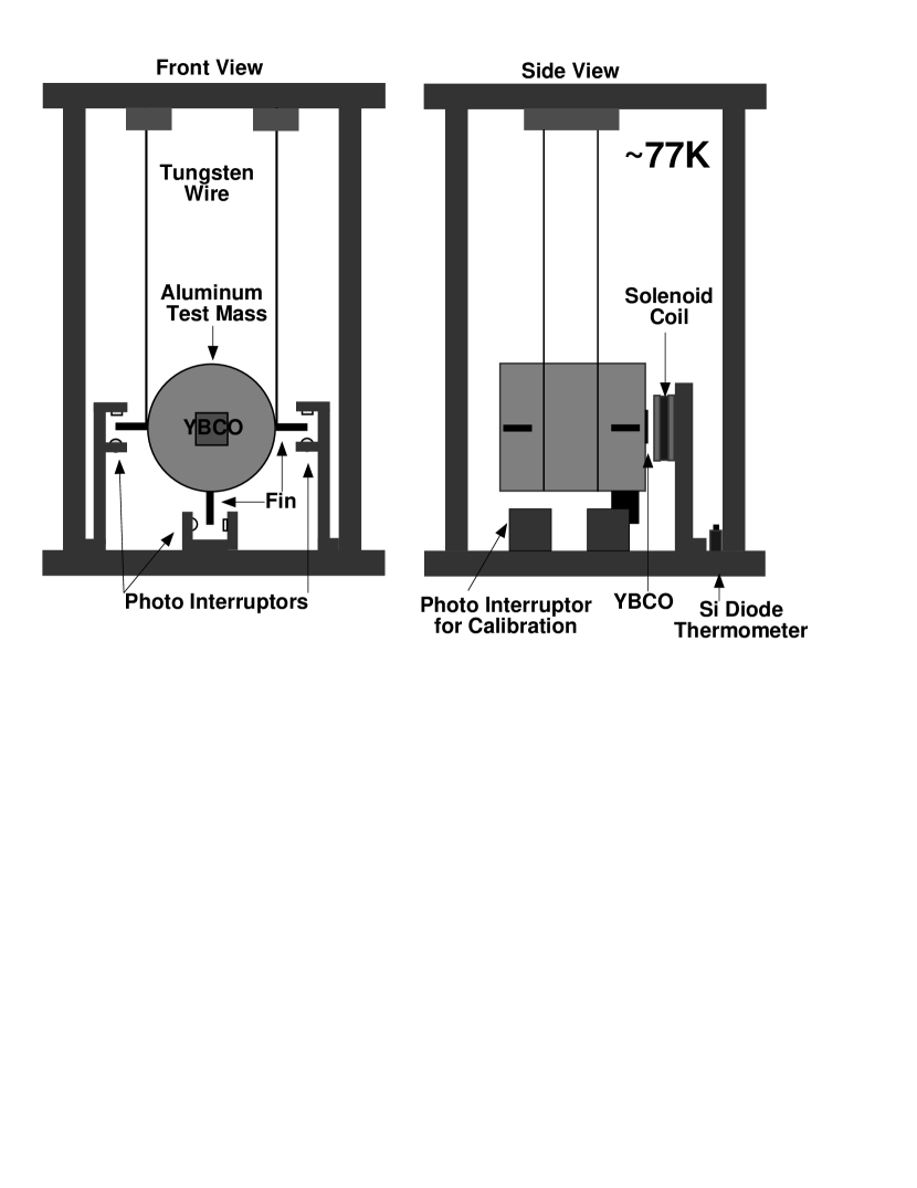
This setup simulated a part of a pendulum of the Fabry-Perot cavity of an interferometric gravitational-wave detector. A cylindrical aluminum test mass had dimensions of 5 cm in diameter and 6 cm in length. It was suspended by two tungsten wires. The length of the pendulum was about 20 cm. Superconducting film of 0.9 cm0.9 cm area was glued to one end of the center of the test mass by epoxy glue (Stycast2850FT). The film was a single-sided deposition of superconducting material on a substrate, and the side glued was the deposited one.
A solenoid coil wound with a wire of 0.4 mm in diameter was 2.2 cm in inner diameter, 4.4 cm in outer diameter, and 1 cm in length.
On the barrel of the test mass, five rectangular fins were attached, four of which were for monitoring the position and alignment in relation to the solenoid coil, and one of which was for measuring the displacement of the test mass along the direction of the force.
A fin was set between an infrared LED and an InGaAs photodiode with an effective area diameter of 1 mm. They made a photo-interruptor. The fin interrupted a part of light emitted by the LED according to the motion of the test mass, and the photodiode detected light whose intensity was proportional to the displacement of the fin. Another LED-photodiode system was attached to the bottom plate. It was used for calibrating the temperature dependence of the light intensity of the LED. This photo-interruptor monitored the light intensity corresponding to that when a fin was completely outside the detection area of the photodiode.
The pendulum, position sensors, and solenoid coil were installed on a copper frame in a vacuum chamber and cooled to liquid-nitrogen temperature in a cryostat.
A constant current of 30 mA was provided to the LEDs by constant-current drivers. The output currents of photodiodes were converted to voltages by operational amplifiers. They were fed to low-pass filters of 0.1 Hz cutoff frequency to extract the DC component of from the time varying displacement of the test mass. This DC component output was read with a digital multimeter. All of the converted voltages of the photodiodes’ outputs were monitored with a chart recorder.
2.4 Estimation of from the photodiode output
The relation between the output of a photodiode in a photo-interruptor and the position of a fin was measured in air at room temperature without a coil current, and was fitted as a linear function. The slope () of a fitted straight line depended on the photo-interruptor. For five photo-interruptors the slopes ranged from 0.52 /mV to 0.65 /mV. The fitted range of the position was 400 , in which linearity was confirmed by a simple geometrical calculation. Even if the fitting range had been changed, the difference in the slope would have been a few %.
For the coil current () at the cryogenic temperature (), the output voltage () from a photodiode was converted to the corresponding output at room temperature, assuming that (1) the temperature was the same for all photo-interruptors, and (2) the temperature dependence of the photo-interruptor output was the same. Thus, with the output of the calibration photo-interruptor at the cryogenic temperature and at room temperature, the displacement of the test mass was estimated as follows:
| (3) |
In Eq.(3), was not always 77 K, but depended on the coil current.
2.5 Selection of a superconducting film
The temperature of sapphire substrates for the LCGT mirrors cannot be decreased below 20 K when they are linked thermally to liquid-helium temperature through a heat link system and a sapphire fiber suspension, since the heat, which is generated by partial absorption of the laser beam in the substrates, transfers through only conduction of the fibers [4, 3]. Then, the critical temperature of the superconducting film is required to be greater than 20 K, because it is attached to the substrate. Thus, we selected a commercially available high-temperature superconducting thin film of YBCO. The YBCO film which we used for the experiment was deposited by the reactive thermal co-evaporation technique on a MgO substrate, and was 1.6 thick, 0.9 cm0.9 cm in area, 88.6 K in critical temperature, and 2.7 MA/cm2 in critical current density [8].
3 Results
Figure 3 shows the dependence of the displacement of a test mass on the current flowing in the solenoid coil.
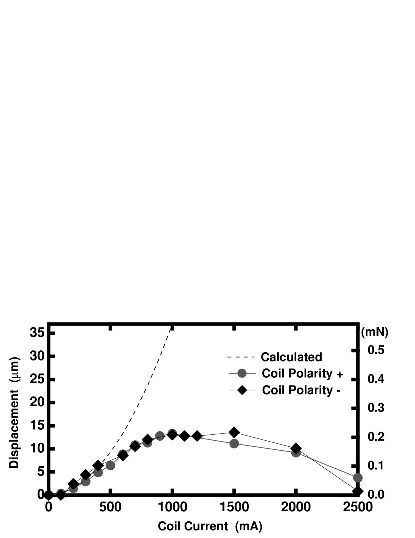
At the position of the YBCO film the magnetic field was about 3.5 mT for a 500 mA coil current. Using Eq.(2), the force applied by the actuator was obtained from the displacement of the test mass multiplied by 16 N/m.
After the cryogenic actuator was cooled down to 77 K without a magnetic field, the coil current was raised from 0 to the setting value. The steps of the measuring procedure were (1) setting the coil current, (2) measuring the displacement of the test mass after the oscillation amplitude of the test mass was reduced sufficiently, (3) decreasing the coil current to zero, and (4) continuing the same procedure for the next coil current.
When the polarity of the coil current was changed, the direction of the force by the actuator to the test mass was not changed. Also, the values of the forces were almost the same for both polarities.
The force by the actuator exceeded 0.1 mN for a coil current of 600 mA and had a maximum value of about 0.2 mN for 1 A. For coil currents below 400 mA, the measured forces were consistent with the estimated values for the ideal superconducting film by Eq.(1). The discrepancies for currents above 400 mA might not be due to a decrease of the vortex-free region because, even for a 2A coil current, the applied magnetic field was about half of the characteristic critical field [9, 10], which saturated the magnetic moment of the film with its critical current density; moreover, another study showed a larger force [11]. We guess that they came from a tiny break of the YBCO film by a mismatch of the thermal expansion between the YBCO film and the epoxy glue.
4 Discussions
4.1 Requirement for LCGT
LCGT may have sapphire substrates for mirrors with a mass of 54 kg and 1 m long pendulums; thus, to displace the mirror up to 1 m for fringe lock, the actuator for LCGT must apply a force larger than 0.5 mN. With a safety factor, a force of 2 mN by the actuator is needed.
4.2 Superconducting film for LCGT
Unlike conventional actuators with permanent magnets and coils, the direction of force applied by the superconducting film actuator to the mirror is only repulsive for a weak applied magnetic field. If we need an attractive force for fringe lock, we have two examples of options.
One of them is to attach superconducting films to both ends of the cylindrical substrate of the mirror. A force in the opposite direction can be applied by the films on the opposite end. The experimental results presented show that the actuator with four YBCO films of 1.5 cm1.5 cm attached to both ends of the cylindrical substrate of the mirror for LCGT could displace the mirror sufficiently in both directions.
Another method is to shift the equilibrium position of the pendulum by adding a bias current to the coil and to keep the position of the mirror whose horizontal component of gravitational force is always opposite to the repulsive force by the actuator. In this method the superconducting films may be attached to one end of the cylindrical substrate. If YBCO films of the same total area as that of the first example are attached to one side of the substrate of the LCGT mirror, they would similarly work as the first example.
Although the cryogenic actuator which we studied consisted of a thin film, epoxy glue and the YBCO film, itself, would induce extra thermal noise. As for a YBCO film, the critical limit of film thickness deposited on the sapphire substrate with a CeO2 buffer layer is 300 nm due to a mismatch of the thermal expansion between the substrate and the YBCO film [8]. Thus, we need to further examine whether the value does not decrease with the YBCO film glued on the test mass and to measure the reduction of force with a YBCO film of 300 nm thick.
5 Conclusions
We measured the forces applied by a cryogenic actuator with a YBCO film of 1.6 m in thickness and 0.81 cm2 in area driven by a solenoid coil at 77 K. The force was applied up to 0.2 mN. This measurement shows that a YBCO film actuator can be used for fringe lock of the LCGT interferometer from the viewpoint of force.
References
- [1] A.D. Gillespie, Thermal Noise in the Initial LIGO Interferometers. PhD Thesis, California Institute of Technology, 1995.
- [2] K. Yamamoto, Study of the thermal noise caused by inhomogeneously distributed loss. PhD Thesis, University of Tokyo, 2000.
- [3] K. Kuroda et al., Int. J. Mod. Phys. D5 (1999) 557.
- [4] T. Uchiyama et al., Phys. Lett. A242 (1998) 211.
- [5] T. Uchiyama et al., Phys. Lett. A261 (1999) 5.
- [6] T. Uchiyama et al., Phys. Lett. A273 (2000) 310.
- [7] L.D. Landau, E.M. Lifshitz, and L.P. Pitaevskii, Course in Theoretical Physics Vol.8: Electrodynamics of Continuous Media, Butterworth-Heinemann, Oxford, 1984.
- [8] THEVA DÜNNSCHICHTTECHNIK GMBH, Technical Product Information, 1999.
- [9] P.N. Mikheenko and Yu.E. Kuzovlev, Physica C204 (1993) 229.
- [10] J.R. Clem and A. Sanchez, Phys. Rev. B50 (1994) 9355.
- [11] B.R. Weinberger, Applied Superconductivity 2 (1994) 511.