Uplink Capacity and Interference Avoidance for Two-Tier Femtocell Networks
Abstract
Two-tier femtocell networks– comprising a conventional cellular network plus embedded femtocell hotspots– offer an economically viable solution to achieving high cellular user capacity and improved coverage. With universal frequency reuse and DS-CDMA transmission however, the ensuing cross-tier interference causes unacceptable outage probability. This paper develops an uplink capacity analysis and interference avoidance strategy in such a two-tier CDMA network. We evaluate a network-wide area spectral efficiency metric called the operating contour (OC) defined as the feasible combinations of the average number of active macrocell users and femtocell base stations (BS) per cell-site that satisfy a target outage constraint. The capacity analysis provides an accurate characterization of the uplink outage probability, accounting for power control, path loss and shadowing effects. Considering worst case interference at a corner femtocell, results reveal that interference avoidance through a time-hopped CDMA physical layer and sectorized antennas allows about a 7x higher femtocell density, relative to a split spectrum two-tier network with omnidirectional femtocell antennas. A femtocell exclusion region and a tier selection based handoff policy offers modest improvements in the OCs. These results provide guidelines for the design of robust shared spectrum two-tier networks.
Index Terms:
Operating Contours, Code Division Multiaccess, Macrocell, Femtocell, Cellular, Uplink Capacity, Outage ProbabilityI Introduction
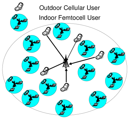
Two-tier femtocell networks (Fig. 1) are in the process of being deployed to improve cellular capacity [1, 2]. A femtocell serves as a small range data access point situated around high user density hot-spots serving stationary or low-mobility users. Examples of femtocells include residential areas with home LAN access points, which are deployed by end users and urban hot-spot data access points. A femtocell is modeled as consisting of a randomly distributed population of actively transmitting users. The femtocell radio range ( meters) is much smaller than the macrocell radius ( meters) [3]. Users transmitting to femtocells experience superior signal reception and lower their transmit power, consequently prolonging battery life. The implication is that femtocell users cause less interference to neighboring femtocells and other macrocell users. Additionally, a two-tier network offsets the burden on the macrocell BS, provided femtocells are judiciously placed in traffic hot-spots, improving network capacity and QoS.
Because of the scarce availability of spectrum and for reasons of flexible deployment, it may be easier for cellular operators to implement a two-tier network by sharing spectrum, rather than splitting spectrum between tiers. The focus of this work is to answer the following questions:
-
•
What is the two-tier uplink capacity in a typical macrocell with randomly scattered hotspots, assuming a randomly distributed population of actively transmitting users per femtocell?
-
•
Is it possible to accurately characterize the statistics of the cross-tier interference? What is the effect of the femtocell hotspot density, macrocell-femtocell power ratio and femtocell size?
-
•
How much benefit is accrued by interference avoidance using antenna sectoring and time hopping in CDMA transmission? What is the impact of using a femtocell exclusion region and a tier selection policy for femtocell handoff?
By addressing these questions, our work augments existing research on capacity analysis and interference mitigation in two-tier networks. We show that creating a suitable infrastructure for curbing cross-tier interference can actually increase the uplink capacity for a shared spectrum network.
I-A Related work
From a physical layer viewpoint, prior research has mainly focused on analyzing the uplink capacity, assuming either a single microcell111In the context of this paper, a microcell has a much larger radio range (100-500 m) than a femtocell. or multiple regularly spaced microcells in a macrocell site. This model has assumed significance for its analytical tractability, nonetheless, it has limited applicability owing to the inherent variability in microcell locations in realistic scenarios.
The ideas presented in this paper are most closely related to the work by Kishore et al. The downlink cellular capacity of a two-tier network is derived in [4]. The results show that the cellular user capacity is limited by uplink performance for both slow and fast power control. In [5], the OCs for a two-tier network are derived for different tier-selection schemes, assuming an arbitrarily placed microcell. Further work by the same author [6, 7] extended the framework to multiple microcells embedded inside multiple macrocells. The cross-tier interference is approximated by its average and cross-tier microcell to microcell interference is ignored. The resulting analysis is shown to be accurate only up to 8 microcells per macrocell. Our results, on the other hand, are accurate over a wide range of femtocell densities, without approximating the interference statistics.
Related work includes [8], which discusses the benefits of having a tilted antenna radiation pattern and macrocell-microcell power ratio control. In [9, 10], a regular network comprising a large hexagonal macrocell and smaller hexagonal microcells is considered. Citing near far effects, the authors conclude that it is more practical to split the RF spectrum between each tier. The reason being that the loss in trunking efficiency by splitting the spectrum is lower than the increase in outage probability in a shared spectrum two-tier network. Our paper, in contrast, shows a higher user capacity for a shared spectrum network by enforcing higher spatial reuse through small femtocells and interference avoidance by way of antenna sectoring and Time hopped CDMA (TH-CDMA) in each tier.
Finally, from a network perspective, Joseph et al. [11] study impact of user behavior, load balancing and different pricing schemes for interoperability between Wi-Fi hotspots and cellular networks. In [3], the design of a multitiered wireless network with Poisson call arrivals is formulated as an constrained optimization problem, and the results highlight the economic benefits of a two-tier network infrastructure: increased stability in system cost and a more gradual performance degradation as users are added.
I-B Contributions
This paper employs a stochastic geometry framework for modeling the random spatial distribution of users/femtocells, in contrast to prior work [5, 7, 6, 12, 9, 10]. Hotspot locations are likely to vary from one cellsite to another, and be opportunistic rather than planned: Therefore a capacity analysis that embraces instead of neglecting randomness will naturally provide more accurate results and more plausible insights.
To model the user/hotspot locations, the paper assumes that the macrocell users and femtocell BS are randomly distributed as a Homogeneous Spatial Poisson Point Process (SPPP) (see [13, 14] for background, prior works include [15, 16, 17]). The three key contributions in our paper are summarized below.
-
•
First, a novel outage probability analysis is presented, accounting for cellular geometry, cross-tier interference and shadowing effects. We derive tight lower bounds on statistics of macrocell interference at any femtocell hotspot BS along the hexagonal axis. Next, assuming small femtocell sizes, a Poisson-Gaussian model for macrocell interference and alpha-stable distribution for cross-tier femtocell interference is shown to accurately capture the statistics at the macrocell BS. In the analysis, outage events are explicitly modeled rather than considering average interference as in [9, 12]. For doing so, the properties of Poisson shot-noise processes (SNP)[18, 19] and Poisson void probabilities [13] are used for deriving the uplink outage probabilities.
-
•
Second, robust interference avoidance is shown to enable two-tier networks with universal frequency reuse to achieve higher user capacity, relative to splitting the spectrum across tiers. With interference avoidance, an equitable distribution of users between tier 1 and tier 2 networks is shown to be achieved with an order-wise difference in the ratio of their received powers. Even considering the worst case cross-tier interference at a corner femtocell, results for moderately loaded cellular networks reveal that interference avoidance provides a x increase in the mean number of femtocells over split spectrum two-tier networks.
-
•
Third, additional interference avoidance using a combination of femtocell exclusion and tier selection based femtocell handoff offers modest improvements in the network OCs. This suggests that at least for small femtocell sizes, time hopping and antenna sectoring offer the largest gains in user capacity for shared spectrum two-tier networks.
II System Model
Denote as the interior of a reference hexagonal macrocell of radius . The tier 1 network consists of low density cellular users that are communicating with the central BS in each cellsite. The cellular users are distributed on according to a homogeneous SPPP of intensity . The overlaid tier 2 network containing the femtocell BS’s forms a homogeneous SPPP222The system model allows a cellular user to be present inside a femtocell as the governing process is homogeneous. with intensity . Each femtocell hotspot includes a Poisson distributed population of actively transmitting users333A hard handoff is assumed to allocate subscribed hotspot users to a femtocell, provided they fall within its radio range. with mean in a circular coverage area of radius . To maximize user capacity per cellsite, it is desirable to have ; as will be shown, cross-tier interference at a macrocell BS limits for a given . Defining as the area of the hexagonal region , the mean number of macrocell users and femtocell BS’s per cellsite are given as and respectively. Table I shows a summary of important parameters and typical values for them, which are used later in numerical simulations.
Users in each tier employ DS-CDMA with processing gain . Uplink power control adjusts for propagation losses and log-normal shadowing, which is standard in contemporary CDMA networks. The macrocell and femtocell receive powers are denoted as and respectively. Any power control errors [20] and short-term fading effects are ignored for analytical convenience. We affirm this assumption as reasonable, especially in a wideband system with significant frequency diversity and robust reception (through RAKE receiver, coding and interleaving).
II-A TH-CDMA and Antenna sectoring
Suppose that the CDMA period is divided into hopping slots, each of duration . Every macrocell user and femtocell (all active users within a femtocell transmit in the same hopping slot) independently choose to transmit over any one slot, and remain silent over the remaining slots. The resulting intra- and cross-tier interference are “thinned” by a factor of [13]. Using TH-CDMA, users in each tier effectively sacrifice a factor of their processing gain, but benefit by thinning the interfering field by the same factor.
We further assume sectorized antenna reception in both the macrocell and femtocell BS, with antenna alignment angle and sector width equaling . While antenna sectoring is a common feature at the macrocell BS in practical cellular systems, this paper proposes to use sectorized antennas at femtocell BS’s as well. The reason is that the cross-tier interference caused by nearby cellular users can lead to unacceptable outage performance over the femtocell uplink; this motivates the need for directed femtocell antennas. The spatial thinning effect of TH-CDMA transmission and antenna sectoring is analytically derived in the following lemma.
Lemma 1 (Spatial thinning by interference avoidance)
With TH-CDMA transmission over slots and antenna sectoring with directed BS antennas in each tier, the interfering field at a given antenna sector can be mapped to the SPPPs and on with intensities and respectively.
Proof:
See Appendix A. ∎
The following definitions will be useful in the remainder of the paper.
Definition 1
Denote as the region within covered by a antenna sector corresponding to a macrocell BS or a femtocell BS within the reference cellsite. For example, for an omnidirectional femtocell located at the corner of the reference macrocell.
Definition 2
Denote and as the heterogeneous SPPPs composed of active macrocell and femtocell interferers as seen at a antenna sector in each tier, whose intensities are given by and in (A). Denote the equivalent mapped homogeneous SPPPs over by and whose intensities are given by and respectively.
Definition 3
Denote the restriction of and to by the SPPPs and respectively.
II-B Channel Model and Interference
The channel is represented as a combination of path loss and log-normal shadowing. The path loss exponents are denoted by (outdoor transmission) and (indoor femtocell transmission) with random lognormal shadowing standard deviation . Through uplink power control, a macrocell user transmitting at a random position w.r.t the reference macrocell BS chooses a transmit power level . Here is the attenuation function for outdoor propagation, defined as where is the log-normal shadowing from user to , is a unitless constant that depends on the wavelength of the RF carrier and outdoor reference distance .
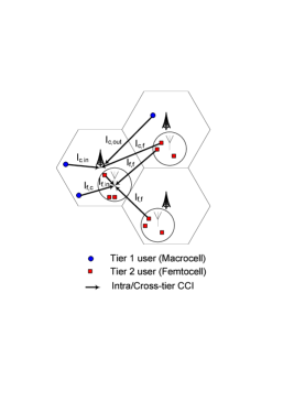
Similarly, a femtocell user at a random position within a femtocell BS chooses a transmit power , where represents the indoor attenuation, and . Here is the reference distance for calculating the indoor propagation loss. Note that in reality, and are empirically determined. The interference in each tier (Fig. 2) can be grouped as:
- Macrocell interference at a macrocell.
-
Through power control, all macrocell users within are received with constant power , so the in-cell interference equals , where . As such, inferring the exact statistics of out-of-cell cellular interference is analytically intractable; it is assumed that is distributed according to a scaled Gaussian pdf [15]. Defining and to be the empirically determined parameters of the Gaussian, the pdf of is given as , where .
- Femtocell interference at a macrocell.
-
Say femtocell with users is located at random position w.r.t the reference macrocell BS . Inside , a randomly placed Tier 2 user at distance from the femtocell BS transmits with power . The interference caused at from user inside is given as,
(1) where . In doing so, we make two important assumptions:
AS 1
For small sized femtocells (), a femtocell or macrocell BS sees interference from other femtocells as a point source of interference, implying .
AS 2
When analyzing the interference caused by a random femtocell at any other location, the femtocell users can be modeled as transmitting with maximum power, so that . This is for analytical tractability and modeling worst-case interference.
Summing (Femtocell interference at a macrocell.) over all femtocells over a antenna sector at a macrocell BS, the cumulative cross-tier interference at the reference macrocell BS is represented by the Poisson SNP [18],
(2) where defines the cumulative shadowing gain between actively transmitting users in femtocell and macrocell BS .
- Neighboring femtocell interference at a femtocell.
-
By an identical argument as above, the interference caused at the BS antenna sector of femtocell from other femtocells is a Poisson SNP given by , where refers to the distance between and .
- Interference from active users within a femtocell.
-
Conditioned on the femtocell containing actively transmitting users (), the intra-tier interference experienced by the user of interest arising from simultaneous transmissions within the femtocell is given as .
- Macrocell interference at a femtocell.
-
This paper analyzes outage probability at a femtocell BS located on the hexagonal axis, considering the effect of in-cell cellular interference. The cumulative tier 1 interference experienced at a femtocell can be lower bounded by the interference caused by the set of tier 1 interferers inside the reference macrocell . This lower bound is represented as , where is the LN shadowing term and represent the distances of macrocell user to the macrocell BS and femtocell BS respectively. Observe that a corner femtocell experiences a significantly higher macrocell interference relative to an interior femtocell, therefore the cdf is not a stationary distribution.
III Per Tier Outage Probability
To derive the OCs, an uplink outage probability constraint is formulated in each tier. Define and as the average number of femtocell BS’s and macrocell users per cellsite respectively. A user experiences outage if the instantaneous received Signal-to-Interference Ratio (SIR) over a transmission is below a threshold . Any feasible satisfies the outage probability requirements in each tier. The outage probabilities [resp. ] are defined as the probabilities that the despread narrowband SIR for a macrocell user [femtocell user] at the tier 1 [tier 2] antenna sector is below . Assuming the PN code cross-correlation equals 444With , the model reduces to a non CDMA narrowband transmission; with , the model reduces to a timeslotted ALOHA transmission, define
| (3) |
where denotes the number of points in and the unconditioned . The OCs for the macrocell [resp. femtocell] are obtained by computing the Pareto optimal pairs which satisfy a target outage constraint . More formally,
| (4) | ||||
| (5) |
The OCs for the two-tier network are obtained corresponding to those feasible combinations of that simultaneously satisfy and respectively. For doing so, we derive the following theorems which quantify the outage probabilities and interference statistics in each tier.
Theorem 1
For small femtocell sizes, the statistics of the cross-tier femtocell interference (and intra-tier femtocell interference ) at a antenna sector are given by a Poisson SNP with iid and . In particular, if the outdoor path loss exponent , then follows a Lévy-stable distribution with stability exponent , whose probability density function (pdf) and cumulative distribution function (cdf) are given as,
| (6) |
where .
Proof:
See Appendix B. ∎
Remark 1 (Femtocell size)
Increasing femtocell size () strictly increases the outage probabilities arising from the femtocell interference and in a two-tier network. To elucidate this, observe that an increase in causes to increase by a factor . By monotonicity of , the cdf’s decrease as increases, causing a higher outage probability per tier. Intuitively, a femtocell user located on the edge of a femtocell will cause excessive interference at a nearby femtocell BS; this edge effect appears as a power control factor in (6).
Remark 2 (Hopping Protocol)
All Tier 2 users within a femtocell are assumed to jointly choose a hopping slot. Suppose we compare this against an independent hopping protocol, where users within a femtocell are independently assigned a hopping slot. With independent hopping, the intensity of equals (note the difference from in Lemma 1) and the average number of interfering users in an actively transmitting femtocell equals . With an outage threshold of (III) at a femtocell BS, two observations are in order:
- TH-CDMA transmission:
-
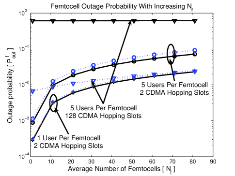
When , joint hopping is preferable from an outage probability perspective. Intuitively, joint hopping reduces by a factor , causing a quadratic decrease in in (6); independent hopping decreases the number of interfering users per active femtocell, causing a sub-quadratic decrease in . The consequence is that joint hopping results in a greater decrease in . Using , Fig. 3 confirms this intuition; notably, the gap in outage performance is dictated by the hotspot user density: In heavily loaded femtocells (), a joint hopping scheme is clearly superior. For lightly loaded femtocells, , implying that independent and joint hopping schemes perform nearly identical.
- Random Access transmission:
-
When , the femtocell outage threshold is ; by consequence, it is preferable to use independent hopping across the tier 2 network (see Fig. 3). With joint hopping, even a single interferer within a femtocell can cause outage for the user of interest as there is no CDMA interference averaging; in contrast, independent hopping offers increased interference avoidance since the likelihood of two femtocell users sharing a hopping slot is negligible. Consequently, in non-CDMA two-tier cellular networks employing interference avoidance, an independent assignment of hopping slots is preferable from an outage viewpoint.
Using Theorem 1, the cellular outage probability is now formulated.
Theorem 2 (Macrocell outage probability)
Let the outdoor path loss exponent . With Poisson in-cell macrocell interference , Gaussian out-of-cell interference and Lévy-stable femtocell interference given by (6), the outage probability at the macrocell BS antenna sector is given as,
| (7) |
where , and
Proof:
See Appendix C. ∎
Theorems 1 and 2 provide the tools to quantify the largest that can be accommodated at a given subject to an outage constraint . The next step is to compute the outage probability at a femtocell as defined in (III). To do so, assume that the femtocell is located on the axis at a distance from the macrocell center and the femtocell antenna sector is aligned at angle w.r.t the hexagonal axis.
The following theorem derives a lower bound on the tail probability for the distribution of the tier 1 interference , experienced at any femtocell located along the hexagonal axis.
Theorem 3 (Lower bound on cellular interference)
At any femtocell antenna sector located at distance from the macrocell BS along the hexagonal axis:
-
1.
The complementary cumulative distribution function (ccdf) of the cellular interference over a femtocell antenna sector is lower bounded as , where:
(8) Here is the ccdf of , , is the femtocell BS antenna alignment angle and denotes the region inside the reference macrocell enclosed between .
-
2.
For a corner femtocell with an omnidirectional femtocell antenna , the ccdf of is lower bounded as , where :
(9)
Proof:
See Appendix D. ∎
For a path loss only model, the lower bounds on the femtocell outage probability can be derived analogously as stated in the following corollary.
Corollary 1
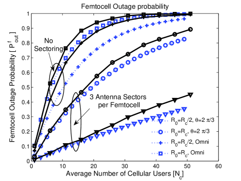
Theorem 3 characterizes the relationship between the intensity of macrocell users and the femtocell outage probability. Observe that the outage probability exponentially, as . Further, increasing “thins” the intensity of , thereby mitigating cross-tier interference at the femtocell BS. Fig. 4 depicts the outage lower bounds to evaluate the impact of cellular interference . Corresponding to an interior and corner femtocell location, the lower bounds are computed when the femtocell BS antenna is either sectorized– with antenna alignment angle – or omnidirectional. No hopping is used (), while a unity power ratio () is maintained. Two observations are in order:
- Tightness of lower bound:
-
The tightness of (8) and (9) shows that the cross-tier interference is primarily impacted by the set of dominant cellular interferers (D). The implication is that one can perform accurate outage analysis at a femtocell by considering only the cellular users whose transmissions are strong enough to individually cause outage. This agrees with the observations in [21, 22].
- Infeasibility of omnidirectional femtocells:
-
The benefits of sectorized antennas for interference mitigation at the femtocell BS are evident; with a sectorized BS antenna, a corner femtocell (worst-case macrocell interference) performs considerably better than an interior omnidirectional femtocell.
Using Theorems 1 and 3, the femtocell outage probability (III) is stated in the next theorem.
Theorem 4 (Femtocell outage probability)
Let outdoor path loss exponent . For small , the femtocell outage probability is lower bounded as:
| (10) |
where , and .
Proof:
See Appendix E. ∎
For a given , Theorem 4 computes the largest which ensures the SIR threshold is satisfies for a fraction () of the time. Furthermore, the lower bound was shown to be tight, hence the computed is not overly optimistic. Using Theorems 2 and 4, the OCs for the two-tier network with interference avoidance can now be readily obtained. The following section studies using a femtocell exclusion region around the macrocell BS and a tier selection based femtocell handoff policy, in addition to the interference avoidance strategies discussed hitherto.
IV Femtocell exclusion region and Tier Selection
Suppose the reference macrocell BS has a femtocell exclusion region surrounding it. This idea is motivated by the need to silence neighboring femtocell transmissions which are strong enough to individually cause outage at a macrocell BS; similar schemes have been proposed in [23] and adopted in the CSMA scheduler in the 802.11 standard. The tier 2 femtocell network then forms a heterogeneous SPPP on with the average number of femtocells in each cell-site equaling . The following theorem derives a lower bound on the ccdf of the cross-tier femtocell interference considering the effect of a femtocell exclusion region.
Lemma 2 (Femtocell exclusion region)
With a femtocell exclusion region of radius around the reference macrocell BS, the ccdf of cross-tier femtocell interference is lower bounded as:
| (11) |
where is defined as,
| (12) |
Proof:
See Appendix F. ∎
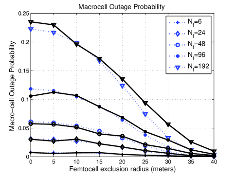
Fig. 5 depicts the macrocell outage performance as a function of the femtocell exclusion radius, assuming . Notice that even a small exclusion radius results in a significant decrease in . The implication is that a femtocell exclusion region can increase the number of simultaneous active femtocell transmissions, while satisfying the macrocell outage constraint . Once again, the close agreement between analysis and simulation shows that only the nearby dominant femtocell interferers influence outage events at the macrocell BS.
Corollary 2
With no femtocell exclusion (), the ccdf of the cross-tier femtocell interference at a macrocell is lower bounded as .
Corollary 2 is the two-tier cellular network equivalent of Theorem 3 in Weber et al. [22], which derives a lower bound on the outage probability for ad hoc networks with randomized transmission and power control. Finally, this paper considers the influence of a femtocell tier selection based handoff policy wherein any tier 1 cellular user within the radius of a femtocell BS undergoes handoff to the femtocell. In essence, the interference caused by the nearest macrocell users is mitigated, as these users now employ power control to the femtocell BS.
Lemma 3
With a tier selection policy in which any user within a radius of a femtocell undergoes handoff to the femtocell BS, the intensity of tier 1 users within after handoff is given as whenever , where is the femtocell exclusion radius.
Proof:
See Appendix G. ∎
Remark 3
For small and , a first-order Taylor approximation shows that . The interpretation is that tier-selection offers marginal benefits for small femtocell sizes (). Intuitively, a small sized femtocell does not cover “enough space” for significant numbers of cellular users in to accomplish femtocell handoff. However, Theorem 1 shows that a small femtocell size does lead to a lower uplink outage probability.
V Numerical Results
System parameters are given in Table I. The setup consists of the region surrounded by macrocell sites to consider two rings of interferers and sectorized antennas at each BS. In (11), the statistics of the shadowing gain were empirically estimated using the MATLAB functions ksdensity and ecdf respectively. The OCs were analytically obtained using Theorems 1-4 for an outage constraint in (LABEL:eq:Twotier_OC). The following plots compare the OCs for a shared spectrum network with interference avoidance against a split spectrum network with omnidirectional femtocells.
| Symbol | Description | Value |
|---|---|---|
| Region inside reference cellsite | N/A | |
| SPPPs defining Tier 1, Tier 2 users | N/A | |
| Macrocell, Femtocell Radius | meters | |
| Poisson mean users per femtocell | 5 | |
| Antenna sectors | 3 | |
| CDMA Hopping slots | ||
| Processing Gain | ||
| Target SIR per tier | [C/I= dB] | |
| Target Outage Probability | 0.1 | |
| Macrocell receive power | 1 | |
| Femtocell receive power | 1,10,100 | |
| Lognormal shadowing parameter | dB | |
| Path loss exponents | ||
| Reference distances | meters | |
| Carrier Frequency | GHz |
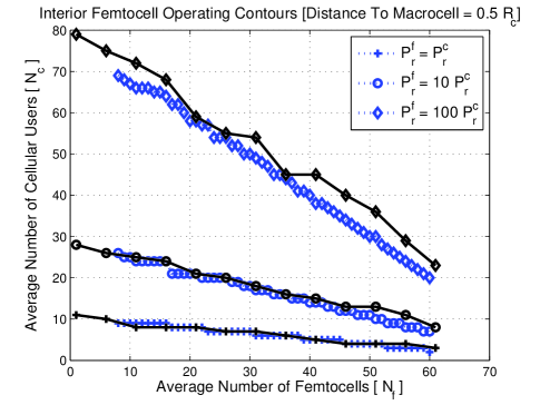
Figs. 6 and 7 plot OCs for a macrocell and interior femtocell with and . The femtocell uses a sectorized receive antenna with . The close agreement between the theoretical and empirical OC curves indicates the accuracy of the analysis. Observe that the outage constraints oppose one another: Relative to the macrocell, increasing decreases the largest sustainable for a given . From the femtocell standpoint, increasing increases the largest sustainable for a given .
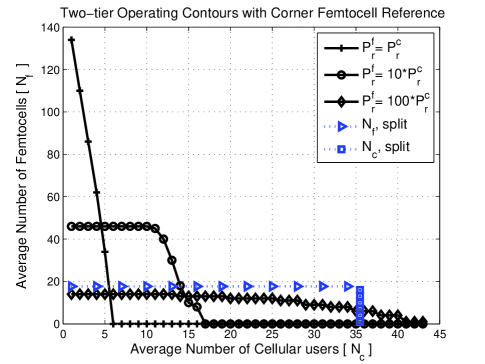
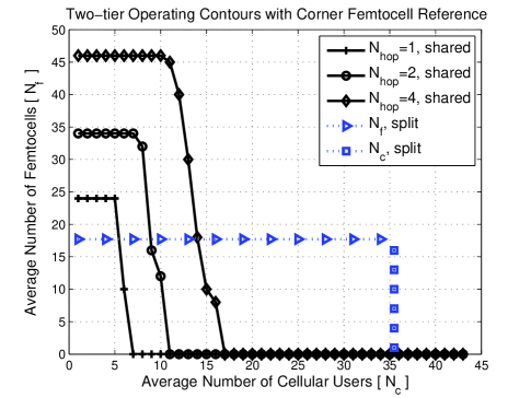
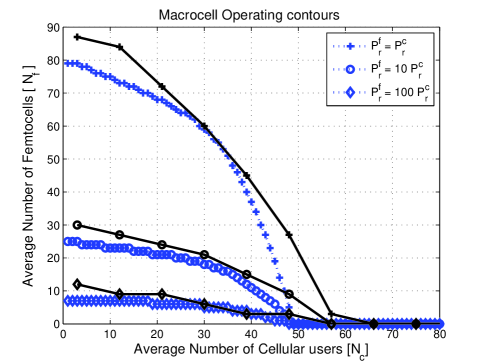
Figs. 8 through 10 plot the performance of the shared spectrum network employing interference avoidance for a corner and an interior femtocell, as a function of and . Fig. 8 shows that with and a lightly loaded tier 1 network, the corner femtocell can achieve a nearly x improvement in relative to the split spectrum network. Intuitively, with , a macrocell BS tolerates a large cross-tier interference; the downside being that the femtocell BS experiences higher cellular interference arising from tier 1 users transmitting at maximum power near the cell edge. This explains why decreases rapidly with increasing in the OC curves for a corner femtocell. This also suggests that achieving load balancing by increasing at the expense of requires an order wise difference in the femtocell-macrocell receive power ratio. We suggest that a practical wireless system use a larger femtocell-macrocell receive power ratio () at the corner femtocell, relative to an interior femtocell. Such a position based variable power ratio would ensure that both the interior and corner femtocells can tolerate interference from an almost identical number of tier 1 users.
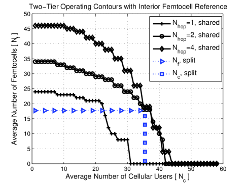
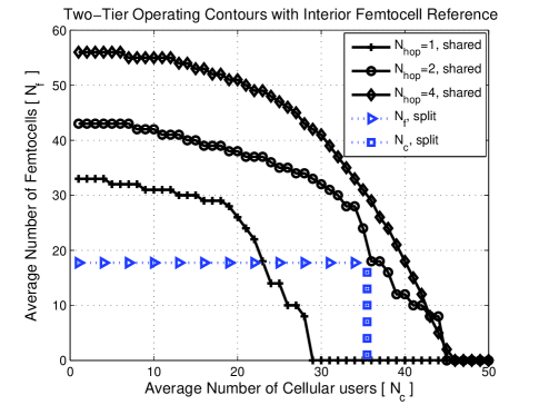
With and slots, the OCs for corner and interior femtocells in Figs. 9 and 10 offer greater than x improvement in relative to the split spectrum network. Additionally, a greater degree of load balancing is achieved: with an interior femtocell location, a maximum of tier 1 users can be accommodated.
Fig. 11 shows the two-tier OCs when users in each tier employ a femtocell exclusion region and a tier selection policy for femtocell handoff. We observe an increase in by up to additional femtocells (or users) for users. Both femtocell exclusion and tier selection do not result in a higher . The reason is that a femtocell exclusion region does not alleviate tier 1 interference at a femtocell. Furthermore, an explanation for the conservative gains in is that there is a maximum tolerable interference to sustain the outage requirements at a given femtocell, that prevents a substantial increase in the number of actively transmitting femtocells. Next, owing to small femtocell sizes, a tier selection policy succeeds in curbing tier 1 interference mainly for a large , which is sustainable when is small (to satisfy ). This explains the dominant gains in at a low-to-moderate .
A relevant question is to ask: “How does the system capacity with randomly placed users and hotspots compare against a two-tier network with a given configuration?” Due to space limitations, our paper does not address this question directly. We refer the reader to Kishore et al. [6, Page 1339]. Their results show diminishing gains in the system capacity in absence of interference avoidance, because the configuration contains high levels of cross-tier interference.
Kishore proposes to alleviate cross-tier interference by varying the macrocell coverage region, through exchanging the pilot channel strength with the microcell. Our model assumes that femtocells (placed by end consumer) operate with minimal information exchange with the macrocell BS. Due to reasons of security and scalability–there may be hundreds of embedded femtocells within a densely populated macrocell– handing off unsubscribed users from macrocell to a femtocell hotspot may not be practical. Moreover, femtocell hotspots have a small radio range ( meters). This necessitates an interference avoidance strategy.
VI Conclusion
This paper has presented an uplink capacity analysis and interference avoidance strategy for a shared spectrum two-tier DS-CDMA network. We derive exact outage probability at a macrocell and tight lower bounds on the femtocell outage probability. Interference avoidance through a TH-CDMA physical layer coupled with sectorized receive antennas is shown to consistently outperform a split spectrum two-tier network with omnidirectional femtocell antennas. Considering the worst-case interference at a corner femtocell, the network OCs show a 7x improvement in femtocell density. Load balancing users in each tier is achievable through a orderwise difference in receive powers in each tier. Additional interference avoidance using a femtocell exclusion region and a tier selection based femtocell handoff offers conservative improvements in the OCs. The message is clear: Interference avoidance strategies can make shared spectrum two-tier networks a viable proposition in practical wireless systems.
Acknowledgement
We acknowledge Dr. Alan Gatherer and Dr. Zukang Shen of Texas Instruments for their valuable input and sponsorship of this research. The contributions of Andrew Hunter are also gratefully acknowledged.
Appendix A
Consider the Poisson field of interferers as seen at any antenna sector (either macrocell or femtocell BS) with antenna alignment angle . Assuming a perfect antenna radiation pattern, the interfering Poisson field forms heterogeneous SPPPs and with intensities given by,
| (13) |
where represents the indicator function. The following observations rigorously explain (A).
- Hopping slot selection:
-
The set of macrocell users and femtocell BSs transmitting over any hopping slot is obtained by independent Bernoulli thinning of the SPPPs by the probability of choosing that hopping slot namely .
- Active femtocell selection:
-
The factor arises because the set of femtocells with at least one actively transmitting user is obtained using independent Bernoulli thinning of [13]. Observe that a femtocell with actively transmitting users satisfies .
The event consisting of marking femtocells by the probability that they contain at least one actively transmitting user and the event of marking femtocells by the probability of choosing a common hopping slot are independent; this implies that the resulting SPPP has intensity . Finally, using the Mapping theorem [13, Section 2.3] for Poisson processes, one can map the heterogeneous SPPPs and over one antenna sector to homogeneous SPPPs and over with intensities and respectively.
Appendix B
From (2), (and ) are distributed as a Poisson SNP over an antenna sector of width . Next, the Mapping theorem [13] is used to prove (6).
-
1.
Invoke Lemma 1 for mapping to a homogeneous SPPP on . This implies that is distributed identically as .
-
2.
Map the planar SPPP defining with intensity to a 1D SPPP with intensity using Proposition 1, Theorem 2 in [19]. For doing so, rewrite as, which represents a SPPP on the line with Poisson arrival times and intensity .
Consequently, is identically distributed as a 1D SPPP with intensity , which represents a Lévy-stable distribution with stability exponent [24], and a characteristic function given by , where is the gamma function. In particular, when , follows a Lévy-stable distribution with stability exponent , with statistics (6) obtained from Equation (30) in [18].
Appendix C
At the macrocell BS, the interference denoted by and are mutually independent random variables. The macrocell outage probability defined in (III) can be computed by the probability of the complementary event, corresponding to the probability that the cumulative interference does not exceed the SIR threshold . The cdf of can be computed using a three-fold convolution. Observe that the event that the intra-tier macrocell interference from in-cell tier 1 interferers equals , given at least one active tier 1 user (user of interest), is equivalent to the event that has exactly elements within . The probability of this event is given as,
| (14) |
The total interference caused by the interfering macrocell users equals . Outage does not occur if the residual interference is less than . Using Theorem 1 and independence of the Gaussian distributed and , the result follows.
Appendix D
The interference experienced at a femtocell antenna sector is lower bounded by the cellular interference arising within . If the femtocell BS is located at distance from the reference macrocell, then any macrocell user located at polar coordinates w.r.t the femtocell BS causes an interference equaling at the femtocell BS. Corresponding to the heterogeneous SPPP (see Def. 3), outage events at the femtocell BS arising from cellular interference can be categorized into two types: In the first type, outage events arise due to interference caused by a single user in . The second class of outage events occur due to the macrocell interferers whose cumulative interference causes outage [21]. This class precludes all interferers falling in the first category. Mathematically, for an outage threshold at the femtocell BS, split into two disjoint heterogeneous Poisson SPPPs corresponding to the set of dominant and non-dominant cellular interferers:
| (15) |
At any point , the intensity of denoted by is given as,
| (16) |
In the event of being non empty, the femtocell BS experiences outage, arising from the interference caused by a user in . Therefore, is lower bounded by the probability that has at least one element. Equation (8) results from the Poisson void probability of the complementary event [13]. This completes the proof for the first assertion.
To prove (9), recognize that a corner femtocell with an omnidirectional BS antenna encounters cellular interference from the three surrounding cellsites. The dominant macrocell interferer set can be expressed as , where denotes the dominant macrocell interferer set in neighboring cellsite . The heterogeneous SPPPs are non-intersecting with an intensity expressed by (16). The ccdf of is then lower bounded by the probability of being non empty, which can be deduced from the event that are empty.
| (17) |
To complete the proof, use pairwise independence of the events that and are empty and in (8) to show that is lower bounded as in (D).
Appendix E
The number of femtocell users within a femtocell antenna sector is Poisson distributed with mean . The overall interference is composed of three terms namely and which are mutually independent. Given actively transmitting femtocell users including the user of interest, the interference from users within the femtocell equals . The threshold for to cause outage therefore equals using (III). A lower bound on is obtained as,
| (18) | ||||
Equation (18) uses the lower bound on macrocell interference arising from the set of dominant macrocell interferers (D). Step (a) uses pairwise independence of and for performing a convolution of the respective probabilities. Finally, Step (b) follows from a first-order Taylor series approximation of in (8) using for small in the low outage regime.
Appendix F
Outside the femtocell exclusion region , corresponding to an outage threshold , the SPPP (see Def.2) of intensity can be split into the dominant and non-dominant interfering femtocells denoted by respectively. The heterogeneous SPPP consists of actively transmitting femtocells over which are capable of individually causing outage at a macrocell BS. At any w.r.t macrocell BS, the intensity of equals . The ccdf of the femtocell interference is lower bounded by the probability that is non-empty. For if contains at least one element, then the macrocell antenna sector is in outage (by construction of ). Using the void probability of , the lower bound is given as,
| (19) | ||||
Step (a) in (19) follows by substituting and in (19), while Step (b) is obtained using integration by parts and setting . Using in Step (b) completes the proof.
Appendix G
In the region around the reference macrocell, actively transmitting femtocells are absent, so that there are no femtocells for handoff to occur for any user in . Consequently, the intensity of the tier 1 cellular users in equals . For , the intensity of the macrocell users is found by computing the probability that any point in (prior tier selection) does not fall within meters of a femtocell BS. This is equivalent to computing the void probability of within a circle of radius of every point in , which equals .
This paper assumes an independent Bernoulli thinning of each point in by the probability that a tier 1 user falls with of a femtocell. Strictly speaking, this statement is not correct: Given two closely spaced tier 1 users in , the event that the first user undergoes femtocell handoff is correlated with a nearby user in undergoing handoff with the same femtocell. However, we justify that this assumption is reasonable while considering the small size of each femtocell. Then, the intensity of tier 1 users following the femtocell handoff is obtained by independent Bernoulli thinning of by the void probability [13], which completes the proof.
References
- [1] J. Shapira, “Microcell engineering in CDMA cellular networks,” IEEE Transactions on Vehicular Technology, vol. 43, no. 4, pp. 817–825, Nov. 1994.
- [2] A. Doufexi, E. Tameh, A. Nix, S. Armour, and A. Molina, “Hotspot wireless LANs to enhance the performance of 3G and beyond cellular networks,” IEEE Communications Magazine, vol. 41, no. 7, pp. 58–65, July 2003.
- [3] A. Ganz, C. M. Krishna, D. Tang, and Z. J. Haas, “On optimal design of multitier wireless cellular systems,” IEEE Communications Magazine, vol. 35, no. 2, pp. 88–93, Feb. 1997.
- [4] S. Kishore, L. J. Greenstein, H. V. Poor, and S. C. Schwartz, “Downlink user capacity in a CDMA macrocell with a hotspot microcell,” in Proc., IEEE Global Telecommunications Conference, vol. 3, Dec. 2003, pp. 1573–1577.
- [5] S. Kishore, L. Greenstein, H. Poor, and S. Schwartz, “Uplink user capacity in a CDMA macrocell with a hotspot microcell: Exact and approximate analyses,” IEEE Transactions on Wireless Communications, vol. 2, no. 2, pp. 364–374, Mar. 2003.
- [6] ——, “Uplink user capacity in a multicell CDMA system with hotspot microcells,” IEEE Transactions on Wireless Communications, vol. 5, no. 6, pp. 1333–1342, June 2006.
- [7] S. Kishore, L. J. Greenstein, H. V. Poor, and S. C. Schwartz, “Uplink user capacity in a CDMA system with hotspot microcells: effects of Finite Transmit power and Dispersion,” IEEE Transactions on Wireless Communications, vol. 5, no. 2, pp. 417–426, Feb. 2006.
- [8] D. H. Kim, D. D. Lee, H. J. Kim, and K. C. Whang, “Capacity analysis of macro/microcellular CDMA with power ratio control and tilted antenna,” IEEE Transactions on Vehicular Technology, vol. 49, no. 1, pp. 34–42, Jan. 2000.
- [9] J.-S. Wu, J.-K. Chung, and M.-T. Sze, “Analysis of uplink and downlink capacities for two-tier cellular system,” IEE Proceedings- Communications, vol. 144, no. 6, pp. 405–411, Dec. 1997.
- [10] R. S. Karlsson, “Radio resource sharing and capacity of some multiple access methods in hierarchical cell structures,” in Proc., IEEE Vehicular Technology Conference, vol. 5, Amsterdam, Sept. 1999, pp. 2825–2829.
- [11] D. Joseph, B. Manoj, and C. Siva Ram Murthy, “The interoperability of Wi-Fi hotspots and packet cellular networks and the impact of user behaviour,” in Proc., IEEE International Symposium on Personal, Indoor and Mobile Radio Communications, vol. 1, Sept. 2004, pp. 88–92.
- [12] C.-L. I, L. J. Greenstein, and R. D. Gitlin, “A microcell/macrocell cellular architecture for low- and high-mobility wireless users,” IEEE Journal on Selected Areas in Communications, vol. 11, no. 6, pp. 885–891, Aug. 1993.
- [13] J. Kingman, Poisson Processes. Oxford University Press, 1993.
- [14] M. Haenggi, J. G. Andrews, F. Baccelli, O. Dousse, and M. Franceschetti, “Stochastic geometry and random graphs for the analysis and design of wireless networks,” Submitted, IEEE Journal on Sel. Areas on Comm., 2009, [Online] Available at http://www.nd.edu/ mhaenggi/pubs/.
- [15] C. C. Chan and S. Hanly, “Calculating the outage probability in a CDMA network with Spatial Poisson traffic,” IEEE Transactions on Vehicular Technology, vol. 50, no. 1, pp. 183–204, Jan. 2001.
- [16] F. Baccelli, B. Blaszczyszyn, and F. Tournois, “Spatial averages of coverage characteristics in large CDMA networks,” Wireless Networks, vol. 8, no. 6, pp. 569–586, Nov. 2002.
- [17] S. G. Foss and S. A. Zuyev, “On a Voronoi aggregative process related to a bivariate Poisson process,” Advances in Applied Probability, vol. 28, no. 4, pp. 965–981, Dec. 1996.
- [18] S. Lowen and M. Teich, “Power-law shot noise,” IEEE Transactions on Information Theory, vol. 36, no. 6, pp. 1302–1318, Nov. 1990.
- [19] J. Ilow and D. Hatzinakos, “Analytic alpha-stable noise modeling in a Poisson field of interferers or scatterers,” IEEE Transactions on Signal Processing, vol. 46, no. 6, pp. 1601–1611, June 1998.
- [20] M. G. Jansen and R. Prasad, “Capacity, throughput, and delay analysis of a cellular DS CDMA system with imperfect power control and imperfect sectorization,” IEEE Transactions on Vehicular Technology, vol. 44, pp. 67–75, Feb. 1995.
- [21] S. Weber, X. Yang, J. Andrews, and G. de Veciana, “Transmission capacity of wireless ad hoc networks with outage constraints,” IEEE Transactions on Information Theory, vol. 51, no. 12, pp. 4091–4102, Dec. 2005.
- [22] S. Weber, J. Andrews, and N. Jindal, “The effect of fading, channel inversion, and threshold scheduling on ad hoc networks,” IEEE Transactions on Information Theory, vol. 53, no. 11, pp. 4127–4149, Nov. 2007.
- [23] A. Hasan and J. G. Andrews, “The guard zone in wireless ad hoc networks,” IEEE Transactions on Wireless Communications, vol. 6, no. 3, pp. 897–906, Mar. 2007.
- [24] G. Samorodnitsky and S. Taqqu, Stable Non-Gaussian Random Processes. Chapman and Hall, 1994.