The Case for Redundant Arrays of Internet Links (RAIL)
Abstract
It is well-known that wide-area networks face today several performance and reliability problems. In this work, we propose to solve these problems by connecting two or more local-area networks together via a Redundant Array of Internet Links (or RAIL) and by proactively replicating each packet over these links. In that sense, RAIL is for networks what RAID (Redundant Array of Inexpensive Disks) was for disks. In this paper, we describe the RAIL approach, present our prototype (called the RAILedge), and evaluate its performance. First, we demonstrate that using multiple Internet links significantly improves the end-to-end performance in terms of network-level as well as application-level metrics for Voice-over-IP and TCP. Second, we show that a delay padding mechanism is needed to complement RAIL when there is significant delay disparity between the paths. Third, we show that two paths provide most of the benefit, if carefully managed. Finally, we discuss a RAIL-network architecture, where RAILedges make use of path redundancy, route control and application-specific mechanisms, to improve WAN performance.
1 Introduction
The Internet gradually becomes the unified network infrastructure for all our communication and business needs. Large enterprises, in particular, rely increasingly on Internet-based Virtual Private Networks (VPNs) that typically interconnect several, possibly remote, sites via a wide-area network (WAN). Depending on the company, the VPNs may have various uses, including carrying Voice-over-IP (VoIP) to drive down the communication expenses, sharing geographically distributed company resources, providing a real-time service, etc.
However, it is well known that wide-area networks face today several problems, including congestion, failure of various network elements or protocol mis-configurations. These may result in periods of degraded quality-of-service, or even lack of connectivity, perceived by the end-user. To deal with these problems, several measures can be taken at the end-points, at the edge, or inside the network.
One approach is to use redundant communication paths to improve end-to-end performance111We consider reliability as an extreme case of quality-of-service (QoS), because from a user’s perspective a “failure” has the same effect as several packets lost in a row. At one extreme, packets may sporadically get dropped or delayed - this is typically referred to as QoS problem. At the other extreme, a failure may lead to an long-lasting loss of connectivity - this is typically referred to as a reliability problem. In the middle, several packets may get mistreated in a short time period - which is also typically considered a QoS problem. To cover the entire range of cases ,we often refer together to quality-of-service and reliability, as “performance”. This idea is not new. The Resilient Overlay Network (RON) architecture [1] proposed that participating nodes maintain multiple paths to each other, in order to preserve their connectivity in the face of Internet failures. The more practical alternative to resilient overlays, multi-homing [2, 3], advocates that each edge network connect to the Internet over multiple Internet Service Providers (ISPs), in order to increase the probability of finding an available path to any destination. Both approaches essentially suggest to establish and intelligently use redundant communication paths. Several vendors have already developed products along these lines [4, 5, 6]. A significant body of research has also investigated the performance of such approaches and algorithms for monitoring, dynamic path switching and other aspects [1, 2, 3, 7, 8, 9, 10, 12, 11, 13, 14].
We too are looking at how to use control at the edge and utilize redundant communication paths to improve end-to-end performance. What we bring to the table is a mechanism for proactively leveraging several paths at the same time. We propose to replicate and transmit packets over several redundant independent paths, which are carefully selected. The goal is to increase the probability that at least one copy will be received correctly and on time. In other words, we propose to combine a proactive replication over a set of redundant links, with the traditional reactive dynamic switching among (sets of) links.
Our approach is inspired by the Redundant Array of Inexpensive Disks (RAID) [15]. The basic idea of RAID was to combine multiple small, inexpensive disk drives into an array of disk drives which yields better performance that of a Single Large Expensive Drive (SLED), and appears to the computer as a single logical storage unit or drive. Furthermore, disk arrays were made fault-tolerant by redundantly storing information in various ways. Our approach is analogous to “disk mirroring”, or RAID-1, which duplicates all content on a backup disk; so our approach would be called RAIL-1 according to RAID terminology.
Similarly to RAID, we propose to replicate packets over multiple, relatively inexpensive, independent paths, i.e., create a Redundant Array of Internet Links (RAIL), which appears to the application as a single “superior” link. To evaluate RAIL performance, we have built a prototype called RAILedge. We show that using RAIL yields better performance (both quality-of-service and reliability) than using any of the underlying paths alone. In addition, we evaluate the performance of applications, such as VoIP and TCP, over RAIL and we seek to optimize relevant application-level metrics. In particular, we propose an additional mechanism, called delay padding, which complements RAIL when there is a significant disparity between the underlying paths.
There are several issues that need to be investigated. How much is the performance benefit from RAIL and how does it depend on the characteristics of the underlying paths? What is the tradeoff between performance benefit and the bandwidth cost of replicating every packet over multiple connections? How does RAIL interact with higher layers, such as TCP and VoIP applications? Does RAIL introduce reordering? How should one choose the links that constitute the RAIL, in a way that they complement each other and optimize application performance? In this paper, we address these questions.
With regards to the bandwidth cost, we argue that it is worthwhile and that RAIL is a simple cost-efficient approach for achieving good quality-of-service over redundant paths. The first argument is from a cost point-of-view. As bandwidth gets cheaper and cheaper, combining multiple inexpensive links becomes competitive to buying a single, more expensive, private line. Furthermore, we show that two paths are sufficient to get most of the benefit. In addition, the cost of a connection is rather fixed than usage-based. Once one pays the initial cost to get an additional connection to a second ISP (which companies using multi-homing have already done), there is no reason not to fully utilize it. The second argument is from a performance point-of-view, which may be a strict requirement for critical applications. RAIL-ing traffic over paths provides more robustness to short term “glitches” than dynamic path switching between the same paths. This is because there are limits in how fast path switching mechanisms can (i) confidently detect glitches and (ii) react to them without causing instability to the network. For example, if a few VoIP packets are sporadically dropped, a path switching system should probably not react to it, while RAIL can still successfully deliver copies of the lost packets arriving from the redundant paths.
Our findings can be summarized as follows.
-
•
First, we demonstrate that proactively replicating packets over a Redundant Array of Internet Links (RAIL) significantly improves the end-to-end performance. We quantify the improvement in terms of network-level as well as application-level metrics. In this process, we use and derive analytical models for the performance of VoIP-over-RAIL and TCP-over-RAIL. We also use a working prototype of RAILedge.
-
•
Second, we design and evaluate a delay padding mechanism to complement RAIL when there is a significant delay disparity among the underlying paths. This is useful both for VoIP (where it plays a proxy-playout role) and for TCP (where it may remove re-ordering)
-
•
Third, we show that two paths provide most of the benefit, while additional paths bring decreasing benefits. The two preferred paths should be carefully selected based on their quality, similarity/disparity and correlation.
The structure of the rest of the paper is as follows. Section 2 discuss related work. Section 3 describes the RAILedge design, some implementation details and the experimental setup. Section 4 evaluates the performance improvement brought by RAIL in terms of general network-level metrics (subsection 4.1), VoIP quality (subsection 4.2) and TCP throughput (subsection 4.3); we also study the sensitivity to the characteristics of the underlying paths. In this evaluation, we used analysis, matlab simulation, actual packet traces collected over Internet backbones, and testbed experiments. Section 5 discusses the bigger picture, including possible extensions and open questions. Section 6 concludes the paper.
2 Related Work
The use of redundancy is a well-known technique for improving system reliability [16]. In the networking context, a common technique is to use redundant diverse paths in order to improve the end-to-end performance. Multi-homing and routing overlays both exploit path diversity, primarily to improve availability in case of failures, and secondarily performance in case of congestion in one of the two paths. Today, several vendors provide services that combine multi-homing (i.e. the connection of an edge network to several different ISPs) with additional control capabilities at the edge (such as monitoring and dynamic ISP switching, QoS mechanisms, compression) so as to optimize cost and performance [4, 5, 6]. Overlay networks provide additional control not only at the edge but also at intermediate nodes [1].
Several researchers are studying the performance of multi-homing and overlay routing, and have proposed algorithms for monitoring and path switching. The pioneer Resilient Overlay Networks project is described in [1]. Measurements-based performance evaluation of multi-homing can be found in [2, 3]. The benefit from path switching and the effect on application performance was quantified in [7, 8]. [14] and [13] took a game-theoretic approach to selfish route control and to the relation between the overlay and the underlying network, respectively. The theoretical frameworks proposed in [12, 11] formulated the problem of joint multi-path route and rate control and provided a sufficient condition for the stability of such decentralized algorithms. [9, 10] also demonstrate that overlays can cause instability and [10] used randomization to break synchronization.
In the media streaming community, the idea of path diversity is traditionally combined with multiple-description coding: complementary streams are simultaneously sent over independent paths, to achieve resilience to loss in a bandwidth-efficient manner. [17] proposed to transmit multiple- description video over independent paths; in follow-up work [18], the same authors used this idea to design a content-delivery network. [19] applied the same idea to Voice-over-IP and also designed an playout scheduling algorithm to handle multi-path transmission. The same authors did a simulation study on the effect of replication and path diversity on TCP transfers [20].
Our work fits in this scope as follows. It is related to multi-homing and overlay approaches in that it tries to improve end-to-end performance by connecting edge-networks via several different ISPs and by exploiting their path diversity. We compare to related work as follows. The novel aspect we are focusing on is proactive replication of every packet over the available paths in a single RAIL. This aspect is orthogonal to the online decision of switching traffic between RAILs (i.e. sets of paths). However, in this paper we still explore how to choose and manage the physical paths that constitute a single RAIL. Similarly to [7, 8], we are looking at application-level metrics, particularly for VoIP and TCP. In contrast to the media-streaming work, we transmit redundant as opposed to complementary descriptions, operating on the assumption that bandwidth is not the issue. Our delay padding algorithm resembles playout buffering [19] in that it tries to smooth out the network delay jitter; however, it is implemented at an edge device instead of the end-point, and acts only as a playout-proxy without dropping packets.
As the acronym “RAIL” indicates, our approach is inspired by the Redundant Array of Inexpensive Disks (or RAID), an idea for improving disk reliability and performance, proposed in the classic SIGMOD’88 paper by G. Gibson and R. Katz [15]. The basic idea of RAID was to combine multiple small, inexpensive disk drives into an array of disk drives which yields performance exceeding that of a Single Large Expensive Drive (SLED), and appears to the computer as a single logical storage unit or drive. Furthermore, disk arrays can be made fault-tolerant by redundantly storing information in various ways. Five types of array architectures, RAID-1 through RAID-5, were defined by the Berkeley paper, each providing disk fault-tolerance and each offering different trade-offs in features and performance. The different levels of RAID in the original taxonomy [15] correspond to various functions of an intelligent network device connected to several ISPs. E.g. a network device that load-balances the outgoing traffic over the available paths increases the throughput; it could be named rail-0 because it corresponds to striping, or raid-level 0 in [15]. In this paper, we focus on packet replication over several paths, which is analogous to disk mirroring, or raid-level 1 in [15].
Similarly to RAID advocating multiple small inexpensive disks instead of a single large expensive one, we believe that, as bandwidth gets cheaper and cheaper, redundant replication of packets over independent, inexpensive Internet connections becomes the simplest, cost-efficient approach for achieving high quality-of-service and reliability.
3 System Design
3.1 RAIL Mechanisms Overview
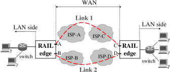
RAIL improves the packet delivery between two remote local area networks (LANs), by connecting them through multiple wide-area paths. The paths are chosen to be as independent as possible, e.g. belonging to different Internet Service Providers. Fig.1 shows an example of two disjoint paths: Link 1 goes through ISP-A and ISP-C, Link 2 goes through ISP-B and ISP-D. (The simplest configuration would be to have both LANs connected to the same two ISPs.) For simplicity, we describe the system using two paths only; the same ideas apply to paths.
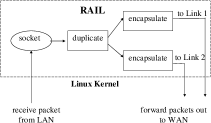
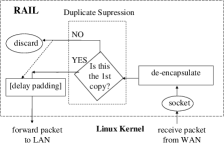
A RAILedge device is required to connect each LAN to the wide-area paths. Each packet that transitions from the LAN to the WAN, via the RAILedge, is replicated at the RAILedge and sent out both WAN links. Copies of the same packet travel in parallel through the different WAN links and eventually arrive at the receiving RAILedge. There are three possibilities: both copies arrive, one copy arrives or no copy arrives. The receiving RAILedge examines every packet coming in from the WAN and suppresses any duplicates; i.e. it forwards the first copy of each packet toward its destination but it discards any copies arriving later.
The result is clear: the probability of both copies being lost is reduced compared to using a single path, and the delay experienced is the minimum of the delay on each path. Overall, the application perceives a virtual RAIL link that is better than the underlying physical links.
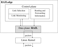
In summary, the RAILedge performs three basic operations: (i) packet duplication (ii) forwarding over all redundant Internet links and (iii) duplicate suppression. RAILedge-RAILedge communication happens over VPN tunnels, to ensure that every RAIL-ed packet is received by the intended RAILedge. We implement tunneling with a simple encapsulation/decapsulation scheme; our header includes the ID of the sending RAILedge and a sequence number, which is used to suppress duplicates at the receiving RAILEdge. All RAILedge operations are transparent to the end-user. The components of a RAILedge device are shown in Fig.2 and the steps taken upon reception of a packet are summarized in Fig.3.
There is a component of the RAILedge that we are not going to examine in this paper: link monitoring and selection. This module is responsible for monitoring the performance of every physical path, computing appropriate quality metrics, and choosing the best subset of paths to constitute the RAIL, over which packets should be replicated. Link monitoring and dynamic selection is a research problem in itself, with extensive and growing literature. In this paper, we do not study dynamic path switching.222Intuitively, we expect that dynamic RAIL switching is a less constrained problem than single-path switching because (i) redundant transmission in a single RAIL provides robustness to short-term problems and (ii) most paths have consistent behavior in the longer time scales. Instead, we focus on (i) evaluating the replication of packets over all paths that constitute the RAIL under study and (ii) on giving recommendations on how to statically select these paths. This is still useful for a typical use of RAIL: initially, the user compares different ISPs and decides which is the best set to subscribe to; after subscription, the user replicates packets over all ISPs.
3.2 Delay Padding
Delay Padding is a mechanism that needs to complement the basic RAIL mechanism when there is delay disparity in the paths. The idea is the following. The default behavior of the receiving RAILedge is to forward the first copy and discard all copies that arrive later. However, this may not always be the best choice when there is significant delay disparity between the two paths. In such cases, one can construct pathological scenarios where the default RAIL policy results in patterns of delay jitter that adversely affect the application.
One example is VoIP: the playout buffering algorithm at the receiver tries to estimate the delay jitter and and adapt to it. This playout algorithm is unknown to us and out of our control; even worse, it is most likely designed to react to delays caused by real single paths, not by virtual RAIL paths. For example, when path 1 is much faster than path 2, then most of the time RAIL will forward copies arriving from path 1. The playout buffer may adapt and closely match it, by choosing a playout deadline slightly above the delay of the path 1. When packets are lost on the fast path, the copies arriving from the slow path will arrive late to be played out - and will be useless. In this scenario, a better use of the two paths would be to “equalize” the delay in the two paths by artificially delaying the packets arriving from the fast path, thus the name “delay padding”. Essentially, delay padding acts as a proxy for playout, located at the RAILedge, and presents the receiver with the illusion of a roughly constant one-way delay. The main differences from a playout algorithm at the end-host is that delay padding does not drop packets that arrive late for playout.
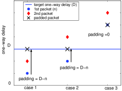
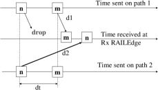
Fig. 4 demonstrates the main idea of delay padding, for packets in the same VoIP flow. The goal is to minimize jitter, i.e. to make all packets experience the same, roughly constant, one-way delay , shown in straight line. For every packet , two copies arrive: the first one is marked with a circle, the second is marked with the diamond. The actual time RAIL forwards the packet is marked with an ”X”. Without padding, RAIL would normally forward the first copy, which incurred one-way delay . With padding, we compare to the target one-way delay .
-
•
In cases 1 and 2: . We wait for additional “padding” time before forwarding the packet.
-
•
In case 3: . We forward the packet immediately, without further delay. (Instead, a playout algorithm at the receiver would just drop the late packets).
The target one-way delay so as to maximize the overall voice quality (MOS): . should be chosen taking into account the statistics of two paths and the delay budget. Adaptation of this value should be allowed only in much larger time scales. We discuss the choice of to optimize , as well as the performance improvement from delay padding, in the section on VoIP evaluation (4.2.1).
Delay padding may prove a useful mechanism for TCP as well. For example, it could be used to remove reordering, caused by RAIL for certain combinations of paths. This is discussed further in the section on reordering (4.1.4) and in the section on the effect of reordering on TCP in particular (4.3.2).
A practical implementation of delay padding for VoIP would require (i) the ability to identify voice packets and keep per-flow state and (ii) calculations of timing in term of relative relative instead absolute one-way delay. An implementation of reordering-removal for TCP, would not necessarily require per flow state; it could just use the sequence numbers on the aggregate flow between the two RAILedges.
3.3 RAIL Prototype and Experimental Setup
In order to evaluate RAIL performance, we developed a RAILedge prototype that implements the functionality described in Section 3.1. Our prototype runs on Linux and consists of a control-plane and a data-plane agent, both running in user space. All routing and forwarding functionality is provided by the Linux kernel. The control plane is responsible for configuring the kernel with static routes and network interfaces. The data plane is responsible for the packet processing, i.e. encapsulation/decapsulation, duplication, duplicate suppression and delay padding. In particular, the kernel forwards each received packet to the data-plane agent, which processes it appropriately and forwards it back to the kernel for regular IP forwarding, see Fig.2.
Our user-space prototype is sufficient for a network connected to the Internet through a T1 or T3 line: Without considering duplicate packets, RAILedge running on a 1.9 GHz CPU with 512 MB of DRAM forwards up to 100,000 minimum-size packets per second (about 51 Mbps) and up to 62,500 average-size (400 bytes) packets per second (about 200 Mbps), while it introduces negligible jitter. For higher-end links, we would need a different prototype that implements the entire data path in kernel space.
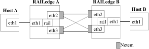
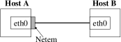
Fig. 5 shows our experimental setup. Two Linux boxes, Host-A and Host-B, communicate through prototype RAILedges A and B respectively. The two RAILedges are connected directly through two of their physical interfaces (eth2-eth2, eth3-eth3), thus simulating the wide-area Links 1 and 2 shown in Fig.1.
We used Netem [21] on interfaces eth2, eth3, to emulate the properties of wide-area networks in a controlled way. The current version of Netem emulates variable delay, loss, duplication and re-ordering. Netem is currently enabled in the Linux kernel. We also emulated WAN links of various bandwidths, using the rate limiting functionality in Linux (iproute2/tc).
4 Performance evaluation
In section 4.1, we show that RAIL outperforms any of the underlying physical paths in terms of network-level metrics, i.e. it reduces loss, delay/jitter, it improves availability and it does not make reordering any worse than it already is in the underlying paths. In sections 4.2 and 4.3 we look at the improvement in terms of application-level metrics for VoIP (MOS) and TCP (throughput); we also look at how this improvement varies with the characteristics, combinations and number of underlying paths.
4.1 RAIL improves network-level metrics
RAIL statistically dominates any of the underlying paths, i.e. it presents the end-systems with a virtual path with better statistics in terms of network-level metrics (loss, delay, jitter and availability). This is intuitively expected. At the very least, RAIL could use just one of the paths and ignore the other; having more options should only improve things. A natural consequence is that any application performance metric calculated using these statistics (e.g. loss rate, average delay, jitter percentiles) should also be improved by RAIL; we found this to be indeed the case in computing metrics for VoIP and TCP. In addition to the statistics, we also looked at pathological sample paths, e.g. that reordering or special patterns of jitter may arise; we show that RAIL does not make things worse than they already are and that delay padding is able to handle these cases.
4.1.1 Loss
Clearly, RAIL decreases the average packet loss rate from , to , for independent paths. One can derive some useful rules of thumb, based on this simple fact.
Number of paths. Given that the actual loss rates are really small in practice, every new independent reduces loss , by at least an order of magnitude. For similar paths () and it is easy to see that the loss probability is a decreasing and convex function of the number of paths (). Therefore, most of the benefit comes from adding the path, and additional paths bring only decreasing returns. However, adding a second path with significant different (smaller) loss rate dominates the product and makes a big difference.
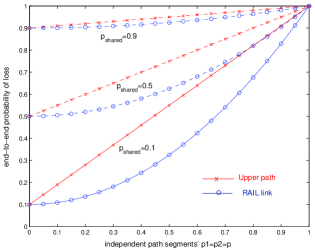
Correlation. In practice, the physical paths underlying RAIL may overlap. E.g. consider two paths that share a segment with loss rate , and also have independent segments with . Loss experienced on any of the single paths w.p. . Loss is experienced over RAIL w.p. . Fig. 6 plots vs. for various values of . Clearly, increases in both and . The lossier the shared part, , compared to the independent part, , the less improvement we get by using RAIL (the curves for and get closer and closer). Therefore, one should not only look at their end-to-end behavior, but also at the quality of their shared part, and choose a combination of paths that yields the lowest overall .
RAIL also decreases the burstiness in loss. Due to lack of space, we omit the analysis and refer the reader to section 4.2.3, for testbed experiments that demonstrate this fact.
4.1.2 Availability
The simplest way to view a “failure” is as a long lasting period of loss, and we can talk about the percentage of time a path spends in failure. Then, the arguments we made for loss in the previous section apply here as well. E.g. for RAIL to fail, both paths must fail; the downtime reduces fast with the number and quality of paths. Table 1 gives a concrete idea on how much RAIL decreases the downtime.
| If both Internet links have | Then the RAIL link has |
|---|---|
| that much bad time: | that much medium time: |
| 10% (2.5 hours/day) | 1% (1.5 hour/week) |
| 2% (3+ hours/week) | 0.04% (2 hours/week) |
| 0.5% (1- hours/week) | 0.0025% (15 min/year) |
| 0.1% (5 hours/month) | (2.5 0.0001% (20 sec/year) |
Note that RAIL not only reduces the time we spend in a “bad period”, but also improves the user experience from “bad” to “medium” during that period. We demonstrate this in detail in the VoIP section (in particular see Table 2).
4.1.3 Delay and Jitter
When a packet is RAIL-ed over two independent paths, the two copies experience one-way delay and , and the packet forwarded by RAIL (the copy that arrived first) experiences . If the cumulative distribution function (CDF) for is , then the delay CDF for RAIL is :
| (1) |
It is easy to see that RAIL statistically dominates any of the two paths. Indeed, the percentage of packets experiencing delay more than over RAIL is , which is smaller than the percentage of packets exceeding on any of the two links (). This means that the entire delay CDF is shifted higher and left, thus dominates and . Any quality metrics calculated based on these statistics (e.g. the average delay, percentiles, etc) will be better for RAIL than for any of the two paths. Rather than plotting arbitrary distributions at this point, we choose to demonstrate the delay and jitter improvement in some practical scenarios considered in the VoIP section (4.2).
4.1.4 Reordering
An interesting question is whether RAIL introduces reordering, which may be harmful for TCP performance? In this section, we show that RAIL does not make things worse than they already are on the underlying paths. RAIL cannot reorder packets if each underlying path does not reorder and does not drop packets. RAIL may translate loss on one path to late arrivals from the other path, which is actually an improvement.
Proposition 1. If each path does not drop or
reorder packets, then RAIL cannot introduce reordering.
Proof. Let us assume that RAIL can reorder packets.
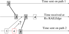
Fig.7(a) shows an example out-of-order
sequence of out of order packets forwarded by the receiving
RAILedge: (3,5,4). The same arguments will hold for any sequence
with . Packets 3 and 5 must have arrived through
different paths (otherwise one of the paths would have dropped
packet 4 or reorder it). Say 3 arrives from the top path and 5 from
the bottom path. Then the copy of 3 sent on the bottom path must
have arrived between 3 and 5 (otherwise RAIL would have forwarded
the bottom 3 copy first). What happened to packet 4 sent on the
bottom path? If it arrived between 3 and 5, then there would be no
out-of-order at RAIL; if it arrived after 5, then the bottom path
would have reordered 4 and 5, which we assumed it is not the case;
and we have assumed that 4 is not dropped either. We reached a
contradiction, which means that RAIL cannot reorder packets if both
paths are well behaving to start with.
Proposition 2. RAIL may translate loss on the faster
path to late arrivals from the slower path. If the inter-packet
spacing at the sender is smaller than
the delay difference of the two paths, then the packets arrive out of order.
Example. In Fig.7(b), we consider
paths 1 and 2, with one-way delay . Two packets and
are sent with spacing between them. If packet is lost on
the fast path, and , then will arrive at the
RAILedge after and the RAILedge will forward them out-of-order.
The larger the delay difference and the smaller the
spacing between packets , the larger the reordering gap.
Fact 3. Better late than never.
Discussion. For VoIP, it does not hurt to receive packets
late, as opposed to not receive them at all.
However, out-of-order packets may potentially hurt TCP performance.
Testbed experiments, in section 4.3.2, show that TCP
performs better when of packets out-of-order, compared to when
of packets lost. Furthermore, the delay padding component is
designed to handle the timely delivery of packets. We will revisit
this fact in section 4.3.2.
4.2 RAIL improves VoIP performance
4.2.1 Voice-over-IP Quality
A subjective measure used to assess Voice-over-IP quality is the Mean Opinion Score (or MOS), which is a rating in a scale from 1 (worst) to 5 (best) [22]. Another equivalent metric is the rating, defined in the Emodel [23]. [23] also provides a translation between and ; in this paper, we convert and present voice quality in the MOS scale only, even when we do some calculations in the scale .
VoIP quality has two aspects. The first is speech quality and it depends primarily on how many and which packets are dropped in the network and/or at the playout buffer. [23, 24] express the speech quality as a function of the packet loss rate, , for various codecs. The second aspect of VoIP quality is interactivity, i.e. the ability to comfortably carry on an interactive conversation; [g.107.g.114] express this aspect as a function of the average one-way delay, , for various conversation types. These two aspects can be added together (in the appropriate scale defined in [23]) to give an overall MOS rating: . This is the metric we will use throughout this section.
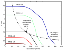
We do not present the details of these formulas in this submission, due to lack of space. The interested reader is referred to the ITU-T standards [23, 24, 25] or to comprehensive tutorials on the subject [26, 27]. What the reader needs to keep in mind is that there are either formulas or tables for , and that . This is a commonly used methodology for assessing VoIP quality, e.g. see [26, 7]. Fig.8 shows contours of MOS as a function of loss and delay based on the data provided in the ITU-T standards, considering G.711 codec and free conversation.
The effect of playout. In the assessment of VoIP, one should take into account the function of the playout algorithm at the receiver, which determines the playout deadline : packets with one-way delay exceeding are dropped. As increases, the one-way delay increases (thus making interactivity worse), but less packets are dropped due to late arrival for playout (thus making speech quality better). Therefore, there is a tradeoff in choosing and one should choose . This tradeoff depicted in Fig. 8 and is also responsible tfor the shape of the curves of Fig.10, which clearly have a maximum at . The value depends on the loss, delay and jitter of the underlying paths as welllas on the delay budget consumed in components other than the playout. Recall that is only a part of the total and that packets arriving late contribute to the total loss ().
The effect of RAIL. In the previous section, we saw that RAIL decreases (i) the loss rate (ii) the average delay and (iii) the percentage of late packets. Therefore, it also improves the which is a function of these three statistics.
4.2.2 Railing VoIP over representative Internet Paths
In this section, we now use realistic packet traces to simulate the behavior of WAN links. In particular, we use the packet traces provided in [28], which are collected over the backbone networks of major ISPs, by sending probes that emulate G.711 traffic.
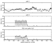
Fig. 9(a) and (b) show the delay experienced on two paths between San Jose, CA and Ashburn, VA. The two paths belong to two different ISPs and experience different delay patterns. Fig.9(c) shows the one-way delay experienced by packets RAIL-ed over these two paths. Packets were sent every 10ms.
Although there is no network loss in these example paths, packets may still be dropped if they arrive after their playout deadline. Because the action of playout is out of the control of RAILedge, we consider the entire range of fixed one-way playout deadlines (out of which 70ms are considered consumed at the end-systems). The resulting is shown in Fig.10 as a function of .333The curve has a maximum which corresponds to that optimizes the loss-delay tradeoff in the overall . Notice that the curve for RAIL is higher then both curves corresponding to individual links, for the entire range of delays considered.
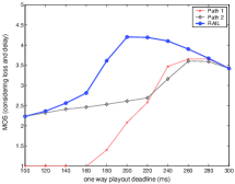
In general, RAIL always improves VoIP quality because it presents the application with a better virtual path in terms of loss, delay and jitter. However, the relative improvement of RAIL vs. the single path depends (i) on the behavior of the two paths and (ii) on the playout algorithm.
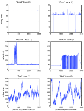
This was just an illustrative example of RAIL over two specific paths. We now consider additional representative traces and their combinations using RAIL. We consider six packet traces from [28], shown in Fig. 11. We call the traces “good”, “medium” and “bad”, to roughly describe the VoIP performance they yield.444E.g. we call the two traces on the top row “good”, because they have almost constant delay, and negligible or no loss. We call the two traces on the medium row “medium” because they are good most of the time, except for a period of high delay/jitter/loss. Finally, the traces in the bottom row have very high delay (up to 400ms!) and jitter.
We then considered pairs of paths for all the combinations of good/medium/bad quality, by choosing one trace from the left and the second trace from the right of Fig.11. Table 2 shows the MOS for each one of the 6 paths, as well as for these 9 combinations using RAIL.555In all cases, a conservative fixed playout deadline of 200ms was considered; 40ms delay has also been added for the end-systems). One can see that the combined link (RAIL) provides one “class” better quality than any of the individual links. For example, if at least one path is good (), then it dominates and the RAIL link is good, regardless of the second link. Two medium links (roughly ) give a good RAIL link() and two bad links () give a medium RAIL link, i.e. there is one class of service improvement. This is intuitively expected, because RAIL multiplexes and uses the best of both paths. In addition, we did in-house informal listening tests: we simulated the transmission of actual speech samples over these traces and we had people listen to the reconstructed sound. It was clear that the RAIL-sample sounded much better.
| RAIL | Path 2 | ||
|---|---|---|---|
| Path 1 | Good-2 | Medium-2 | Bad-2 |
| (4.19) | (3.02) | (1.19) | |
| Good-1 | |||
| (4.21) | 4.21 | 4.21 | 4.21 |
| Medium-1 | |||
| (3.87) | 4.21 | 4.21 | 4.00 |
| Bad-1 | |||
| (1.76) | 4.20 | 3.97 | 3.09 |
Notice, that this quality improvement is in addition to the availability improvement in Table 1: not only RAIL reduces the time spent in “bad/medium” periods, but it also improves the experience of the user during that period, from “bad” to “medium” and from “medium” to “good”.
4.2.3 Testbed experiments for VoIP-over-RAIL
In this section, we use our testbed to demonstrate the improvement that RAIL brings to VoIP quality for the entire range of path conditions. We used Netem to control the loss and delay parameters of each path. We sent probes to emulate the transmission of voice traffic.666200B UDP packets were sent every 20ms (corresponding to G.711 at 64kbps and 20ms packetization: 160B payload and 40B RTP/UDP/IP headers) for 2min duration.
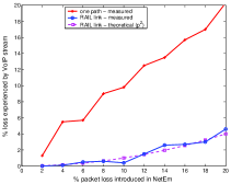
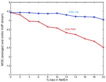
First, we looked at loss rate. We applied uniform loss and the same loss rate from 1 to 20%, which is quite high but may happen during short periods of bursty loss. As expected, the voice stream experiences loss rate when transmitted over RAIL, and over on a single link. Indeed, in Fig.12(a), the measured degrees red line (for a single link) agrees with ; the measured blue line (for RAIL) agrees with the theoretical dashed purple line. This loss reduction results in a speech quality improvement up to 1.5 units of MOS. Fig. 12(b) shows that MOS (averaged over the entire duration) is practically constant when we use RAIL, while the MOS over a single link is decreasing rapidly with increasing loss rate. A side-benefit is that speech quality varies less with time, which is less annoying for the user.
| Number of packets lost in burst | |||||
|---|---|---|---|---|---|
| Loss | Loss Rate | ||||
| Corr. | 10% | 20% | 30% | 40% | 50% |
| 0% | 99/11 | 203/58 | 298/101 | 399/160 | 514/249 |
| 20 | 27/1 | 127/14 | 257/62 | 362/158 | 512/242 |
| 40 | 6/0 | 45/1 | 144/33 | 340/129 | 479/251 |
| 60 | 0/0 | 18/0 | 76/8 | 248/82 | 537/258 |
| 80 | 0/0 | 0/0 | 14/0 | 123/12 | 466/288 |
| Number of bursts | |||||
|---|---|---|---|---|---|
| Loss | Loss Rate | ||||
| Corr. | 10% | 20% | 30% | 40% | 50% |
| 0% | 88/11 | 161/52 | 204/93 | 243/137 | 237/197 |
| 20% | 22/1 | 93 /13 | 185/52 | 197/122 | 230/178 |
| 40% | 5/0 | 37/1 | 99/28 | 175/90 | 198/159 |
| 60% | 0/0 | 13/0 | 50/7 | 124/57 | 164/145 |
| 80% | 0/0 | 0/0 | 4/0 | 53/7 | 100/97 |
| Maximum burst size | |||||
|---|---|---|---|---|---|
| Loss | Loss Rate | ||||
| Corr. | 10% | 20% | 30% | 40% | 50% |
| 0% | 2/1 | 5/4 | 7/2 | 7/3 | 11/3 |
| 20% | 3/1 | 4/2 | 5/3 | 8/7 | 17/5 |
| 40% | 2/0 | 3/1 | 8/4 | 6/5 | 10/7 |
| 60% | 0/0 | 2/0 | 4/2 | 10/4 | 19/7 |
| 80% | 0/0 | 0/0 | 10/0 | 8/2 | 24/16 |
Second, we looked at the burstiness of loss, which is an important aspect because it can lead to loss of entire phonemes, thus degrading speech intelligibility. To control burstiness, we controlled the “correlation” parameter in Netem.777The Netem correlation coefficient does increase the loss burstiness, but does not directly translate to burstiness parameters, such as burstiness duration. An artifact of their implementation [21] is that increasing correlation decreases the measured loss rate (for loss rate¡50%). However, it does not matter: our point is to compare RAIL to a single path, under the same loss conditions We tried all combinations of and measured the following metrics for bursty loss: (i) number of packets lost in burst (ii) number of bursts (iii) average burst size (iv) maximum burst size. In Tables 3,4, 5, we show the numbers measured over one link in regular font, and the numbers measured over RAIL in bold. Clearly, all metrics are significantly reduced with RAIL compared to the single path case, which demonstrates that RAIL reduces loss burstiness. This good property is intuitively expected, as it is less likely that both paths will experience a burst at the same time.
Third, we experimented with delay jitter. We considered two paths with the same mean delay (100ms), and we used Netem to generate delay according to a paretonormal distribution. We generated delay on both paths according to the same statistics. We fixed the mean delay at 100ms for both paths, and experimented with the entire range of delay variability (standard deviation from 10ms to 100ms and delay correlation from 0% to 100%).
In the beginning, we set delay correlation at 0 and increase the standard deviation of delay. We observed that RAIL reduces the jitter experienced by the VoIP stream. This results in less packets being late for playout and thus better speech quality. The exact improvement depends (i) on the delay variability of the underlying paths (captured here by the standard deviation of delay) and (ii) on the playout at the receiver (captured here by the jitter allowed at the playout).
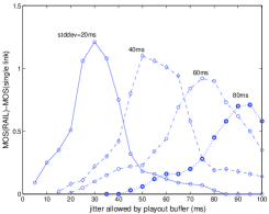
Fig.13 shows the improvement in speech quality (in MOS) compared to a single path, for a range of these two parameters ( 20-80ms and jitter level acceptable at playout 20-100ms). One can make several observations. First, RAIL always help (i.e. benefit); this is because RAIL presents the end-system with a better virtual path. Second, there is a maximum in every curve (every curve corresponds to a certain path delay variability): when the playout is intolerant to jitter, then it drops most packets anyway; when the playout can absorb most of the jitter itself, then the help of RAIL is not needed; therefore, RAIL provides most of its benefit, in the middle - when it is needed to reduce the perceived jitter below the acceptable threshold for playout. Finally, the entire curve moves to the right and lower for paths with higher delay variability.
In addition, we experimented with delay correlation (which will result in several consecutive packets arrive late and get dropped in the playout) and we observed that RAIL decreased this correlation by multiplexing the two streams. Finally, we experimented with RAIL-ed VoIP and several non-RAILed TCP flows interfering with it. The idea was to have loss and delay caused by cross-traffic rather than being artificially injected by Netem. RAIL brought improvement in the same orders of magnitude as observed before.
4.2.4 Delay Padding
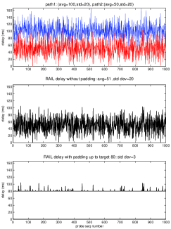
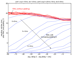
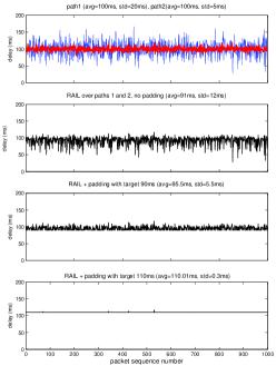
The delay padding algorithm, described in section 3.2, acts as a proxy playout at the receiving RAILedge: it artificially adds delay (“padding”) in order to create the illusion of constant one-way delay. In this section, we use matlab simulation to demonstrate the effect of padding. Fig.14 considers the case when the two paths differ in their average delay; this can be due to e.g. difference in propagation and/or transmission delay. Notice the difference between (b)-RAIL without padding and (c)-RAIL with padding. Fig.15 shows that the larger the disparity between the two paths, the more padding is needed to smooth out the stream. Fig. 16 considers the case when two paths have the same average delay but differ significantly in the delay jitter, e.g. due to different utilization. Fig. 16(a) plots the delay on the two paths on the same graph; Fig. 16(b) shows what RAIL does without padding; Fig. 16(c) and (d) show that the stream can be smoothed out by adding more padding. The appropriate amount of padding should be chosen so as to maximize the overall MOS - as discussed in section 4.2.1.
4.3 RAIL improves TCP performance
In the section 4.1, we saw that RAIL statistically dominates the underlying paths in terms network-level statistics. Therefore, performance metrics computed based on these statistics, such as the average throughput, should be improved. In section 4.3.1, we analyze the throughput of long-lived TCP flows, and we show that indeed this is the case. However, there may be pathological cases, e.g. when reordering falsely triggers fast-retransmit; this is what we study in section 4.3.2, and show that -for most practical cases- RAIL helps TCP as well .
4.3.1 Analysis of long-lived TCP-over-RAIL
A simple formula. Let us consider two paths with loss rate and round-trip times: (, ), respectively, and w.l.o.g. . The simple rule of thumb from [29] predicts that the long-term TCP throughput for each path is: . What is the long-term TCP throughput using RAIL over these two paths? Following a reasoning similar to [29], we find that:
| (2) |
| (3) |
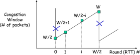
Proof. Fig. 17 shows the simple steady-state model considered in [29]. The network drops a packet from when the congestion window increases to packets. The congestion window is cut in half (), and then it increases by one packet per round-trip time until it reaches packets again; at which point, the network drops a packet again and the steady-state model continues as before. Let us look at a single congestion epoch.
For that simple model, the number of packets sent during the congestion epoch is . For the packet to be lost , both copies sent over the two paths must be lost. Therefore, the loss rate is and . The only difference from [29] is that the round-trip time as perceived by TCP-over-RAIL is no longer constant, but it depends on whether a packet is lost on any of the paths. Provided that the packet is received on at least one path, which has prob. ), we are still in the same congestion epoch and
| (4) |
Therefore, the conditional expectation for RTT is given by Eq.(3); and the TCP throughput over RAIL is on average:
| (5) |
Essentially, RAIL appears to the TCP flow as a virtual path with loss rate and round-trip time . Notice that there are two factors to take into account in Eq.(2): a multiplication in loss () and an averaging in delay E[RTT]. The loss for RAIL is smaller than any of the two links: . The same is not true for the delay which is a weighted average: .
Implications. Let us now use this simple formula to study the sensitivity of tcp-over-RAIL throughput to the characteristics of the underlying paths.
Fact 1. TCP throughput is better over RAIL than over any of the two paths: and .
Proof. First, consider that . Then, the RAIL link is equivalent to a single link with , which is better than any of the two by an order of magnitude. What happens when ? It is easy to see that RAIL is better than the slower path (2), because RAIL has both smaller loss and shorter RTT than the slow path (2):
| (6) |
Is RAIL better than the faster path (1) as well? RAIL is better in terms of loss but worse in terms of delay (). It turns out that the multiplicative decrease in loss dominates the averaging in delay.
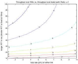
In Fig.18, we consider , we fix and consider the full range of and . We plot the ratio between the throughput for TCP-over-RAIL vs. TCP-over-fast-link.
| (7) |
We see that tcp does 4-10 times better over RAIL than over the fast link (1), for all practical cases: loss rates up to 10% and difference in delay up to 100ms. Indeed, the difference in cannot be exceed some tens of milliseconds (e.g. due to propagation or transmission ), and should be really small, except for short time periods.
How many paths? For n paths with characteristics , where , and following similar derivations, we find that:
| (8) |
The multiplicative factor dominates the averaging E[RTT]. Also large RTTs have discounted contributions. For , is a convex increasing function of , which implies that adding more paths of similar loss rate, improves throughput but with decreasing increments.
4.3.2 Testbed Experiments on Reordering and TCP
In section 4.1.4, we saw that RAIL does not introduce reordering if both paths are well behaving, but may convert loss on the fast path to late - and at the extreme even out-of-order packets under some conditions (). It is well known that reordering may have a reverse effect on TCP, as it falsely triggers the fast retransmit. In this section, we use testbed experiments to show that, even in cases that RAIL converts loss to reordering, this is actually beneficial for TCP.
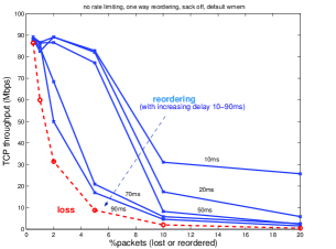
Recall that RAIL does not cause reordering, it only translates loss to reordering. Therefore, the fair question to ask is not how “TCP does with reordering vs. without reordering” but instead “how TCP does with of packets arriving out-of-order vs. of packets being lost”.
Fact 3-revisited. Better late than never (and the earlier the better). We used the simplified testbed shown in Fig.19 to inject a controlled amount of loss and reordering, using Netem, on a single TCP flow. Fig.20 shows the results of the comparison. First, we introduced x% of loss, ranging from 0 to 20%; the TCP throughput is shown in dashed line. Then we introduced x% of reordering for a range of reordering gaps/delays, i.e. the packets arrive 10-90ms later than they should; the resulting TCP throughput is shown in a separate bold line for each delay value. We see that TCP performs much better with reordering than with loss, therefore it is indeed better to receive packets “late than never”. Not surprisingly, the less the delay in delivery, the better the performance.
Furthermore, TCP has today several default options to deal with reordering: including SACK, DSACK and timestamps. We found that turning SACK on further improved the performance of TCP under reordering in Fig.20. In summary, we expect RAIL to help TCP for all practical cases, i.e. for small loss rates and delay differences between the paths in the order of 10-50ms. As an extreme measure, one can use the delay padding mechanism not only for voice, but also as a TCP ordering buffer to completely eliminate reordering.
5 Future Directions
We envision a RAIL-network architecture, where RAILedges are control points that use path redundancy, route control and application-specific mechanisms, to improve WAN performance.
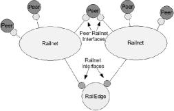
A first extension has to do with topology. So far, we considered two RAILedge devices connecting two remote sites via multiple redundant links. We envision that this can be generalized to a virtual multipoint network or RAILnet, where multiple edge networks are reliably interconnected to each other, as shown in Fig.21. Each participating edge network is located behind its own RAILedge, and each RAILedge pair communicates over at least two Internet links. The Railnet interface represents the local point of attachment to a Railnet and should present itself as a regular interface to a multi-access subnet.
Second, we are interested in combining the proactive replication of RAIL with some kind of route control, in particular (i) selection of the right subset of physical paths within the same RAIL and also (ii) dynamically switching among them. In this paper, we focused on the first part (i.e. at combinations of paths with various characteristics, at different number of paths, at paths that are similar or different from each other) and tried to give recommendations on how to statically select among them. The second aspect is dynamic switching among sets of paths. We expect this to be a less constrained than single-path switching, because (i) redundant transmission is robust to short-lived problems and (ii) physical paths tend to have consistent behavior in the long time scales. Therefore, RAIL should relieve much of the urgency in dynamic path switching decisions.
One could further enhance the functionality of RAILedge. So far, we focused on replication of packets over multiple paths. Several other functions can be naturally added on an edge network device, including monitoring and path switching, compression, quality-of-service mechanisms, protocol specific acceleration. For example, one could decide to RAIL part of the traffic (e.g. VoIP or critical applications) and use striping for the remaining traffic; this could correspond to RAIL-0 in the raid taxonomy [15].
There are some additional interesting questions, we are currently pursuing as a direct extension of this work. First, we continue to study TCP over RAIL, using more accurate TCP models, and considering also short-lived connections; we are also working on a modification of our delay-padding algorithm, to remove reordering at the receiving RAILedge. Second, we are investigating the effect of RAIL on the rest of the traffic. E.g. when there is significant disparity in bandwidth, we expect RAIL-ed TCP to cause congestion on the limited-bandwidth path. Furthermore, what is the interaction between competing RAILs? Finally, it would be interesting to explore the benefit of adding additional RAILedges in the middle of the network.
The RAILnet architecture can be incrementally deployed by gradually adding more RAILedges. If widely deployed, it has the potential to fundamentally change the dynamics and economics of wide-area networks.
6 Conclusion
We proposed and evaluated the Redundant Array of Internet Links (RAIL) - a mechanism for improving packet delivery by proactively replicating packets over multiple Internet Links. We showed that RAIL significantly improves the performance in terms of network- as well as application-level metrics. We studied different combinations of underlying paths: we found that most of the benefit comes from two paths of carefully managed; we also designed a delay padding algorithm to hide significant disparities among paths. RAIL can be gracefully combined with and greatly enhance other techniques currently used in overlay networks, such as dynamic path switching. Ultimately, it has the potential to greatly affect the dynamics and economics of wide-area networks.
References
- [1] D.Andersen, H.Balakrishnan, F.Kaashoek, R.Morris, “Resilient Overlay Networks,” in Proc. of ACM SOSP, Banff, Canada, Oct. 2001.
- [2] A. Akella, J. Pang, B. Maggs, S. Seshan and A. Shaikh, “A Comparison of Overlay Routing and Multihoming Route Control”, in ACM SIGCOMM 2004, Portland, OR.
- [3] A. Akella, B. Maggs, S. Seshan, A. Shaikh and R. Sitaraman, “A Measurement-Based Analysis of Multihoming”, in ACM SIGCOMM 2003, Karlsruhe, Germany.
- [4] RouteScience Tech. Inc., “Adaptive Networking Software”.
- [5] InterNAP, http://www.internap.com/.
- [6] FatPipe, http://www.fatpipeinc.com/.
- [7] S. Tao, K. Xu, A. Estepa, T. Fei, L. Gao, R. Guerin, J. Kurose, D. Towsley, and Z.L. Zhang,“Improving VoIP Quality via path switching,” in Proc. IEEE INFOCOM 2005, Miami, FL, March 2005.
- [8] S. Tao, K. Xu, Y. Xu, T. Fei, L. Gao, R. Guerin, J. Kurose, D.Towsley, and Z. Zhang, ”Exploring the Performance Benefits of End-to-End Path Switching’, in Proc. of IEEE ICNP 2004, Berlin, Germany, Oct. 2004.
- [9] R. Keralapura, C.-N. Chuah, N. Taft and G. Iannaccone, “Can coexisting overlays inadvertently step on each other?”, , in the Proc. of IEEE ICNP, Boston, MA, Nov. 2005.
- [10] R.Gao, C.Dovrolis and E.W.Zegura, “Avoiding Oscillations due to Intelligent Route Control Systems,” to appear in the Proc. of IEEE INFOCOM 2006, Barcelona, Spain, Apr. 2006.
- [11] F. Kelly and T. Voice, “Stability of end-to-end algorithms for joint routing and rate control,” in Computer Communication Review 35:2 (2005) 5-12.
- [12] H. Han, S. Shakkottai, C.V. Hollot, R. Srikant and D. Towsley, “Overlay TCP for Multi-Path Routing and Congestion Control,” presented in ENS-INRIA ARC-TCP Workshop, Paris, France, Nov. 2003
- [13] Y. Liu, H. Zhang, W. Gong, D. Towsley, “On the Interaction Between Overlay and Underlay Routing,” in Proc. IEEE INFOCOM 2005.
- [14] L. Qiu, Y.R. Yang, Y. Zhang and S. Shenker, “On Selfish Routing in Internet-Like Environments,” in Proc. of ACM SIGCOMM 2003, Karlsruhe, Germany, Aug. 2003.
- [15] D. A. Patterson, G. Gibson, and R. H. Katz, “A Case for Redundant Arrays of Inexpensive Disks (RAID)”, in Proc. of ACM SIGMOD 1988, pp.109-116, Chicago, IL, 1988.
- [16] R. Barlow, F. Proschan, “The Mathematical Theory of Reliability”, Siam’s Classics in Applied Math. Series, 1996.
- [17] J. Apostolopoulos, “Reliable Video Communication over Lossy Packet Networks using Multiple State Encoding and Path Diversity”,in Proc. of Visual Communications and Image Processing, Jan. 2001.
- [18] J. Apostolopoulos, T. Wong, W. Tan, and S. Wee, “On Multiple Description Streaming with Content Delivery Networks”, in IEEE INFOCOM 2002, June 2002.
- [19] Y. Liang, E. Setton, and B. Girod, “Network-Adaptive Video Communication Using Packet Path Diversity and Rate-Distortion Optimized Reference Picture Selection,” Journal of VLSI Signal Processing Systems for Signal, Image, and Video Technology, vol. 41, no. 3, Nov. 2005.
- [20] E. Steinbach, Y. Liang, and B. Girod, “A Simulation Study of Packet Path Diversity for TCP File Transfer and Media Transport on the Internet,”, in Proc. of IWDC 2002, Capri, Italy, Sept. 2002.
- [21] Netem: http://linux-net.osdl.org/index.php/Netem.
- [22] ITU-T Recommendation P.800, “Methods for subjective determination of transmission quality”, August 1996.
- [23] ITU-T Recommendation G.107, “The Emodel, a computational model for use in transmission planning”, Dec. 1998.
- [24] ITU-T Recommendation G.113, “Transmission impairments due to speech processing”, Feb. 2001.
- [25] ITU-T Recommendation G.114,“One way transmission time”, May 2000.
- [26] A.Markopoulou, F.Tobagi, M.Karam, “Assessment of VoIP quality over Internet backbones,” in Proc. of IEEE INFOCOM 2002.
- [27] R.G.Cole, J. Rosenbluth, “Voice over IP performance monitoring”, Computer Communications Review, V.4, no.3, Apr. 2001.
- [28] A.Markopoulou, F.Tobagi, M.Karam, “Loss and Delay Measurements of Internet Backbones,” A.Markopoulou, F.Tobagi, M.Karam, in Computer Communications 2005.
- [29] J. Mahdavi, S. Floyd, “TCP-Friendly Unicast Rate-Based Flow Control”, Technical note sent to the end2end-interest mailing list, Jan. 1997.