A Capacity Achieving and Low Complexity Multilevel Coding Scheme for ISI Channels
Abstract
We propose a computationally efficient multilevel coding scheme to achieve the capacity of an ISI channel using layers of binary inputs. The transmitter employs multilevel coding with linear mapping. The receiver uses multistage decoding where each stage performs a separate linear minimum mean square error (LMMSE) equalization and decoding. The optimality of the scheme is due to the fact that the LMMSE equalizer is information lossless in an ISI channel when signal to noise ratio is sufficiently low. The computational complexity is low and scales linearly with the length of the channel impulse response and the number of layers. The decoder at each layer sees an equivalent AWGN channel, which makes coding straightforward.
1 introduction
High bandwidth efficient communication systems require the use of multilevel or multi-phase constellations. The major difficulty of applying a coded modulation scheme, such as trellis coded modulation [1] and bit-interleaved coded modulation [2], to an intersymbol interference (ISI) channel is receiver complexity. Clearly, the optimal joint equalization and decoding scheme, such as [3], leads to extremely high complexity. Even in the context of Turbo equalization [4], a suboptimal yet very efficient iterative approach, the optimal BCJR-based equalizer has exponential complexity in both channel memory and constellation size. Various equalizers with reduced complexity, such as minimum mean square error (MMSE) equalizer, are proposed in [5], [6] at a cost of degraded performance.
This paper proposes a coded modulation scheme for a static ISI channel with capacity achieving performance and very efficient computation. The idea is to do multilevel coding (MLC) [7], [8] and multistage decoding with a linear mapping [9] at the transmitter and a separate linear MMSE (LMMSE) equalization and decoding at the receiver. Minimal computation is required and will scale linearly with channel length and the number of layers. The number of layers is large so that, by the central limiting theorem, the output of the mapper approaches a Gaussian distribution. More importantly, this paper shows that an LMMSE equalizer in an ISI channel with non-white Gaussian noise is information lossless when the signal to noise ratio (SNR) is sufficiently low. Therefore, given a fixed total power, a large will effectively drive each layer to operate at a low SNR region, in which, the proposed separate LMMSE equalization and decoding is not only efficient but also optimal. The task of code design is also simple since the decoder at each layer sees an equivalent AWGN channel. Consequently, the scheme can achieve the i.i.d. Gaussian capacity of an ISI channel if each layer employs a capacity achieving code.
This paper is organized as follows. Section 2 presents the MLC scheme with the LMMSE equalization algorithm. The optimality of the scheme is discussed analytically in Section 3, and also is numerically demonstrated in Section 4. Some design issues, such as power allocation and rate design, are discussed in Section 4. The result shows that if the power of each level is properly allocated, only a moderate number of layers is required for the overall system to approach the channel capacity.
2 System Model
This section presents the overall system of the MLC with LMMSE equalization as shown in Fig. 1. Let be the scaled version of a sequence of identically, independently and uniformly distributed binary sequences, such that or with equal probability for all . A total of such mutually independent BPSK sequences, for , are summed to produce the transmitted sequence , where . In general, each BPSK layer has a different power level and the total power is . The ISI channel is modelled as a time-invariant causal FIR filter with order and an impulse response that is known to both the transmitter and the receiver. Let be the AWGN. The received signal is written as
| (1) |
The receiver employs multistage decoding, i.e., it successively equalizes and decodes BPSK layers from layer 1 to layer . Once a layer is correctly decoded, its effect on the channel output can be completely removed by filtering it with and subtracting the resulting waveform from the received signal. After cancelling the interferences of all decoded layers, the current layer treats the undecoded layers as noise and employs an LMMSE filter to compute the likelihood ratio of the input bit. A memoryless channel decoder uses these likelihood ratios to decode the codeword and feed the hard decision to the next layer. This receiver of layer is shown in Fig 2.
Consider the decoding process of the th stage. We assume the receiver has correctly decoded layer 1 to , i.e. for all and . The decoded layer interference cancelled signal at layer is
| (2) |
The receiver uses an FIR LMMSE filter of order to estimate from a vector of channel output for any . Using vector notation, define a Toeplitz matrix and its block partition as
| (3) |
where , and . Furthermore, define . Therefore,
| (4) |
where , and . In (4), the first term is due to the desired input, the second term is the ISI, the third term is the interference from undecoded layers and the last term is AWGN. From linear estimation theory, the LMMSE filter at layer in vector form is
| (5) |
The LMMSE estimate of is thus
| (6) |
From (4), (6) can be equivalently written as
| (7) |
where is the equivalent channel gain and
| (8) |
is the equivalent channel noise. From the central limiting theorem, the equivalent noise has a Gaussian distribution such that , where
| (9) |
Thus, the likelihood function of is computed from
| (10) |
The subsequent decoder decodes the codeword solely based on the set of likelihood ratios. Its hard decision is feedback to the next stage.
3 Optimality
In this section, Theorem 1 and 2 will establish that given a sufficiently large number of layers, the proposed multilevel coding and its receiver, which sequentially (non-iteratively) performs LMMSE equalization and decoding, can approach the ISI channel capacity with i.i.d. Gaussian input.
The key observation is that, at any layer, if the signal to interference plus noise ratio (SINR) is sufficiently low, the LMMSE filtered channel retains the original ISI channel capacity. Theorem 1 shows this for Gaussian input and Gaussian interference. Theorem 2 extends this results to the -layered MLC scheme with BPSK inputs. Throughout this paper, the vector notation will be used.
Theorem 1
Consider an ISI channel with input , interference and noise ,
| (11) |
where is the channel impulse response, and , and are i.i.d. Gaussian random sequences with zero mean and variance , and respectively. Let be the output of the LMMSE filter, then
| (12) |
Theorem 2
Let be the ISI channel capacity with Gaussian inputs. Let be the capacity of proposed -layer multilevel coding with LMMSE equalization, where the input of each layer is i.i.d. BPSK of power and the LMMSE filter has infinite length. If the total power is finite and the power allocation at each layer satisfies
| (13) |
where is the variance of AWGN, then
| (14) |
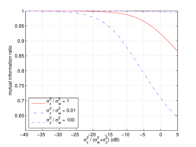
The convergence of (12) as is illustrated in Fig. 3 for different values of and a random -tap ISI channel. The LMMSE used is a -tap FIR filter as designed according to (5). It is clearly shown in Fig. 1 that the convergence happens whether the AWGN or interference dominates. This is important for the MLC scheme because the interference to noise ratio varies for different layers.
Although the optimality in Theorem 2 is established for a large number of layers, next section will show how the power of each layer can be allocated to minimize the number of required layers.
4 Practical design issues and numerical results
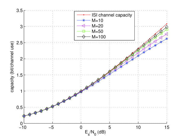
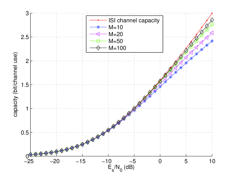
MLC with multistage decoding can approach capacity if and only if each lay uses a capacity achieving code whose rate is equal to the layer’s capacity [8]. The proposed MLC employs a linear mapping, and we are free to allocate the power of each layer. Consequently, the rate of each layer can be designed flexibly. A good power allocation scheme is important in our case. This section discusses these practical design issues and presents numerical results. Two channels are used for simulation, a short channel , and a randomly generated long channel
4.1 Achievable rate at each layer
Since we are constrained in receiver structure, we do not intend to calculate the capacity of each layer. Instead, we will compute its achievable rate under the given LMMSE equalizer. The computation is based on the statistics of the bit probabilities computed by an actual receiver from a simulated channel output sequence. No Gaussian assumption is made here. The achievable rate of the layer sub-channel is given by
| (15) |
where the a posteriori probability can be derived from (10) as
| (16) |
and is evaluated using Monte Carlo simulation. Thus, the overall achievable rate of the multilevel scheme is .
4.2 Power allocation
We consider three power allocation schemes as follows.
1) Equal power. In this scheme, each layer has the same power. Fig. 4 and Fig. 5 show the achievable rate of the equal power MLC with .
2) Equal distance. This power allocation scheme can produce a constellation with equal distance. For example, to produce a uniformly distributed -ary ASK sequence, the power of each layer should satisfy . This can be extended to a QAM constellation if each dimension transmits an independent ASK sequence. Note, at moderate to high SNR, this power allocation scheme is not capacity achieving since each layer still operates at moderate SINR.
3) Equal rate. This scheme allocates the power in such a way that the achievable rate at each layer is identical, i.e., , where is some fixed rate. A simulation based numerical procedure is required to determine the power of each layer, starting from layer to layer . Fig. 6 and Fig. 7 compare the achievable rate of the equal rate MLC to the i.i.d. Gaussian capacity for both a short and a long ISI channel.
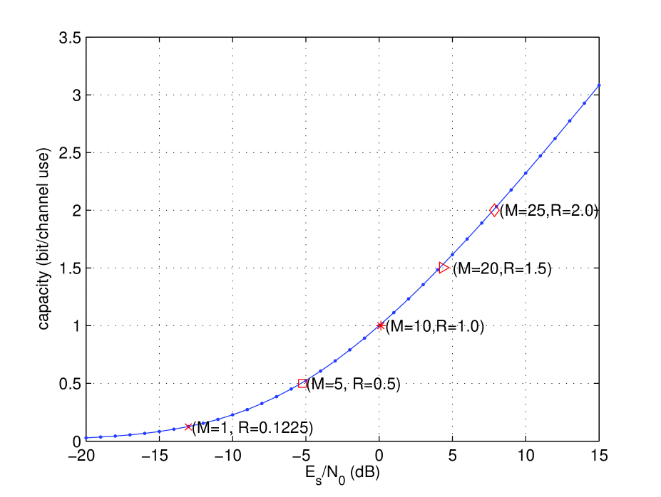
In summary, both equal power and equal rate power allocation can achieve channel capacity, while equal distance power allocation can generate desired ASK or QAM constellations but does not achieve capacity. Furthermore, equal rate power allocation requires fewer layers than the equal power scheme to achieve the same capacity.
4.3 Code Design
A common tool for designing the component codes at each layer is equivalent channel model [8], [10]. In the proposed MLC with LMMSE filtering, the equivalent channel, as seen in (7), is simply an AWGN channel with BPSK input. Thus, many existing capacity achieving codes, such as low-density parity-check (LDPC) codes [11], and their design technique, e.g., density evolution [12], can be applied in a straightforward way. The above code design process can be further simplified using equal rate power allocation. In this case all equivalent channels of all layers are equivalent to an AWGN channel with a given capacity . Therefore, we only need to design a single code for this AWGN channel and apply the code and its encoder/decoder pair to all layers. Note, a random interleaver will be used for each layer to avoid decision feedback error propagation in this case.
The second task is to assign a code rate for each layer. When a capacity achieving code with infinite block length is available, we can use capacity rule [8] so that the code rate at layer is equal to the achievable rate . When code is not capacity achieving, the code rate must be smaller than the achievable rate. Furthermore, since the MLC scheme relies on perfect decoding of all layers, the code rate must be designed so that all layers will have a low BER at a given overall SNR simultaneously. Other techniques such as random coding bound [8] can also be applied to design the rate.
5 Extension and conclusion
This paper proposes an MLC and LMMSE equalization scheme and shows that it can achieve channel capacity for ISI channels with i.i.d Gaussian inputs. A further extension to achieve the ultimate “water-filling” capacity is also straightforward by incorporating a spectral shaping filter at the transmitter and a corresponding LMMSE equalizer at the receiver. The scheme is computationally efficient and is especially attractive for systems with severe ISI.
The principle of MLC with linear mapping and multistage decoding can be applied to correlated or block fading channels with unknown channel states. The fundamental idea is using the decoded layers as training symbols. The receiver then estimates the channel based on the training symbols. As long as the power of each layer is very small, estimation and decoding can be decoupled without loss. This is under current investigation.
References
- [1] G. Ungerboeck, “Channel coding with multilevel/phase signals,” IEEE Trans. Info. Theory, vol. IT-28, pp. 55 – 67, Jan. 1982.
- [2] G. Caire, G. Taricco, and E. Biglieri, “Bit-interleaved coded modulation,” IEEE Trans. Info. Theory, vol. 44, no. 3, pp. 927 – 946, May 1998.
- [3] P. R. Chevillat and E. Eleftheriou, “Decoding of trellis-encoded signals in the presence of intersymbol interference and noise,” IEEE Trans. Communications, vol. COM-37, pp. 669 – 676, July 1989.
- [4] M. Tuchler, R. Koetter, and A. Singer, “Turbo equalization: principles and new results,” IEEE Transaction on Communications, vol. 50, no. 5, pp. 754–767, May 2002.
- [5] A. Dejonghe and L. Vandendorpe, “Turbo-equalization for multilevel modulation: an efficient low-complexity scheme,” in ICC 2002. IEEE International Conference on Communications, April 2002, pp. 1863 – 1867.
- [6] P. Magniez, B. Muquet, P. Duhamel, and M. de Courville, “Improved turbo-equalization with application to bit interleaved modulations,” in Proc. Asilomar Conf. on Signals, Systems and Computers, Conterey(CA), USA, Oct. 2000, pp. 1786 – 1790.
- [7] H. Imai and S. Hirakawa, “A new multilevel coding method using error-correcting codes,” IEEE Trans. Info. Theory, vol. 23, no. 3, pp. 371 – 377, May 1977.
- [8] U. Wachsmann, R. F. H. Fischer, and J. B. Huber, “Multilevel codes: theoretical concepts and practical design rules,” IEEE Trans. Info. Theory, vol. 45, no. 5, pp. 1361 – 1391, July 1999.
- [9] L. Duan, B. Rimoldi, and R. Urbanke, “Approaching the AWGN channel capacity without active shaping,” in Proceedings. 1997 IEEE International Symposium on Information Theory, June 1997, p. 374.
- [10] J. Hou, P. H. Siegel, L. B. Milstein, and H. D. Pfister, “Capacity-approaching bandwidth-efficient coded modulation schemes based on low-density parity-check codes,” IEEE Trans. Info. Theory, vol. 49, no. 9, pp. 2141 – 2155, Sept. 2003.
- [11] R. G. Gallager, “Low density parity check codes,” MIT Press, 1963.
- [12] T. J. Richardson, A. Shokrollahi, and R. L. Urbanke, “Design of capacity-approaching irregular low-density parity-check codes,” IEEE Trans. Inform. Theory, vol. 47, no. 2, pp. 619–637, Feb. 2001.