Investigations of Process Damping Forces in Metal Cutting
Abstract
Using finite element software developed for metal cutting by Third Wave Systems we investigate the forces involved in chatter, a self-sustained oscillation of the cutting tool. The phenomena is decomposed into a vibrating tool cutting a flat surface work piece, and motionless tool cutting a work piece with a wavy surface. While cutting the wavy surface, the shearplane was seen to oscillate in advance of the oscillation of the depth of cut, as were the cutting, thrust, and shear plane forces. The vibrating tool was used to investigate process damping through the interaction of the relief face of the tool and the workpiece. Crushing forces are isolated and compared to the contact length between the tool and workpiece. We found that the wavelength dependence of the forces depended on the relative size of the wavelength to the length of the relief face of the tool. The results indicate that the damping force from crushing will be proportional to the cutting speed for short tools, and inversely proportional for long tools.
keywords: metal cutting, chatter, process damping, shear plane dynamics.
AMS classification numbers: 74S05,74H45,74H15.
* Communicating author. Current address: Dept. of Mathematical Sciences, The University of Montana, Missoula, MT 59812
Running title: Process Damping Forces in Metal Cutting
1 Introduction
In this paper we investigate the forces produced in dynamic metal cutting, where either the chip load varies in time, or the tool itself oscillates. Chatter is a consequence of an instability in cutting that leads to self-sustained vibrations of the tool, hence it is composed of both an oscillating tool and an undulating workpiece surface. We separate chatter into these two pieces by using finite element software for metal cutting developed by Third Wave Systems, Inc. called AdvantEdge, to simulate the processes. AdvantEdge is a validated software package that integrates advanced dynamic, thermo-mechanically coupled finite element numerics and material modeling appropriate for machining processes. The simulation software provides accurate estimates of thermo-mechanical properties of the machining process such as cutting forces, chip morphology, machined surface residual stresses, and temperature behavior of the tool and workpiece.
Recently Third Wave Systems has developed two new modules, one with custom work piece geometry and another with a vibrating tool, that increase the range of cutting conditions that can be simulated. The custom work piece geometry module allows for the design of arbitrary cutting surfaces in addition to the traditional flat surface. We study the effect of a varying chip load through a cut with this module, observing interesting shear plane dynamics and varying thrust and cutting forces. With the vibrating tool module, the cutting tool can be horizontally or vertically vibrated at a user specified frequency and amplitude. This allows us to investigate the effect of contact between the material and the relief face of the cutter, which generates a kind of process damping.
In section 2 we examine the forces involved in cutting a workpiece with a sinusoidally varying surface and, as a consequense, a sinusoidally varying depth of cut. In section 3 we use the vibrating tool module to investigate process damping on the relief face of the tool during chatter. In section 4 we summarize our findings and suggest avenues for further research.
2 Wavy Surface Runs
The work piece geometry we use has a sinusoidal top surface which was generated by replacing the horizontal flat surface of the standard geometry with a sine function. The wavelength of the sinusoid was based on scaled parameters from experimental chatter measurements [8]. To ensure the feed was always greater than zero, the feed was set to be larger than the peak to valley amplitude of the sinusoid (3 mil). All these AdvantEdge runs were performed on AL 7050 with a carbide tool with a 10 degree rake angle, and cutting edge radius of 0.7874 mil and cutting speed of 2680 SFM. Altogether three sets of runs were performed with three different feeds: 6,9, and 12 mil.
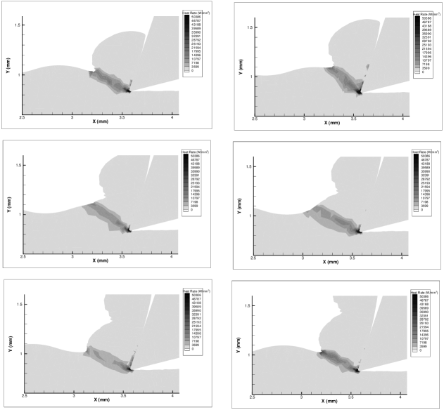
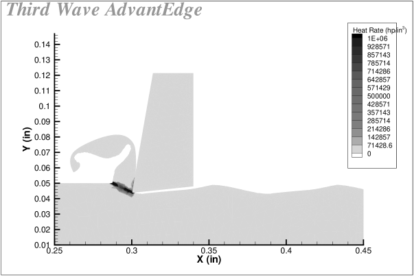
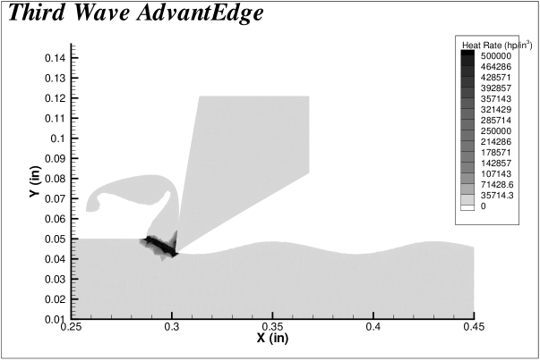
From the animations of the Third Wave runs we saw that the shear plane angle during the cut oscillates as the tool moves through sinusoidally varying depth of cut (see figure 1). The shear plane, denoted by the band of higher heat rates extending from the tool tip, is seen to lift up smoothly and shorten as the tool anticipates the thickest part of the chip. After reaching its maximum slope, the band snaps down and elongates to connect the tool tip with the point ahead on the surface that has the smallest chip thickness. The shear plane continues to extend between the tool tip and this minimum until that point, now a part of the chip, is crushed into the point on the surface with maximum chip thickness. The cycle repeats as the tool continues to encounter the oscillating chip thickness. The experiments we performed were designed to explore the effect of variation in depth of cut, shear plane angle, and shear plane length on the instantaneous cutting forces.
2.1 Wavy Surface Force Predictions
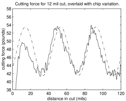
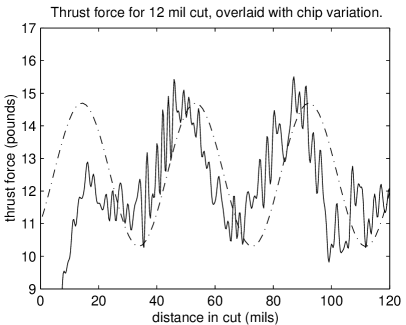
Our first observation is that the measured forces in (cutting) and (thrust), while oscillating at the same frequency as the chip thickness, lead it in phase. To illustrate this we plot the thrust and cutting force through the cut, overlaid with a sine wave of the same frequency and phase as the chip thickness, see figures 2 and 3. (The amplitude and DC offset of the sine wave were scaled to match the force for illustration).
The phase lead makes sense after analyzing individual frames in the simulations. (See figure 1.) The chip begins to bunch up and hence offer more resistance, which creates larger cutting forces prior to the maximum in the chip thickness. The forces drop before the tool tip encounters the next minimum of the chip thickness, in reaction to the shearplane snapping down to meet the minimum, which causes the chip to narrow down and offer less resistance.
This phase lead of the force over the chip thickness has been observed in experiments carried out in Dr. Philip Bayly’s lab at Washington University (for representative publications from Dr. Bayly’s group see [2, 3, 4]). A tube cutting experiment with a vibrating tool was set up on a lathe, creating an essentially single degree of freedom system with one dominant mode. Tests were performed to determine the frequency response (FRF) of the cutting system, and these FRF were used to parameterize a single degree of freedom model for the cutting process. This model was developed in part by Brian Whitehead, who describes in his thesis [1] an attempt to include friction on the rake face of the tool by incorporating a weighting function that models the variation of forces as the chip slides up the rake face of the tool, after Stépán [5]. One of the parameters of the model is the contact length, , between the tool relief face and chip. With positive the weighting functions, once incorporated into the frequency domain model, act as low-pass filters, and induce a lag in the force behind the uncut chip thickness. Upon fitting this model with the tube cutting experiment FRF, they determined that the best fit came with using a negative value, essentially making the forces on the tool anticipate the chip thickness. This does not make sense if is considered to be the contact length on the rake face, but with negative the force is being integrated over a region out in front of the tool, which induces the phase lead of the force over the uncut chip thickness. We believe that this is a manifestation of the shearplane oscillation effect we see in the Third Wave cutting simulations.

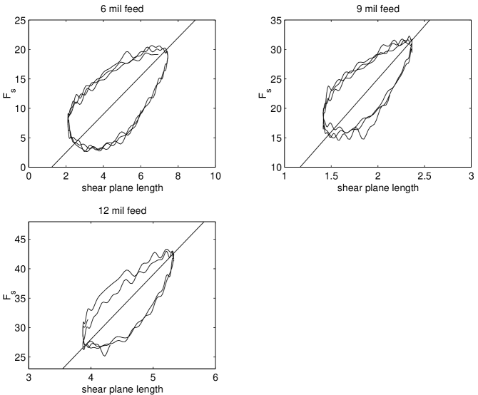
It is plausible that while the forces lead the chip thickness, they may be in phase with the shearplane length, following a model popularized by Ernst and Merchant [6], that assumes that the forces will be proportional to the shear plane length. The Merchant model predicts that specifically the shear plane force ) is linearly dependent on the shear plane area, so , where is the shear stress involved in cutting the material, is the cutting width, and is the length of the shear plane, which is oriented at the angle (refer to figure 4). Also from the figure note that , where is the total force on the tool. To determine we rely on the traditional decomposition of into vertical and horizontal components, and , the radial or thrust, and the tangential or cutting, forces respectively. If the angle that makes with the horizontal is given by , then . The AdvantEdge program computes and , which also gives us a measure of the total cutting force as the tool moves through the cut, since , as well as the angle . We can measure the shear plane length , and the angle , for each step in the run, and since , we can test the Merchant prediction:
| (1) |
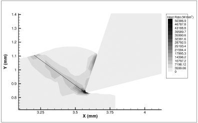
The shearplane length was measured directly from the animation frames, where visualizations of the heat production are best for identifying the shearplane region. This is subject to obvious error through the identification of a line that could be called the shearplane. We chose to measure a line that started at the tip of the tool and ended at the surface of the workpiece, parallel with the contours of heat production. See figure 5 for an example. The shear plane length oscillates along with the undulations in the surface of the workpiece, though not necessarily with the same phase. Following this observation, the shearplane length as the tool moves through the workpiece was least squares fit to a sine wave with the same wavelength as the wavy surface. The result of this exercise for the 12 mil feed run is plotted in figure 6, and the fitted expression is
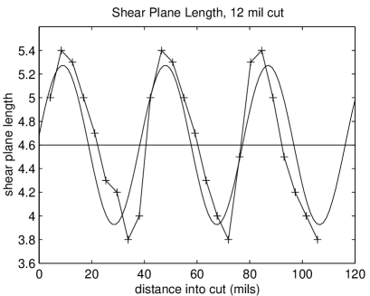
The units on shearplane length are arbitrary, and vary with the three runs examined in this section. The important feature is the phase of the oscillation.
The shearplane angle can be measured and fit in a similar way, the result is presented in figure 7, and the fitted expression is
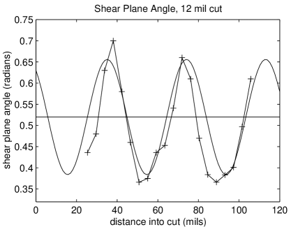
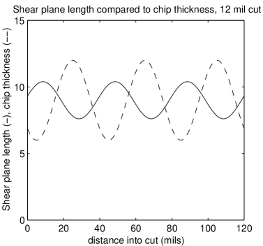
Similar fits were performed for the 6 and 9 mil cuts, and the units are radians. We also observe that the shearplane length oscillation leads the chip thickness oscillation by a noticeable amount, see figure 8.
We compute and for each of the three runs as a function of distance into the cut (). Expression (1) implies that , so we conducted a least squares fit to with the expression , the result is presented in figure 9. The shear plane force is seen to lag the shear plane length, which fits with the observation that while the shearplane force leads the chip thickness, the shearplane length leads the chip thickness by an even greater amount, leading to the lag in shearplane force with respect to the shearplane length.
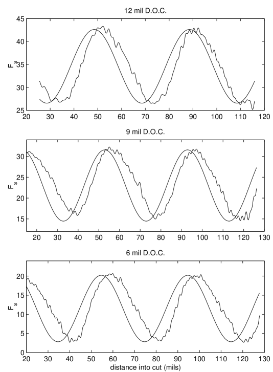
Also note that we fit the force not with , as is specified by Ernst and Merchant, instead it is a linear fit offset by a constant. This indicates that there must be a nonlinear region near , a roll-off of the function so that when . This by itself does not contradict the Merchant model, which was meant to apply only in steady cutting finite chip thickness regimes. However, the Merchant formula does fail to completely capture the behavior of the forces in this dynamic situation.
This procedure suggests plotting the data parametrically against to determine if this linear fit is appropriate, see figure 10. In this format it is clear that the shearplane force depends on something in addition to , since it is a multi-valued. The fitted line is drawn for comparison for each of the three runs.
The direct measured forces, and can also be compared with the shearplane length oscillation during the run. The result is presented in figure 11, for the 12 mil chip thickness run.
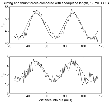
The cutting force also lags the shearplane length, similar to , predictably since the cutting force is the largest component of the total force. The thrust force, however, comes very close to matching the oscillation of the shearplane length, a fact that could be explored further.
To conclude this section, we would like to comment on an idea presented in Wellbourne and Smith [7]. They computed an expression for the cutting force involved in cutting a wavy surface by assuming that the force was proportional to the shear plane length also. However, they were limited to estimating the shearplane length by computing the length of a line, oriented at a constant slope, as it intercepts a sine wave (see figure 12).
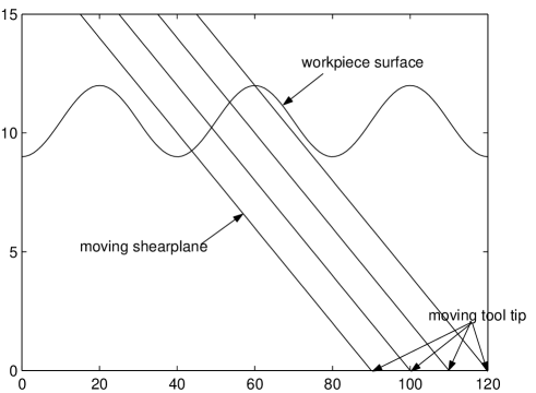
The length can be found by solving a transcendental equation (the intersection of the moving line and a sine wave) numerically for varying shear plane angles (figure 13).
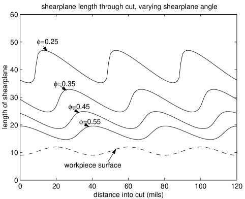
From this you can see that the length leads the oscillation of the chip load, how much depending on the shear plane angle. The oscillation also becomes more triangular as the angle is decreased, it will have a discontinuity when the multiple roots to the transcendental equation appear, that is, for small enough shearplane angles.
These effects certainly play into the form of the forces determined with experimentally measured shear plane lengths. But there are several confounding factors: the shear plane angle is not a constant, and more importantly, the surface itself is deformed during a cut, and the simple intersection of a line and a sine wave does not give the correct shear plane length, as we saw in the animations, see figure 1.
3 Analyzing Crushing Forces
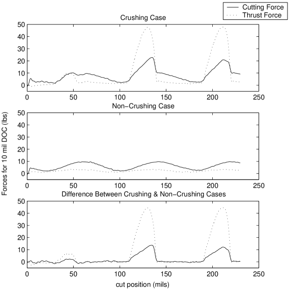
As described in the Introduction, the new Third Wave module that allows the tool to oscillate either horizontally or vertically during a cut gave us an opportunity to explore the forces involved when the relief face of the cutting tool impacts the workpiece. In our simulations to investigate relief face crushing the cutting tool was vibrated sinusoidally in the vertical direction with a 3 mil amplitude and varying frequencies. Two simulations were performed to calculate the crushing force for each set of cutting parameters, identical in all ways except for the relief angle of the tool. In one simulation, the relief angle was small enough that the entire relief face came into contact with the workpiece, causing the crushing of the workpiece at the relief face of the tool. In the other simulation, the relief angle was made large enough so that there was no contact between the relief face of the tool and the work piece.
To illustrate, a snapshot of a crushing run is shown in figure 14, where the tool has come into contact with the workpiece during the downstroke of the tool and left a flattened region in its otherwise sinusoidal path. This should be compared with a run with the relief angle drawn up from 6 degrees to 25 degrees, figure 15, where the tool tip leaves a sinusoidal workpiece surface in its wake. Assuming the forces involved in material removal and crushing combine linearly, the crushing force can be resolved by subtracting the forces from two such runs. The exercise is illustrated in figure 16, where the material being cut is AL7050, with a tool with rake angle of 10 degrees and cutting edge radius of 0.5 mils. In the two runs the wavelength of the oscillation is 80 mils, corresponding to a cutting speed of 2680 SFM and vibration frequency of 6.7 kHz. The nominal feed is 1 mil, and vibration amplitude is 3 mil. The spatial wavelength of the undulating cut is equal to the ratio of the vibration frequency to the cutting speed , that is . We focused our investigations on the vertical or thrust force in what follows.
We found that the relief edge length, relative to the wavelength of the oscillation, was critical in determining the behavior of the crushing force in these runs. Therefore we ran simulations with tool relief lengths of 10 mil, 30 mil and 100 mil, which were much smaller, somewhat smaller, and much larger than the range of wavelengths tested. The results are summarized below.
3.1 Crushing force simulations
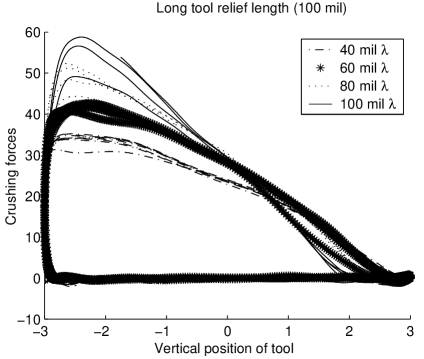
Once again the AdvantEdge runs were performed on AL 7050 with a carbide tool with a 10 degree rake angle and cutting edge radius of 0.7874 mils. The cutting speed was chosen to be 2680 SFM, and vibration frequencies near 13.4 KHz, and amplitudes of 3 mils, typical of an axial-torsional vibration mode for a twist drill ([8]). In total we did 24 runs: 12 crushing, 12 no crushing. For each length of tool relief face (10, 30 and 100 mils) we ran four wavelengths: 40, 60, 80 and 100 mil. We found plotting the crushing force vs. the vertical amplitude of the tool during a run a useful way of visualizing the data. In figures 17-19 these results are presented for each tool relief length, with the varying wavelength runs plotted together for comparison. The general form of each plot is the same, during the downstroke of the tool, as expected, the crushing force increases up the angled portion of the loop, i.e. the loops are traversed counterclockwise with increasing time. Near the end of the downstroke the force begins to decrease, and drops to zero abruptly as the tool begins its trip back up to the top of the oscillation. During this phase the force is zero and the portion of the loop along the displacement axis is traversed. Immediately after the top of the oscillation is reached and the downstroke begins, the force starts to increase again, and another cycle is initiated.
The three sets show a qualitative difference in shape, and a quantitative difference in maximum force achieved relative to wavelength of the oscillation. The long relief length tool demonstrates the most easily understood force loop: the force increases approximately linearly as the tool moves into the material, reaching a maximum close to the lowest point of the traverse. In the short relief length tool runs the force increases approximately linearly until about one third of the way down, when it flattens out. The short tool relief length is saturated at this point: is has come into contact with as much material as it can, it cannot impact more length as it moves down. The intermediate length tool runs have a shorter flat region that depends on wavelength, with longer wavelengths showing some flattening.
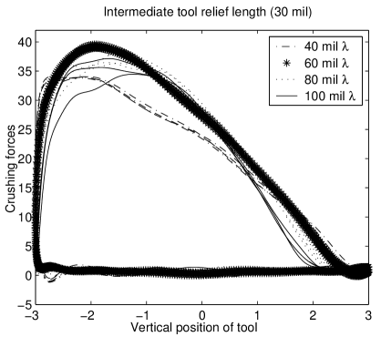
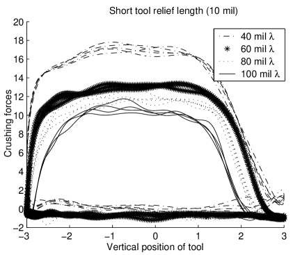
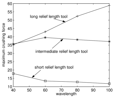
The quantitative difference between the three sets of runs concerns the dependence of the maximum force value vs. wavelength of oscillation. In Whitehead [1], a model for process damping due to rubbing on the relief face is proposed that depends inversely on the wavelength of the vibration, based on a suggestion by Tobias [9]. This translates to a term in his linear model that is directly proportional vibration velocity (which depends directly on vibration frequency) and inversely proportional to cutting speed. In figure 20 we plot the maximum force for each run vs. wavelength in the three cases. Though the data is too sparse to fit any detailed model, it is clear that the force is inversely proportional to the wavelength only in the short relief length runs, the long relief length runs demonstrate a direct dependence on wavelength, and in the intermediate length runs the maximum force appears to be indifferent to wavelength. The dependence of the damping on cutting speed and vibration frequency thus will depend on the length of the relief face relative to the vibration wavelength, and given that chatter vibrations are mainly high frequency, the long tool data will be the most relevant for estimating chatter process damping.
3.2 Crushing force modeling
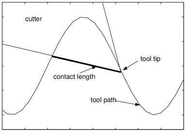
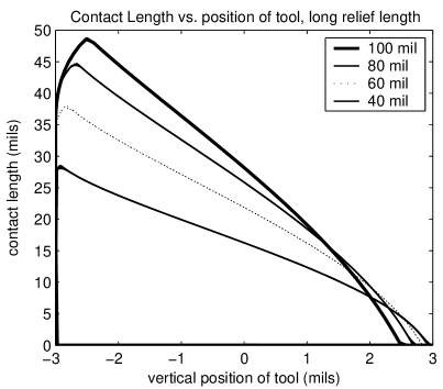
The magnitude of the crushing force will most certainly depend on the amount of contact between the relief face of the tool and the material. We can analytically model the variation of the contact during a crushing thrust of the tool by determining the contact length, as it depends on frequency of the oscillation, height of oscillation and the cutting speed. The contact length at each point along the cut can be calculated from the intersection of a tool edge with the work piece (see figure 21). The sinusoid in the figure is the path that the tool takes during an oscillation, the chip is not shown in the diagram. A small program in MATLAB calculated this intersection length in the figures that follow.
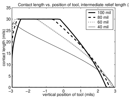
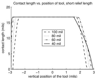
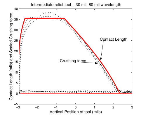
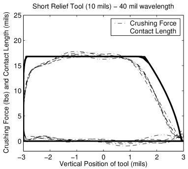
The contact length during an oscillating cut is plotted vs. vertical position of the tool tip, see figure 22. This representation can be directly compared to the force vs. vertical position plot for the 3rd Wave run with a 100 mil relief length tool, figure 17. The contact length and the force have similar dependence on wavelength, both increase with increasing wavelength at the bottom of the downstroke of the tool (the highest point on the loop). There is also a “roll-over” at the top of the downstroke, where the shorter wavelength force/contact length does not begin to grow as soon as the longer wavelength case. This is a consequence of the relative slope of the tool path to the relief angle of the tool. A similar diagram for the short relief length (10 mil) tool is shown in figure 24. The contact and the crushing forces in this case saturate when the tool relief length is fully engaged with the workpiece, but an obvious difference between the two is the invariance the maximum contact length shows with respect to wavelength. The maximum forces, however, decrease with increasing wavelength for the short tool.
With this evidence in mind we can attempt to fit the crushing force data from the experiments with a model that has a linear dependence on contact length. If is the contact length, is the crushing force, and and are fitted via least squares. The results depend on the wavelength of the oscillation and the relief length of the tool, and are tabulated below.
Long relief length tool (100 mil):
| wavelength (mils) | fitted line | error (lbs) |
|---|---|---|
| 40 | Y = 1.102 * X + 0.397 | 2.34 |
| 60 | Y = 1.132 * X - 1.539 | 3.75 |
| 80 | Y = 1.184 * X - 9.698 | 3.88 |
| 100 | Y = 1.305 * X - 20.493 | 3.74 |
Intermediate relief length tool (30 mil):
| wavelength (mils) | fitted line | error (lbs) |
|---|---|---|
| 40 | Y = 1.002 * X + 3.628 | 3.02 |
| 60 | Y = 1.431 * X - 6.472 | 2.54 |
| 80 | Y = 0.963 * X - 7.128 | 2.47 |
| 100 | Y = 0.977 * X - 7.877 | 2.62 |
Short relief length tool (30 mil):
| wavelength (mils) | fitted line | error (lbs) |
|---|---|---|
| 40 | Y = 0.548 * X + 1.501 | 0.84 |
| 60 | Y = 0.234 * X + 1.350 | 0.51 |
| 80 | Y = 0.207 * X + 1.484 | 0.12 |
| 100 | Y = 0.167 * X + 0.957 | 0.33 |
The slope constant in the linear relationship gives the scale factor between force (in lbs) and contact length (in mils) and thus has units lbs/mil of contact length. This conversion factor varies somewhat within runs (mean and standard deviation are , for the long, intermediate and short relief length runs, respectively) The y intercept is determined by nonlinearity in the data at the top and bottom of the cycle in the data, which causes the linear region to move up or down.
To illustrate these results we plot the scaled contact length vs. vertical position of the tool along with the crushing force for a comparable run, for the three different relief lengths and varying oscillation wavelengths (figures 22,23, and 24). The long tool force loop shows a close fit with contact length, except near the top of the oscillation when the contact length grows more quickly from zero. The intermediate tool shows a better fit with data at top of the oscillation, though the force does not flatten out in the same way as the contact length. The short tool forces are undercut the contact length, the contact length grows more quickly at the top of the oscillation, again, and the forces begin to decrease from the plateau before the contact length comes down. All these point to additional factors coming into play in the prediction of crushing forces. The assumption of linear dependence on contact length holds primarily for the mid-region of the downstroke of the tool, excluding the lift-off at the bottom and turn-around point at the top.
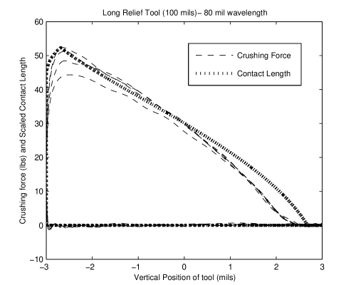
To illustrate these results we plot the scaled contact length vs. vertical position of the tool along with the crushing force for a comparable run, for the three different relief lengths and varying oscillation wavelengths (figures 25, 26, and 27). The long tool force loop shows a close fit with contact length, except near the top of the oscillation when the contact length grows more quickly from zero. The intermediate tool shows a better fit with data at top of the oscillation, though the force does not flatten out in the same way as the contact length. The short tool forces are undercut the contact length, the contact length grows more quickly at the top of the oscillation, again, and the forces begin to decrease from the plateau before the contact length comes down. All these point to additional factors coming into play in the prediction of crushing forces. The assumption of linear dependence on contact length holds primarily for the mid-region of the downstroke of the tool, excluding the lift-off at the bottom and turn-around point at the top.
4 Discussion and Conclusions
Our investigations with Third Wave simulations were designed to isolate different effects present during regenerative chatter vibrations in metal cutting: the vibration of the tool and the oscillatory variation in the chip thickness. The tool vibration feature of the package was used to investigate process damping due to crushing of the workpiece material on the relief face of the tool, and the custom workpiece feature allowed us to set up a sinusoidally varying chip-load. Simulations with the later demonstrated an oscillation of the shear plane as the tool progressed, and we found that the cutting, thrust and shear plane forces all were in advance of the chip thickness. The shear plane force, proposed to be directly dependent on shear plane length by Ernst and Merchant [6], was found to lead the shear plane length as well, as the forces anticipated the decrease in chip load. This anticipation is due primarily to the deformation of the chip as it encounters the tool, not surprizingly the process is more complex than predicted during dynamic cutting.
An important cause of process damping is the interaction of the relief face of the cutter with the workpiece material. Here we studied the thrust forces involved in such damping by running an oscillating tool in AdvantEdge for a variety of oscillation wavelengths and tool relief lengths. We found that the wavelength dependence of the force was determined by the length of the relief face of the cutter relative to the wavelength of the oscillation: for long relative relief length the maximum force increased with increasing wavelength, for short relative relief length it decreased, and for intermediate relative relief length the dependence was indeterminent. This expands the intuition of Whitehead et al., [1] who used a process damping model that depended inversely on wavelength, as it would for a short tool. Since the wavelength of the oscillation equals the cutting speed divided by the oscillation frequency, this means the damping is proportional to the cutting speed for short tools, and inversely proportional to the cutting speed for long tools. This, however, assumes that the frequency of oscillation is independent of cutting speed, which is most likely not the case, given the form of the linear stability diagrams for regenerative chatter (for an example related to this study see [8]).
We also found that the force depended linearly on contact length between the relief face of the tool and the workpiece material during the downward stroke of the tool. Other factors come into play during the initial moments of the downward stroke, and through the “lift-off” of the tool from the trough of the oscillation. This suggests that this form of process damping can be explained purely geometrically, where the relevant factors are oscillation amplitude and relative size of relief length to wavelength. Incorporating this into a model that would determine stability of the steady cutting state to oscillations would not be straight-forward, however, since the damping itself depends on the wavelength of the instability induced (typically the wavelength is determined by the physical parameters of the system, not a priori).
In summary, this research highlights the importance of dynamic and nonlinear effects on instabilities in metal cutting, even in the case of orthogonal cutting. Forces that act in anticipation of chipload increases and process damping that depends in a complicated way on vibration frequency are examples of effects that could be studied further, both in the laboratory and with large scale and predictive computer modeling.
Acknowledgements
This work was supported in part by the National Science Foundation (DMS-0104818) and the Mathematics and Computing Technology Group, The Boeing Company, Bellevue, WA.
References
- [1] Whitehead, B., The Effect of Process Damping on Stability and Hole Form in Drilling, Master of Science Thesis, Sevier Institute of Technology, Washington University, St. Louis, (2001).
- [2] Bayly, P.V., S. A. Metzler, A.J. Schaut, and K.A. Young, Theory of torsional chatter in twist drills: model, stability analysis and comparison to test, ASME J. Man. Sci. & Eng., 123 (4), 552-561 (2001).
- [3] Bayly, P.V., K.A. Young and J.E. Halley, Analysis of tool oscillation and hole roundness error in a quasi-static model of reaming, ASME J. Man. Sci. & Eng., 123 (3), 387-396 (2001).
- [4] Bayly, P.V., M.T. Lamar, and S.G. Calvert, Low frequency regenerative vibration and the formation of lobed holes in drilling, ASME J. Man. Sci. & Eng., 124 (2), 275-285 (2001).
- [5] Stépán, G., Delay differential equation models for machine tool chatter, Dynamics and Chaos in Manufacturing Processes, F. Moon, ed., Wiley and Sons, 165-192 (1998).
- [6] Ernst, H. and M.E. Merchant, Chip formation, friction and high quality machined surfaces, Trans. Am. Soc. Met., 29, 299-378 (1941).
- [7] Wellbourne, D.B, and Smith, J.D., Machine Tool Dynamics, an Introduction, Cambridge University Press, Cambridge, U.K., p. 31 (1970).
- [8] Stone, E., and A. Askari, Nonlinear models of chatter in drilling processes, Dynamical Systems, 17 (1) 65-85 (2002).
- [9] Tobias, S.A., Machine Tool Vibration, J. Wiley, New York, (1965).