On the Effect of Fading on Ad-hoc Networks
Abstract
Most MANET (Mobile Ad hoc NETwork) research assumes idealized propagation models. Experimental results have shown significant divergence from simulation results due to the effect of signal fading in realistic wireless communication channels. In this paper, we characterize the impact of fading on protocol performance. We first study the effect of fading on MAC performance and show that its effect can be dominating. One of our important conclusions is that eliminating RTS/CTS packets results in more effective operation under fading. We also identify an unfairness problem that arises due to backoffs in the presence of fading. Moreover, fading results in several subtle interactions between the MAC and routing layers. We identify several of these problems and make observations about effective approaches for addressing them. For example, the criteria for determining the best path should not only consider the link status but also the link order. In addition, because routing protocols rely on MAC level transmission failure (when the retry limit is exceeded), route failure errors are often generated unnecessarily. Finally, because MAC level broadcasts are unreliable, they are especially vulnerable to fading. We analyze these effects and outline preliminary solutions to them.
I Introduction
Mobile Ad hoc NETworks (MANETs) are networks made of mobile nodes that self-configure and collaborate to forward packets among each other without the benefit of an access point. These networks are especially important when infrastructure is unavailable (e.g., unplanned networks, in remote areas, or after a disaster), or expensive. In such networks, each node must play the role of a router as well as a station.
Most existing MANET research assumes idealized wireless propagation: nodes have a fixed transmission range and all receivers within this range receive a transmission correctly (assuming no collision occurs). However, due to fading and multipath effects this assumption deviates significantly from reality: wireless transmission can suffer deep fading (drop in power level) with very small changes in location, or in time. Fades of 20dB (the signal dropping to 1% of its ideal value) are not rare [1]. These properties have profound implications on protocol performance and designs that make many of the decisions taken under idealized assumptions invalid. Wireless transmission success ratio drops with the distance between sender and receiver. This behavior leads to several interactions within the MAC layer and across layers, some of which are subtle.
The effect of fading on MANET behavior has been observed and studied empirically; Decouto et al show that, contrary to idealized models, fading has considerable effect on link state – using shortest path as a measure of path quality can therefore be misleading [2]. Moreover, the packet loss rate varies from link to link (as a function of the distance and the surrounding environment); the quality of a hop must be made visible to the routing protocol to enable effective route selection. To capture this effect, they propose ETX: a link cost metric that is a function of the forward and backward delivery ratio on a link [3]. Other link cost metrics have also been proposed to allow fading sensitive route selection [4]. Draves et al conducted an experimental analysis of these metrics and found that ETX performs best [5]. Integrating these effects into a routing architecture has been studied as well. Woo et al explored a routing architecture for managing wireless propagation vagaries in a sensor network environment [6]. One of their main conclusions is that using ETX as a route metric provides stable routing performance. However, the static sensor network environment allows specialized routing and link estimation solutions that are difficult to generalize to a MANET environment. Draves et al propose Link Quality Source Routing (LQSR), an extension of the Dynamic Source Routing Protocol to address the problems that arise due to fading [5]. In addition to allowing path selection based on link quality, LQSR has several additional interesting features such as continuous monitoring of path quality and higher route stability.
Other effects of fading have also been observed and are reviewed throughout this paper. The majority of the work is experimental. More specifically, problems are observed in real testbeds and solutions are proposed to address them. As a result most of the work is focused on routing implications. In this paper, we take a complementary bottom up approach to this problem. We start with an analysis of the problem at the MAC layer. As a result, we capture some problems that occur in the MAC layer itself as well as problems that affect the upper layers. The bottom up approach provides a more systemic and comprehensive evaluation of the effect of fading on protocol performance than experimental testbed analysis. The contributions of the paper also include the identification of new problems that arise due to fading and the development of initial solutions for them.
We first characterize the effect of fading on the performance MANET protocols analytically and using simulation using a slow fading propagation model. One of our contributions is to show that Collision Avoidance (Request to Send (RTS)/ and Clear to Send (CTS) packets of IEEE 802.11) is harmful to performance under fading and not that beneficial for collision avoidance. Moreover, we identify an unfairness problem that occurs due to unbalanced backoffs that occur due to fading losses. In addition, we outline the implications of this behavior on the routing layer and propose preliminary solutions to the problems.
The remainder of this paper is organized as follows. Section II explains some background information. Section III analyzes the basic effect of fading on MAC layer performance. Section IV makes the case for eliminating Collision Avoidance from MAC protocols. Section V outlines the unfairness and inefficiency problems occurring due to backoff under fading. In Section VI we present high level descriptions of additional problems that occur at upper layers. Finally Section VII presents some concluding remarks.
II Background
II-A Wireless Propagation
In a typical terrestrial environment, the transmitted signal reflects off of surrounding objects, refracts when travelling through obstacles and suffers diffraction due to sharp edges. Moreover, doppler shifts occur due to moving objects. As a result, many echos of the transmitted signal are received with different delays and power-levels depending on the path they took. Together, these result in large transient flucuations in the power level: this is known as fading [1].
The details of wireless propagation are beyond the scope of this paper. Briefly, fading of a wave can be explained by slow fading (e.g., due to dominant shadowing objects) and fast fading (due to numerous smaller objects) [7]. Slow fading occurs over time periods generally longer than a packet length; thus, we may consider a single transmission power value per packet. Alternatively, small scale fading, or fast fading, occurs within the packet. Fast fading model considers the effect of scattered wave (also called by multi-path reception model). The Rayleigh or Ricean statistical distributions have been shown to capture this effect well. Ricean is used when there is a line of sight path between sender and receiver and Rayleigh is used when there is none.
With advanced modulation technologies (specifically, spread spectrum/CDMA) and specialized antennas (such as the RAKE receiver), the effect of small scale fading can be almost eliminated in the RF frequency bands used for wireless communication. Thus, we focus only on slow fading.
II-B Propagation Models
There are three kinds of propagation models typically used in MANET protocol simulation and analysis. The simplest model is Free Space model. The energy is in inverse proportion of square of distance. This model is too simple to apply to realistic terrestrial setting. Therefore, a more realistic model (called Two Ray Ground), which considers the reflection of signal against the ground as well as directly propagated signal, is used. At short distance, only the directly propagated signal matters. Thus, the path loss exponent (), which determines the (exponentiated) rate of attenuation of the signal with distance, is 2; i.e., the power drops with the square of distance. However, after a cross-over distance which depends on the height of the antennas, both the direct component and the ground reflected component combine to create a higher path loss factor (typically assumed to be between 3 and 4). The Two-Ray Ground Model is also idealized; it does not consider the fading effects described above.
We use a fading propagation model in this paper that statistically models slow fading. Although this model is known (e.g., it is available in the NS-2 [8] and Qualnet simulators [9]), it is not typically used. In this model, the path loss is a random variable that has a log-normal distribution, with a mean equal to the expected two-ray ground path loss. More specifically, the signal power consists of two parts: the mean power and the fading effect. The mean received power at a communication distance is the idealized power as a function of that distance is calculated as follows,
| (1) |
where is a reference distance that is a function of the antenna height. The path loss equation in formula dB is eq 1. is the ideal path loss exponent (i.e., without considering fading).
The second component models the transient fading effect. Received power is adjusted by a log-normal random variable . The fading is modeled as a gaussian distribution with average 0, and standard deviation . The overall received power ius expressed as,
| (2) |
Because random variable , the range no longer represents a discrete threshold with “in-range” or “out-of-range” nodes. Rather, it is now continuous: packets in the ideal range may be lost and packets outside the ideal range may be received. The probability of correct reception decreases with distance accoding to Eq. 2. While this model is available in simulators such as NS-2 and QualNet, it is almost never used in MANET network level research. We use it as the basis for our analysis.
Rather than focusing on the impact of and on protocol behavior, we pick representative values and use them to evaluate the impact of fading on MANET protocols. Clearly, the impact can be amplified or lessened with different and values.
II-C Fading Model Limitations
The model we use is statistical and has several limitations. Recent observations have shown that transmission losses at the link layer are not generally independent [10]. Moreover, a limitation of the model we consider is that the PDF of the received power is strictly a function of distance, making links symmetric. However, fading is known to cause asymmetric link qualities. Since IEEE 802.11 requires symmetric communication, it is likely to suffer as a result of asymetric link qualities. The effect of Asymmetry on routing behavior has been considered but we do not know of any analysis of the microeffects that arise due to asymmetry [11]; this is a topic of future work. There is a need for developing more accurate propagation models that capture these effects. However, we believe the simple fading models we use are sufficient to identify the effects and problems we discuss in this paper: more refined models will certainly enable more accurate characterization of their effect.
Another limitation of the model is that we do not consider the effect of multi-rate MAC protocols. Recent versions of IEEE 802.11 recognize the effect of fading on link quality [12]. To combat this effect, the use multi-rate transmission where the modulation scheme used is adapted dynamically and at the packet level to match the link quality (high rate when link quality is high and lower rate when it is low) [13]. While this mitigates the effect of fading, it comes at a high cost because the interframe spacing, backoff periods and the rate negotiation headers have to be transmitted at the lowest rate [14]. We focus on single transmission rate MAC protocols. While multi-rate MACs help to mitigate the effect of fading, low-cost, low-power radios continue to be single rate [15, 16, 17]. These radios are the most likely candidate for use in embedded and low power devices.
III Basic Effect of Fading on the MAC Protocol
In this section, we analyze the effect of fading on the MAC layer. The effects identified in this section are not intended to be comprehensive. The fading model used is idealized and the scenarios are simple. Other intricate interactions may arise in more realistic environments. Our aim is to emphasize that fading must be treated as a first class problem in MANET MAC protocol design. Furthermore, in the next Section, we argue that it must also be carefully designed for in higher level protocols.
The NS-2 network simulator is used for all simulation experiments in this paper [8]. We use a path loss component of 3 (typical range is 2–6 in real environments). For the log-normal fading model we set (recall that 20dB fades are not uncommon; a standard deviation of 4dB is rather conservative). The transmission power is set such that the ideal range is 250 meters.

Figure 1 shows a simulation trace of the received power at distance 220 meters. Note that when the receiving power drops below the receiver sensitivity threshold, the transmission is lost. Because we use a slow fading model, the same receive power is assumed per packet.
III-A Preliminaries
In fading model, the received power depends on path loss and the log-normal component . Eq ( 2) can be simplified as the following: , where and . Recall that has normal distribution . Ignoring interference, the probability of correct transmission is the probability of the received power being higher than the receiver sensitivity threshold (, which is a radio constant). This can be directly computed as P().

Figure 2 shows the computed delivery ratio vs. that of the idealized two ray ground model. Clearly fading has a large effect on the packet delivery ratio as the distance between the sender and the receiver increases. Although we show our results as function of distance, they should be considered of in terms of delivery ratio (which in our model has a one to one mapping per Figure 2). In real testbeds, the packet reception probability is influenced by the surrounding environment and its PDF is not only a function of distance.
This observation confirms the need for routing protocols to be aware of the link quality. The figure also shows the delivery ratio obtained from simulation which not surprisingly, is very close to the calculated ones. Since the link level transmission ratio in the simulation is being generated with the same distribution used in the analysis, the simulation represents a Monte Carlo solution with packets dropped according to the propagation model equation.
III-B Effect of Packet Retransmission
Packet retransmission is used to increase reliability and to recover both from transmission errors and collisions. In this section we analyze the effect of retransmission on packet delivery ratio and show that under low delivery retransmission is in fact counterproductive. Moreover, we analyze the effect of retransmission on packet delay. We do this using the retransmission algorithm of IEEE 802.11.
In IEEE 802.11, there is a Short Retry Limit (SRL) and Long Retry Limit (LRL). A transmission is classified as long or short based on its length relative to a fixed threshold. A transmission below the threshold is counted against the SRL, while a transmission above it is counted against both SRL and LRL. SRL and LRL are 7 and 4 respectively.
III-B1 Effect on Packet Delivery Ratio
Successful delivery of a data packet requires successful delivery of sequence of RTS, CTS, DATA and ACK packets. If the data packet is shorter than the threshold, 7 retransmissions are tried regardless of where the failure is. If it is longer than the threshold, failures that occur in the DATA or ACK are counted against both limits (since a long transmission of the data has occurred), but failures in RTS or CTS count against SRL only.
The effect of retransmission on overall packet delivery in the presence of fading (but ignoring collisions) can be derived as follows. In order for a transmission to succeed, RTS, CTS, DATA and ACK should not fail. Thus packet success ()and failure () probabilities on a given try are given by and , where p is the link level delivery ratio (Eq 2). If there is a failure in the first try at either of these four transmissions, a second retry occurs, and so on. The success in the first four tries can be computed (binomial experiment) as:
| (3) |
A fifth transmission will only occur if at least one of the failures did not count against LRL. The probability of a short failure (failure in RTS or CTS) can be computed as
| (4) |
Similarly, the probability of a long retry failure is
| (5) |
The probability of a success in the fifth transmission can be computed as the probability of failure in all 4 first transmissions, with one or more of the failures being short, and a success in the fifth try. Specifically,
| (6) |
Similar reasoning can be applied to compute and to give a total packet delivery probability as follows.
| (7) |
For short length data packet, the packet delivery ratio can be derived as the probability of success in the first 7 trials of a binomial experiment with outcome probability.

Figure 3 shows the probability of data packet delivery. Perhaps surprisingly, the long length data delivery ratio is almost identical to the short length one; this indicates that the high number of transmissions may not be needed (we note that this conclusion may change when collisions are considered). When the delivery ratio is above 0.6, CBR packet delivery ratio is better than link level delivery ratio. However, below 0.6, the packet delivery ratio is worse than the link delivery ratio despite retransmission. This effect occurs because correct retransmission requires correct reception of 4 packets (RTS/CTS/DATA/ACK), while link level success requires correct reception of only 1. The retransmissions are not sufficient to overcome this disadvantage at low link level delivery ratios.
III-C Effect on Delay
Fading also affects the delay of packet delivery; multiple retries are needed, with an exponentially increasing backoff between them. We now develop a simple analytical model for the delay. Developing a closed form solution for packet delay in the presence of the long and short retry limits requires enumerating possible sequences of failures (a few hundred cases). Instead, we develop a solution for the expected value of a backoff period as a function of the link level delivery ratio.
We note that the backoff is reset to the minimum value (31 slots) whenever a CTS or ACK packet is received, and doubled whenever they fail to be received (with a cap of 1023 slots). The backoff period is selected randomly between 0 and the current window size. A CTS (ACK) is received only if the RTS (Data) packet is received. The probability of two consecutive correct transmissions (ignoring interference) is . The expected value of a backoff period can be computed as follows
| (8) |


This expected value is shown in Figure 4. The average backoff period is significantly higher than minimum even at reasonably stable links. The backoff period increases exponentially but is capped at the maximum period resulting in the behavior shown. Note that the average packet delay will increase faster than this ratio since the number of required retransmissions will increase as the delivery ratio drops (incurring multiple backoff periods in addition to the retransmissions). The one-hop packet delay obtained by simulation is shown in Figure 5. The delay increases quickly with the as the quality of the link drops.
In the following sections, we discuss some important implications that follow from this analysis. First, we make the case that RTS/CTS is harmful to performance under fading. Second, we identify an unfairness problem that arises due to fading. Finally, we discuss additional effects that arise due to fading.
IV RTS/CTS Considered Harmful
As was observed in Figure 3, the packet delivery ratio drops below the transmission delivery ratio when the link state is poor (below 60% transmission delivery ratio). The result is explained by the fact that 4 transmissions must succeed for a packet to be delivered (RTS,CTS, Data and ACK). At low transmission success probability it becomes highly improbable for 4 consecutive transmissions to succeed.
An alternative approach (which is supported by IEEE 802.11 for short packets) is to rely on just CSMA without RTS/CTS and use acknowledgments to recover from errors and collisions. We first analyze this approach assuming no collisions and then revisit to discuss the effect of collisions. In this approach, only two consecutive transmissions (Data and ACK) have to be received correctly; this has a much higher probability of success than 4 consecutive transmissions. In this case, only two transmissions need be received correctly (DATA and ACK). In this section, we make the argument that removing RTS/CTS is beneficial for performance. We make this argument in two parts: first we show that removing RTS/CTS significantly improves packet delivery in the presence of losses, and then show that the effect of eliminating RTS/CTS on reducing collisions is not large.
IV-A MAC-layer Analysis without RTS/CTS
The probability of correct reception with a retransmit limit of 4 when RTS/CTS is not used can be obtained as a 4 step binomial experiment as follows:
| (9) |
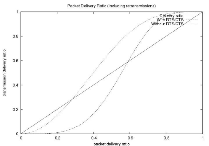

Packet delivery ratio is significantly improved when the RTS/CTS handshake is omitted. This effect can be seen in Figure 6. The average packet delay is reduced if RTS/CTS are omitted. This can be proven using the observation that the expected delay of a transmission assuming all RTS/CTS are successful and ignoring the cost of RTS/CTS is equivalent to the expected delay of the approach that does not use RTS/CTS. Thus, using RTS/CTS, we have to add the cost of the RTS/CTS as well as failed RTS/CTS and the associated increase in backoffs. Figure 7 shows the obtained capacity with and without RTS/CTS for a single hop – clearly, there is a large advantage for the case without RTS/CTS. Similar positive results hold for the delay (not shown).
IV-B Effect on Collisions
A potential drawback of this approach is that the advantages of collision avoidance (RTS and CTS) in reducing collisions and collision cost are lost. We argue that RTS/CTS is only of limited success in eliminating collisions and that the complimentary Carrier Sense Multiple Access (CSMA) is more effective in reducing collisions. Some collisions occur when two senders sense the medium to be idle and transmit concurrently; such collisions cannot be prevented by either approach. However, the vulnerability period to such collisions is low and their effect is not likely to dominate. One advantage that RTS/CTS offer to such collisions is that contention is carried out with small control packets, whereas a full data packet is lost if only CSMA is used.

Collisions occur in a wireless environment if the ratio of the received packet power to the interfering power (other transmissions and noise) fall below a threshold called the capture threshold. Its well known that collision avoidance is not sufficient to prevent collisions: a node that is close enough to the receiver to interfere but not close enough to receive the CTS packet can possibly cause a collision. In Figure 8, we consider a situation where a source (S) is communicating with a receiver (R) in the presence of an interfering node (I). The x-axis shows the distance between the S and R, while the y-axis shows that between I and R. Points on the figure above the capture lines indicate that capture does happen (the interferer is too far) while those below indicate that a collision happens. The capture value represents the capture threshold, while represents the path loss factor (the signal decays with where is the distance from the transmitter). The capture line plots the interferer distance that would cause . Note that this approximate analysis assumes only a single interferer, ignores the effect of noise, and assumes ideal propagation.
Essentially to control collisions all potential interferers (below the capture line on Figure 8) should be blocked. Collision Avoidance (RTS/CTS) can only block interferers in reception range of the receiver (to receive the CTS). Thus, many potential interferers are not blocked with the RTS/CTS mechanism. This is the area under the capture line but above the 250 meter line.
The main mechanism for avoiding collisions in commercial wireless cards is an aggressive Carrier Sense (with low sense threshold). This aggressive threshold is used both to attempt for interferers out of receivers range and for the fact that carrier sense occurs at the sender, but collisions occur at the receiver. For a WaveLAN card [18] with a nominal transmission range of 250 meters, the carrier sense threshold is set such that transmitters in a circle of radius 2.2 times the transmission range around S are forced to stay idle (assuming a path loss factor of 4). Having this aggressive threshold reduces collisions (it does not completely eliminate them), but increases the exposed terminal problem.
CSMA’s effectiveness in blocking interferers is a superset of that of Collision Avoidance: all collisions that can be eliminated by collision avoidance can also be eliminated by CSMA. Furthermore, CSMA is able to prevent many more collisions not preventable by RTS/CTS. Since CSMA is applied at the sender but the interference happens at the receiver, its effectiveness depends on the location of the interferer from the source. More specifically, for carrier sense to occur successfully, the signal power of the interferer at the sender should be above the carrier sense threshold. In the average case (when the interferer to source distance is equal to the receiver to source distance; that is, the interferer location is not biased either closer to the sender or further away from it), CSMA is able to prevent all possible collisions (the average-case line on Figure 8). The worst case for CSMA occurs is when the interferer is on the side of the receiver away from the sender (this is the worst-case line on Figure 8). In this case, the interferer’s distance to the sender is maximized for a given interferer-receiver distance. Even in the worst case, CSMA prevents all collisions catchable by CA – recall that all the cases under the line are prevented for each mechanism. Note that in the worst case, some collisions are not preventable.
Thus, we perceive no benefit for RTS/CTS in reducing collisions. Their only benefit is in reducing the cost of collisions for collisions that occur due to concurrent sensing of an idle channel; in this case, collisions occur on the small RTS/CTS control packets instead of full length data packets. This only works for interferers in range to receive a CTS – this is a relatively small area of possible interferers as seen on the Figure. Moreover, in the case of multiple interferers, their combined interference power may cause a collision. This helps CSMA and hurts CA: CA requires that each of the intereferers be in reception range, while CSMA naturally takes their effect in since carrier sense measures their combined effect. Thus, given the dramatic degradation CA causes on packet delivery ratio in the presence of fading and the small benefit it provides to collisions it is beneficial to eliminate them.
We note that this conclusion is only dependent on the carrier sense threshold. If the path loss component is different, or if the send power is different, this affects both the carrier sense and the collision avoidance. Furthermore, if the capture threshold is different, this has the same effect on both CSMA and CA (the slope of the capture line changes, but not the other lines).
V Backoff Implications – Inefficiency and Unfairness
The second major implication from the basic MAC analysis in Section III concerns the backoff mechanism. The backoff mechanism in contention based MAC protocols (such as 802.11 DCF mode used for MANETs) is intended to regulate the offered load to the shared medium. The underlying assumption is that all packet losses are due to collisions. While this assumption is true in wired shared media where errors are exceptionally rare, it is not true in wireless environments. As a result of losses due to fading, the backoff timer is increased. This leads to two important side effects: (1) Inefficiency in using the medium: backoffs occur even without collisions, leading to nodes backing off excessively causing unnecessary channel idle time; and (2) unfairness: because the expected backoff period increases with the of transmission losses, links that experience losses have a larger average backoff than those that do. IEEE 802.11 is known to be susceptible to short-term transient unfairness even under idealized propagation assumptions [19]. Under fading we show that steady-state unfairness can occur.
The inefficiency issue was already alluded to in the discussion of the delay and effective throughput. Backoff increasingly contributes to the delay as the transmission delivery ratio drops: as a larger number of retries is needed, we have the multiplicative effect of a larger number of backoff periods and longer average backoffs. The problem occurs due to the implicit assumption that losses are due to contention. In the presence of fading, this is often not the case causing inappropriate backoff. Finer discrimination between contention losses (collisions) and transmission losses (fading) are needed.
The unfairness problem occurs due to the imbalance in backoff durations. On average, links with lower transmission success ratios will have a higher backoff period (Figure 4). As a result, competition for the link is no longer fair – links with higher transmission delivery ratio have a higher probability of capturing the link. IEEE 802.11 already suffers from short term unfairness [19]. However, the unfairness problem identified here is sustained. Addressing this problem also requires backoff algorithms that can discriminate between collisions and transmission losses.

To illustrate this problem, we simulate two single hop connections whose sources are in range with each other, but whose receivers are not (to isolate the effect of a single contention point). The distance (and therefore the transmission delivery ratio) of one connection was fixed at 150 meters (Connection 1) and the other varied (Connection 2). Each connection generates CBR traffic at a rate that would use all the available bandwidth if there is no contention. Figure 9 shows the raw throughput obtained by the two connections with and without RTS/CTS. The first observation is that the no RTS/CTS version is able to obtain higher throughput even in the presence of contention. The unfairness problem can be seen on the diagram as the first connection gets an increasingly higher portion of the available bandwidth at the expense of the weaker connection.


Its difficult to assess the degree of unfairness since the expected throughput of the hop goes down with the increased hop delay as the connection becomes weaker. To normalize this effect, we use a metric of the percentage of delivered packets as a ratio of the maximum deliverable packets on the connection if no interference was present. In a fair implementation, the two connections would be able to get an equivalent percentage of their maximum throughput. Figures 10 and 11 illustrate the problem for 500 byte and 1500 byte packets respectively. Clearly, the strong connection dominates for both scenarios. When the two distances are equal, the connections share the bandwidth almost equally since the backoffs are not biased in favor of either connection. The unfairness problem is clear as the connection using the strong link quickly dominates the weaker one. This is true for both packet sizes studied and with and without RTS/CTS.

To verify that the unfairness is due to backoff, we disabled backoff in the above scenario since the vast majority of losses were due to fading. In this case, the two connections were able to get fair access to the medium across all distances (Figure 12). This naive algorithm assumes that all losses are due to fading. Clearly, this is not a feasible solution, but it highlights the importance for discrimination between fading and contention losses. For example, possible discriminators such as channel utilization as a measure of contention or the use of physical level detection of collisions at the receiver with feedback to the sender are likely to provide effective discriminators for controlling the MAC backoff algorithm. This is a topic of future work.
VI Effects on Upper Layers
A number of problems due to fading have been encountered in real testbeds and several solutions have been developed. The most heavily studied problem is the issue of link quality and exposing that to the routing protocol to enable it to evaluate path quality [2, 10]. Moreover, the problem of discovering low quality hops that may become visible due to fading is well known [20, 21]. The problem occurs if the protocol attempts to discover only high quality links – lower quality ones are still occasionally visible to route discovery. One of the proposed solutions is to use MAC filtering to assess the quality of the link before accepting it [20, 21, 22, 23]; this approach improves performance but does not eliminate the problem. We were able to reproduce these problems in our simulations. In this section, we outline additional problems and interactions that arise at the upper protocol layers due to fading. We are pursuing solutions to several of these problems.
VI-A Link and Route Qualities
Exposing link quality to the routing protocol is an important step towards effective evaluation of route qualities. However, we believe that current link quality metrics and their combination into a route costs are not representative of actual behavior. Packet delivery ratio based metrics such as ETX appear to perform better than delay metrics [5, 6]. The route quality is then obtained by adding up the costs of the individual links. However, both link delay and throughput are not linear functions of packet delivery. Simply adding the individual links does not provide an accurate estimate of the delay or expected throughput of the connection.
A more subtle effect occurs at the connection level as well. Due to the unfairness problem, the problem of self-contention among hops of a single connection exhibits markedly different performance when fading is considered. Specifically, under idealized assumptions, there is a bias towards hops closer to the source since these hops supply packets. Thus, later hops cannot be unfair against earlier hops – the best they can hope for is to match them [24]. When fading is considered, the effect of this problem is much more pronounced. More specifically, because a better quality link can dominate the available bandwidth when contending with a lower quality one, the following effect is observed. If a strong connection precedes a weaker one in a multi-hop chain, the strong connection will dominate the weaker one. Thus, packets would be sent to the source of the weaker connection, and get dropped there because it is unable to get a share of the bandwidth to send the packets it received.
If the weaker link comes first, it has a regulating effect on the stronger one – the stronger link is limited in terms of supply packets to what the weaker link can provide it. Thus, the quality of the route is not simply the sum of the qualities of the links – the order of the links has to be considered as well. Alternative, sophisticated packet scheduling techniques can be used to bypass this problem. We believe that addressing the root problem of MAC level unfairness will provide a better solution.

The effect of the link order on chain performance can be seen in Figure 13. In this experiment, the throughput of a two hop connection is tracked. The figure shows 4 situations depending on the quality of the two links. Most interesting is the performance of the middle scenarios. A connection with a weak link followed by a strong one performance much better than a connection with the strong link first. In fact, when the strong link comes first, the throughput is worse than a connection with two weak links (the fourth scenario). Our future research regarding this problem targets coming up with generalized route quality estimates based on link qualities and order.
VI-B Effect of Spurious Route Errors
The dual of discovering unwanted low quality hops is mistakenly thinking that good quality ones are no longer there. Some routing protocols such as DSR [25] assume that a failure to send a packet is due to mobility. Again, this is due to idealized propagation assumptions causing packet losses to be almost always due to mobility. However, packet failures due to repeated collisions have been shown to cause route errors under heavy loads as well [24]. Route errors can have a major effect on performance – leading to expensive route searches and connection interruption while route discovery is accomplished.
Under fading, even in good quality links occasional packet failures do arise. For example, even when the transmission delivery ratio is 90%, there is approximately a 2% chance of a packet failure with 4 retries (as would happen with no RTS/CTS). This would lead to route error getting generated every 50 packets; the effect is even worse when one considers a multi-hop connection – each data packet has a chance of causing a route error at every hop.
The Link Quality Source Routing (LQSR) protocol provides a framework for managing this and similar problems [5]. LQSR constantly monitors path quality by providing feedback to the sender potentially with every packet delivered. While LQSR still generates the Route Error Packet when delivery failure occurs, it does not interpret such a packet as a loss of route at the source – simply, the source penalizes the link (increasing its cost estimate).
Such approaches are needed to filter out transient losses due to fading from real loss of route. However, a large amount of overhead can be generated due to these route error packets. We have developed an approach for locally discriminating between fading losses and loss of connection due to mobility. Essentially, an exponential average of the delivery ratio along an active link is tracked. When packet drops occur, they generate route errors only if the stable estimate of the link quality is low (indicating possibility of disconnection).
VI-C Effect on MAC broadcasts and Route Discovery

Fading has especially high impact on broadcast operations. Unlike unicast packets, MAC level broadcast is not acknowledged – if a broadcast is loss, the loss is undetected and no retransmissions occur. As a result, broadcast transmissions are only delivered at the link level transmission ratio (see Figure 3), making them especially vulnerable to fading. This has important implications on all protocols that use MAC broadcast such as flooding and group communication operations.
Figure 14 shows the effect of this problem on flooding coverage as the network density increases. In this scenario, a number of nodes are deployed randomly in a 1000x1000 meter area; the number of nodes is varied to increase the density. We simulated the effect of fading using probabilistic packet drop to have control on the loss rate. Clearly, the coverage of flooding suffers as the quality of the links drops. This is especially true for sparse networks (and for sparse areas of networks). Moreover, since many optimized Network-Wide Broadcast operations reduce the redundancy in flooding, they end up becoming more vulnerable to fading losses. We characterize this problem and investigate solutions to it in another paper submitted to MobiHoc.
Because of fading packets may fail multiple consecutive retransmissions and be dropped because the retransmission limit is reached. Many routing protocols use MAC level transmission failure as an indicator that the link is no longer available (due to mobility). It is important to have more effective discrimination between packet losses due to fading and those due to mobility.
VII Conclusions
In this paper, we presented the result of a bottom-up investigation of the effect of fading on MANET protocol performance. We first did an analysis of the effect of fading on the MAC layer and showed that packet delivery ratio, packet delay and effective throughput all suffer as a result of fading.
Based on this analysis, we made the case the Collision Avoidance (the RTS/CTS mechanism) is harmful for performance. This case has two sides: under fading, it become significantly harder to deliver packets if 4 successive transmissions must be delivered correctly (RTS/CTS/DATA/ACK) vs. only 2 transmissions if RTS/CTS is not used. In addition, we showed that RTS/CTS has minor benefit in preventing collisions. More specifically, with aggressive carrier sense (as is commonly used in commercial radios), CSMA can prevent all collisions that are also preventable by CA (and in fact, considerably more). The benefit of RTS/CTS is then isolated to making the cost of contention for situations where an interferer is in range with either the sender or the receiver less (due to contention using the smaller RTS packets). Overall, we believe that the large benefit in performance due to eliminating RTS/CTS is not recuperated by the small benefit to the cost of collisions for a subset of the collisions.
Another primary contribution of this paper is to identify an unfairness problem that arises due to fading. More specifically, the MAC layer backoff algorithm presumes that all losses are due to contention. Thus, losses that occur due to fading increase the backoff even when no contention exists. Thus, weaker links are at a disadvantage to stronger links because they end up backing-off more frequently. We showed that this problem can be severe even when the difference in the quality between the links is minor. In the long term, we believe that the root of this problem must be attacked: the backoff algorithm should be able to discriminate between contention and transmission losses. We are investigating techniques to estimate the contention to avoid the inefficiency and unfairness problems that arise due to it. In addition, we outlined the effect of fading on broadcast and multicast operations.
We also presented an overview of additional problems that arise at the upper layers. Some of these problems are known, but the solutions to them are ad hoc in nature and not systemic (for example, the problem of discovering low quality links; also the related problem of dropping good quality ones when a packet fails). One of the problems we outlined is an artifact of the unfairness problem at the MAC layer. As a result of this problem, path quality is sensitive to the order of hops in a multi-hop connection. More specifically, if a strong link is closer to the source than a weaker one, it ends up dominating it due to the unfairness problem: packets would constantly be delivered to the source of the weaker hop only to be dropped there. However, if the weaker link comes first, the stronger link cannot dominate because its packet supply comes from the weaker link. There is a need for a generalized approach for estimating link quality that takes such behavior into consideration.
The fading model we use has several limitations. It treats links symmetrically and assumes that losses are independent; both these assumptions are not valid in real testbeds. Nevertheless, we believe that the problems that are isolated are real but the magnitude of their effect may be different when a more accurate model is used. Moreover, we did not consider the effect of multi-rate MAC protocols [13, 26]. Upgrading the propagation model to better reflect wireless propagation and generalizing our analysis is also a topic of future work.
References
- [1] Theodore S. Rappaport, Wireless Communications : Principles and Practice, Prentice Hall, 2002.
- [2] D. De Couto, D. Aguayo, B. Chambers, and R. Morris, “Performance of multihop wireless networks: shortest path is not enough,” ACM SIGCOMM Computer Communication Review, vol. 33, pp. 83–88, Jan. 2003.
- [3] D. De Couto, D. Aguayo, J. Bicket, and R. Morris, “A high-throughput path metric for multi-hop wireless routing,” in Proceedings of the 9th annual international conference on Mobile computing and networking (MobiCom), Sept. 2003.
- [4] A. Adya, P. Bahl, J. Padhye, A. Wolman, and L. Zhou, “A multi-radio unification protocol for IEEE 802.11 wireless networks,” in Proc. BroadNets 2004, 2004.
- [5] Richard Draves, Jitendra Padhye, and Brian Zill, “Comparison of routing metrics for static multi-hop wireless networks,” in Proc. of SIGCOMM 2004, Aug. 2004.
- [6] A. Woo, T. Tong, and D. Culler, “Taming the underlying challengines of reliable routing in sensor networks,” in Proc. of Sensys 2003, 2003.
- [7] Bernard Sklar, “Rayleigh fading channels in mobile digital communication systems part 1: Characterization,” in IEEE Communication Magazine, July 1997.
- [8] UC Berkeley/LNBL/ISI, “The ns-2 network simulator with the cmu mobility extensions,” 2002, http://www.isi.edu/nsnam/ns/.
- [9] Scalable Networks Inc., “The qualnet 3.6 simulator,” 2004, http://www.scalable-networks.com.
- [10] Daniel Aguayo, John Bicket, Sanjit Biswas, Glenn Judd, and Robert Morris, “Link-level measurements from an 802.11b mesh network,” in Proc. of SIGCOMM 2004, Aug. 2004.
- [11] M. Marina and S. Das, “Routing performance in the presence of unidirectional links in multihop wirelss networks,” in Proceedings of the 3rd ACM Interational Symposium on Mobile Ad Hoc Networking and Computing, (MobiHoc 2002), June 2002.
- [12] IEEE 802.11 – The Working Group for Wireless LANs, “Ieee 802.11 standard, 1999 edition,” 1999, Including IEEE 802.11a and IEEE 802.11b Extension. Available for download from http://www.ieee802.org/11/index.html.
- [13] B.Sadeghi, V.Kanodia, A.Sabharwal, and E.Knightly, “Opportunistic media access for multirate ad hoc networks,” in Mobicom 2002, 2002.
- [14] T. Pagtzis, P. Kirstein, and S. Hailes, “Operational and fairness issues with connection-less traffic over IEEE802.11b,” in Proc. ICC’01, 2001, http://www.cs.ucl.ac.uk/staff/t.pagtzis/papers/papers/ICC01opIssues802.%11b.pdf.
- [15] The Bluetooth Special Interest Group, “The bluetooth specification,” Feb. 2001, Available from http://www.bluetooth.com/.
- [16] IEEE 802.15 WPAN Task Group 4, “IEEE 802.15 Standard,” 2004, http://www.ieee802.org/15/pub/TG4.html.
- [17] A. Woo and D. Culler, “A transmission control scheme for media access in sensor networks,” in Proceedings of the Seventh Annual International Conference on Mobile Computing and Networking, July 2001.
- [18] ,” WaveLAN/PCMCIA Card User’s Guide – Lucent Technologies.
- [19] N. Vaidya, P. Bahl, and S. Gupta, “Distributed fair scheduling in a wireless lan,” in Proceedings of Mobicom 2000, Aug. 2000.
- [20] K-W. Chin, J. Judge, A. Williams, and R. Kermode, “Implementation experience with MANET routing protocols,” ACM SIGCOMM Computer Communication Review, vol. 32, pp. 49–59, Nov. 2002.
- [21] D. Maltz, J. Broch, and D. Johnson, “Quantitative lessons from a full-scale multi-hop wireless ad hoc network testbed,” in Proc. of the IEEE Wireless Communication Networking Conference (WCNC), Sept. 2000.
- [22] R. Dube, C. Rais, K.-Y. Wang, and S. Tripathi, “Signal Stability based Adaptive Routing (SSA) for Ad-Hoc Mobile Networks,” IEEE Personal Communication, pp. 36–45, Feb. 1997.
- [23] T. Goff, N. Abu-Ghazaleh, D. Phatak, and R. Kahvecioglu, “Preemptive maintenance routing in ad hoc networks,” in Proceedings of the 2001 ACM Mobicom Conference, July 2001, pp. 43–52.
- [24] S. Xu and T.s Saadawi, “Revealing the problems with 802.11 medium access control protocol in multi-hop wireless ad hoc networks,” Computer Networks, vol. 38, no. 4, pp. 531–548, Mar. 2002.
- [25] D. Johnson, D. Maltz, Y-C. Hu, and J. Jetcheva, “The dynamic source routing protocol for mobile ad hoc networks,” Internet Draft, Internet Engineering Task Force, Mar. 2001, http://www.ietf.org/internet-drafts/draft-ietf-manet-dsr-05.txt.
- [26] Yongho Seok, Jaewoo Park, and Yanghee Choi, “Multi-rate aware routing protocol for mobile ad hoc networks,” in Proc. 57th IEEE Vehicular Technology Conference, 2003, pp. 1749–1752, vol. 3.