Enhancement of Josephson quasiparticle current…
Enhancement of Josephson quasiparticle current in coupled superconducting single-electron transistors
Abstract
The Josephson quasiparticle (JQP) cycle in a voltage-biased superconducting single-electron transistor (SSET) combines coherent Cooper pair tunneling with incoherent quasiparticle decay. We have measured the influence of current flow through an independently-biased SSET on the JQP cycle when the two SSET’s have a strong mutual capacitive coupling. We find, among other effects, that the JQP current in one SSET is enhanced by the presence of a quasiparticle current in the other SSET. A simplified model of the coupled-SSET system is presented which reproduces the enhancement effect.
PACS numbers: 73.23.Hk, 74.50.+r, 85.30.Wx, 85.25.Na
1 INTRODUCTION
Superconducting single-electron transistors (SSET’s) are small islands of superconducting material isolated from an external circuit by tunnel barriers (Josephson junctions). The normal tunnel barrier resistances (6.5 k) are sufficient to constrain the excess charge on the island to integer multiples of . At equilibrium, adding an electron to an electrically neutral island costs a charging energy , where is the island’s total capacitance. This ”Coulomb blockade” may be lifted by applying a gate voltage to the SSET, or it may be surmounted by applying a sufficient source-drain bias voltage.
At zero voltage bias, a supercurrent of Cooper pairs may flow coherently through the SSET, while for a large voltage bias (, where is the superconducting gap), the current is dominated by successive charging and discharging of the island by quasiparticles. Within a range of moderate bias (), current flows via a hybrid transport mechanism termed the ”Josephson quasiparticle cycle” (JQP)1,2. In each turn of the cycle, a Cooper pair (CP) resonantly tunnels into the SSET through one junction, accompanied by a quasiparticle (QP) tunneling event through the other junction, leaving one extra QP on the island. This extra QP then also tunnels through the second junction, and the cycle starts anew.
In this paper we show some intriguing measurements of the JQP current flowing through a SSET that is strongly coupled to a nearby, independently voltage-biased SSET. The two islands are coupled by a large capacitance supplied by an overlap capacitor instead of a tunnel junction, so there is no Josephson coupling between the islands themselves. The charging energy associated with this mutual capacitance is given by:
| (1) |
where is the total capacitance of island (including ). The strong capacitive coupling ensures that the charge of one island influences the QP and CP tunneling rates for the other island, since .
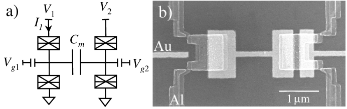
The islands were formed by the standard procedure of double angle evaporation of Al, with an oxidation step to form AlOx tunnel barriers between each island and its leads (Fig. 1(b)). The gate electrodes and the central metal strip coupling the two islands were created in an underlying Au layer, with an intermediate insulation layer of SiO (32 nm). From normal-state measurements [4], the junction capacitances were determined to be 0.3 fF, while 0.6 fF. The series resistances of the SSET’s were 7 and 13 M, so the Josephson energies of the tunnel junctions are expected to be very small ( 0.1 eV) compared to the charging energy ( 80 eV) and 40 eV.
Measurements of the device were carried out at low electron temperature (27 mK) in a helium dilution refrigerator. The source-drain voltage biases for the two SSET’s () were applied asymmetrically, with one lead from each SSET tied to ground (Fig. 1(a)).
2 NORMAL STATE MEASUREMENTS
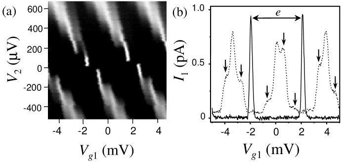
Before discussing the JQP experiments, we will discuss some relevant properties of the system in the normal state. After applying a 1 T magnetic field to suppress superconductivity, we measured low bias ( = 20 V) Coulomb oscillations in the left SET for various values of . The results are plotted in Figure 2. We observe that when is sufficient to allow single-electron transport through the right SET, the Coulomb peaks spread, develop small sidepeaks, and diminish in amplitude. These measurements agree with our simulations based on the orthodox theory of single-electron tunneling [3].
The sidepeaks are due to the discrete charging of the right SET. The presence of an extra electron induces a charge of 0.25 on the left SET via ; this shifts the Coulomb peak to a different , resulting in the extra peaks marked by arrows in Fig. 2(b). Each peak can thus be indexed by the charge of the right SET ().
Note that the peaks (and sidepeaks) are not strictly -periodic ( 4 mV), since has a cross-capacitance to the right SET. This effect can be cancelled by countersweeping in proportion to .
3 JQP ENHANCEMENT
During our experiments in the superconducting state, the left SSET was biased to be in the JQP regime. When was grounded, sweeping the gate voltage produced a series of small peaks (0.5 pA) periodic with gate charge of . Typically one expects two peaks per period, corresponding to CP resonances in either junction. In our device, the second JQP peak was barely observable, suggesting that the tunnel barrier resistances (and thus the Josephson energies) were very dissimilar.
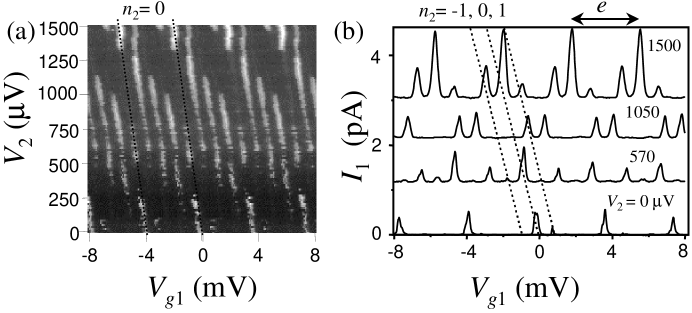
The effects of biasing the right SSET are shown in Figure 3, where is plotted as a function of for various values of . was counterswept to cancel the cross-capacitance from to the right SSET, fixing the induced charge of the right SSET in each gate sweep. Capacitive effects due to the changing asymmetric bias voltage were not cancelled, however, resulting in a slight leftward shift of the peaks for increasing .
For small , only one (or two) peaks are visible per period. Beginning at a bias of about 470 V, up to four distinct peaks are seen per period. This bias is too small to allow successive QP tunneling, so the appearance of extra peaks may indicate a parallel JQP cycle in the right SSET. As an example of the complex behavior seen in this regime, at = 570 V (Fig. 3(b)), peaks corresponding to an even are all larger than those with odd . The four-peak structure continues up to 800 V (). At higher biases the peaks disappear one by one, then re-emerge with about three times their low-bias amplitude. The peak heights continue to increase for even higher ; no saturation in the peak height was seen in similar experiments where was swept up to 5 mV. This enhancement of the JQP peaks is in stark contrast to the normal state measurements, where the peak height only diminished with increasing (Fig. 2(b)).
4 MODEL AND DISCUSSION
Although we cannot presently account for each peak’s behavior, it is clear from the sharp sidepeaks that each SSET is sensitive to the other’s charge. In this section we introduce a possible mechanism for the peak enhancement in the left SSET above , where the current through the right SSET is carried predominantly by quasiparticles.
Part of the explanation for the enhancement must take into account events involving the simultaneous transfer of charge in both SSET’s. The two processes of interest in our model are depicted in Figure 4, for the case when a CP can resonantly tunnel into the left SSET only if an extra QP is resident in the right SSET. Using the notation (,) to refer to the combined charge state having and extra electrons on the two respective islands, the states (0,1) and (2,1) are resonant, but (0,0) and (2,0) are not.
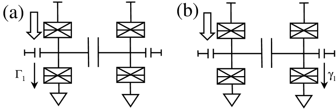
In the usual JQP process (Fig. 4(a)), the CP tunnels into the left SSET while a QP tunnels off with rate , so that (2,1) decays to (1,1). The cycle is completed when (1,1) decays to (0,1). In coupled SSET’s, the tunneling of the CP can also be coincident with a QP decay from the SSET, so that (2,1) decays to (2,0) with rate , leaving an extra CP in the left SSET. This CP then spontaneously decays via two QP decays to ground, and the cycle can restart after a QP tunnels into the right SSET and brings the left SSET back into resonance.
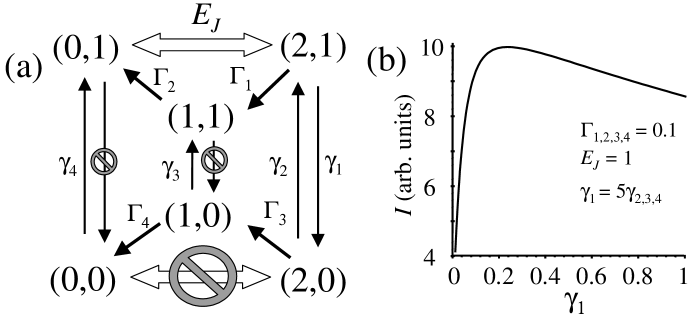
Just as the charge of the right SSET affects the CP resonances in the left SSET, the charge of the left SSET affects the QP tunneling rates of the right SSET. The voltage across a junction must exceed for a QP to tunnel across it (ignoring the small subgap conductance). Due to the influence of the strong mutual coupling, some of these QP tunneling events can be blocked depending on the charge of the other island. Our model assumes that the right SSET can only undergo QP decay to ground when the left SSET has a charge (ie. if a CP is resident), but a QP can tunnel into the right SSET for . The allowed (and disallowed) transitions are summarized in Figure 5(a). Transitions in the left (right) SSET are denoted by ().
Since , one can show that the (allowed) QP rate through each junction, regardless of the charge state under consideration, is well-approximated (within a factor of 2) by , where is the voltage across the junction, and is the normal-state tunneling resistance. The rates all occur through the lower left junction, so we set: . Likewise, the rates (except ) all occur through the upper right junction, so . The rates are fixed, since is fixed, but the rates will increase along with .
We will assume that , corresponding to asymmetric tunnel barrier resistances for the left SSET (as mentioned in Section 3). This condition means that the JQP current is bottlenecked by slow QP decay. We will also assume that , corresponding to asymmetric resistances for the right SSET. The asymmetries are necessary to produce peak enhancement in our model.
Based on these assumptions, we have calculated the peak JQP current as a function of (Fig. 5(b)), using a density matrix formulation[5]. The plot shows a clear enhancement of for . The enhancement is even more pronounced if the asymmetry between and is stronger.
The enhancement can be understood by considering the effect of on the charge state populations. The current can be shown to be equal to:
| (2) |
where is the population of the (,) charge state, corresponding to the appropriate diagonal element of the density matrix. The current is directly related to the probability of finding a CP in the left SSET. We find that increases dramatically with , while is only slightly suppressed. In other words, the left SSET becomes more likely to contain a CP when the right SSET carries a current of QP’s. Due to the coherent nature of CP tunneling, one cannot be sure that the CP is on the island until a QP is emitted. In the usual JQP process this QP tunnels off the island itself with rate (Fig. 4(a)), immediately destroying the CP. The larger this rate is, the less likely that the SSET contains an extra CP since the lifetime of the state is shorter and the resonance is weakened. In the coupled-SSET system, however, the presence of the CP can also be detected by the emission of a QP with rate from the other SSET (Fig. 4(b)). The larger this rate is (up to a point), the more likely that the left SSET contains an extra CP, since this tunneling event does not change the charge of the left SSET.
In conclusion, we have observed a striking modification of the JQP current flowing through one SSET as a result of its strong Coulomb interaction with another SSET. We interpret these results as being a quantum measurement effect, since the tunneling rates for each SSET are highly sensitive to the other SSET’s charge, and thus one SSET can detect the presence or absence of a Cooper pair in the other SSET.
The authors gratefully acknowledge the input of Caspar van der Wal, K. K. Likharev, and M. Wegewijs. This research was supported by CHARGE, Esprit Project No. 22953, and by Stichting voor Fundamenteel Onderzoek der Materie (FOM).
References
- [1] T. A. Fulton, P. L. Gammel, D. J. Bishop, L. N. Dunkleburger, and G. J. Dolan, Phys. Rev. Lett. 63 1307 (1989).
- [2] Y. Nakamura, C. D. Chen, and J. S. Tsai, Phys. Rev. B 53 8234 (1996).
- [3] See, for example, Single Charge Tunneling, edited by H. Grabert and M. H. Devoret (Plenum, New York, 1992).
- [4] C. P. Heij, D. C. Dixon, P. Hadley, and J. E. Mooij, Appl. Phys. Lett. 74 1042 (1999).
- [5] S. A. Gurvitz, Ya. S. Prager, Phys. Rev. B 53 15932 (1996).