Origin of the Charge-Orbital Stripe Structure in La1-xCaxMnO3 ()
Abstract
We propose the origin of the charge-ordered stripe structure with the orbital ordering observed experimentally in La1-xCaxMnO3 (), in which the long-range Coulomb interaction plays an essential role. We study a Hubbard model with doubly-degenerate orbitals, and treat the on-site Coulomb interaction () and the nearest-neighbor one () with the Hartree-Fock approximation. Both the charge and orbital ordering structures observed in experiments are reproduced in a wide region of the - phase diagram determined by the present study. The stability of the orbital ordering is also confirmed by the perturbation theory.
PACS numbers: 71.20.Be, 71.10.-w, 71.10.Fd
In some perovskite-type hole-doped manganese oxides MnO3 ( : rare earth elements, : alkaline earth elements), the colossal magnetoresistance effect has been the subject of intense studies. Recently, characteristic charge ordering phenomena in these materials have also attracted a growing interest. Especially, in La1-xCaxMnO3 for and , it has been reported that the charge-orbital stripe (COS) structure occurs in some periodicities which correspond to the commensurate concentrations [1, 2, 3, 4, 5, 6].
Concerning the pure LaMnO3 system (), the antiferromagnetic (AF) insulating phase appears [7], where the orbital ordering accompanied with the Jahn-Teller (JT) distortion coexists because of the JT active ion Mn+3 [8, 9]. In the same way, it is suggested that the JT effect is also the origin of the stripe structure in the systems with finite carrier concentrations such as and [5, 10]. According to this scenario, however, a considerably strong JT effect is necessary to realize the insulating COS structure [10]. In this sense, it is insufficient to ascribe the origin of the stripe structure only to the JT effect.
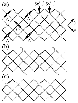
In the present letter, we show that the COS structure observed in the La1-xCaxMnO3 can be explained only by considering the Coulomb interaction between carriers. We study a Hubbard model with doubly degenerated orbitals which correspond to orbitals on Mn ions. By treating the Coulomb interaction with the Hartree-Fock approximation, we investigate the stability of the COS structure observed in experiments for the system (Fig. 1(a)) [1, 2, 11] and the system (Fig. 1(b)) [6, 11], and discuss the another type of the charge ordering found by electron microscopy study reported in Ref. [5] (Fig. 1(c)). We show that the COS structure appears for the realistic strength of on-site and nearest-neighbor Coulomb interactions. In particular, we emphasize that the nearest-neighbor Coulomb interaction is indispensable for the occurrence of the stripe structure with the orbital ordering.
Several authors have studied the effect of the on-site Coulomb interaction on the orbital ordering in manganese oxides previously [12, 13, 14, 15]. Especially, in the system, it was shown that the orbital ordering is stabilized by the on-site Coulomb interaction [14]. However, the effect of the long-range Coulomb interaction have not been studied enough.
The charge ordering in La1-xCaxMnO3 systems is the ordering of Mn ions with different valences: Mn+3 and Mn+4. Three electrons in orbitals construct the localized spin. The strong Hund coupling works between the localized spin and the spin of the itinerant electron. The difference of valences between Mn+3 and Mn+4 corresponds to whether the Mn ion has an electron or not.
In the COS phase observed in both and systems, the COS structures are formed in all the - planes, and they are stacked along the -axis without misfitting. Thus, for simplicity, we investigate the charge configuration in the two-dimensional system which corresponds to the - plane. The charge ordering is also observed in layered-type manganese oxides [16].
The Hamiltonian which we consider is expressed as follows;
| (1) | |||||
| (2) |
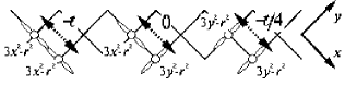
where denotes a number operator on the site . Indices and correspond to two orbitals of : and symbolized by and , respectively. In the first term of the Hamiltonian, is the hopping integral between the orbital on the site and on . We define hopping integrals between nearest-neighbor sites as follows;
| (5) | |||||
| (6) | |||||
| (9) |
where and denote unit vectors of and directions, respectively (Fig. 2). We introduce values of and as and [17]. Then, the band width of the free system () is equal to . Hereafter we take as the energy unit.
In the insulating phase, the screening effect of the Coulomb interaction is expected to be suppressed. Thus, not only the on-site Coulomb interaction but also the nearest-neighbor one becomes important. We assume for simplicity that the nearest-neighbor Coulomb interaction is not depend on orbitals.
The Hamiltonian (1) is based on the double exchange model [18]. For the strong Hund coupling (), it is expected that the spin of the electron in the band is fixed to be parallel to the local spin at . Thus we neglect the spin degeneracy for both the ferromagnetic and the paramagnetic states. In other words, we consider the spinless fermion system [19]. The present model can be interpreted as a single-band Hubbard model with spin-dependent hopping integrals provided the orbital degree of freedom is expressed as the pseudo-spin. Below, we show that the above simplified model can reproduce the COS structure observed in manganese oxides.
The carrier concentration is given by
| (10) |
where denotes the number of sites. In this letter, we treat two cases with carrier concentrations and which correspond to systems with and in La1-xCaxMnO3, respectively. Hereafter, we apply the Hartree-Fock approximation to the two terms with Coulomb interactions and in the Hamiltonian (1), and determine - phase diagrams.
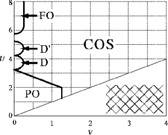
First we show the result for the case which corresponds to the La1/2Ca1/2MnO3 system. In the phase diagram Fig. 3, we see the COS phase, whose structure is schematically displayed in Fig. 1(a) or the inset of Fig. 3, spreads out in the wide region. The COS phase is realized generally in many compounds of MnO3 (see Fig. 1(a)), and it is called the CE type [7] except for the spin configuration.
There is the ferro-orbital (FO) phase around for , where the orbital ordering is realized but the charge ordering does not occur; and for all sites. We comment that this FO phase, which appears only in the region , may be the artifact of the mean-field approximation. In reality, in a single-band Hubbard model, ferromagnetism is hardly realized beyond the mean-field approximation [20]. On the other hand, the COS phase is realized for , which means the validity of the COS phase beyond the mean-field approximation.
For smaller , the para-orbital (PO) phase is realized, where neither charge ordering nor orbital ordering exist : for all sites. For the limited region of and the small , D and D’ phases exist. We do not mention their structures here. Note that FO and PO phases are metallic.
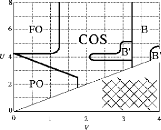
Let us turn to the case with the carrier concentration . In the recent neutron diffraction experiment for La1/3Ca2/3MnO3 [6], the stripe structure corresponding Fig. 1(b) is realized undoubtedly. In the present result, the same COS structure is reproduced in the fairly wide region of the - diagram as shown in Fig. 4. We emphasize that the region of the COS phase includes the realistic values of and , and it is expected to spread further if we include the long-range Coulomb interaction beyond the nearest-neighbor one.
For , another types of the charge ordering denoted by B and B’ occur. However we do not mention these structures since they appear only for unrealistically larger values of . Similarly to the case, there is the PO phase with neither charge nor orbital orderings for smaller values of in the case. The FO phase also exists for and . In the case, however, the regions for these phases spread out more widely than those for the case.
The mechanism of the COS structure for displayed in Fig. 1(a) can be understood by the perturbation treatment as follows. We assume and set for simplicity in eq. (9). For large values of and , it is natural that carriers order alternatively on lattice sites and each orbital on a site is singly occupied. In the configuration shown in Fig. 1(a), the ground-state energy is given by . If the -orbital is occupied on the O-site (Fig. 1(a)) instead of , the ground state energy is raised by , since the energy-gain through the exchange processes with the -orbital electrons at (A,A’)-sites are reduced. For the orbital ordering of the case, a similar argument also holds in the order of provided the charge ordering is constructed. Thus we understand the reason why the long-range Coulomb interaction stabilizes the COS structure with the orbital ordering.
Let us discuss another pattern of the COS structure shown in Fig. 1(c), which is realized on the surface of the sample in La1/3Ca2/3CuO3 according to Ref. [5]. This paired COS does not appear in the present phase diagram (Fig. 4) in which the JT distortion is neglected. Concerning the JT distortion, each non-paired Mn3+ stripe causes significant lattice distortion in its immediate neighborhood and the overall strain energy will be lowered by forming periodic array of pairs on Mn3+ stripes separated by undistorted regions of Mn4+ ions [5]. We note that the JT distortion is stronger than the bulk one, since the elastic constant on the surface is smaller.
In order to estimate the strength of the JT distortion energy enough to construct the paired stripe structure, we consider the following JT Hamiltonian .
| (11) |
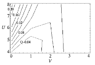
where denotes the sites which correspond to the paired stripe shown in Fig. 1(c); in a pair , sites and are the left and right site of the pair, respectively. In the Hamiltonian (11), denotes the potential energy which corresponds to the electron-lattice coupling related to the linear displacement of the JT distortion [21]. For simplicity, we neglect the mixing term between two orbitals and to realize the configuration in Fig. 1(c). The lattice elastic energy, which is proportional to the square of the displacement, is neglected. For the system added the above Hamiltonian (11), we calculate the energy under the constraint; and for . Figure 5 shows the contour diagram for values of which are needed to realize the paired stripe structure for certain values of (,) with the same ground-state energy of the system without the constraint.
Obviously, in the case of , fairly large values of are needed to realize the paired stripe structure. On the other hand, for the region of the COS phase in Fig. 4, the paired stripe structure can be realized with relatively small values of . This indicates that the nearest-neighbor Coulomb interaction is also important to construct the paired stripe structure. The result suggests the possibility that the paired stripe structure reported in Ref. [5] on the surface is realized owing to the smaller elastic constant on the surface than that in the bulk.
Finally, we explain some experiments on the COS phase and discuss the validity of the long-range Coulomb interaction scenario; in Pr1-xCaxMnO3 systems, it was reported that the charge-ordering transition temperature () is suppressed with external pressure [22]. Under pressure, the transfer integral is expected to become large, and both and decrease. In fact, absolute values of the resistivity are suppressed with increasing pressure [22]. The reason why the charge ordering becomes unstable is expected to be the reduction of and in the phase diagram, Figs. 3 and 4. The present conclusion is qualitatively consistent with the above experimental result. The similar behavior is also reported in layered-type manganese oxides with chemical pressure [23].
On the other hand, recently, the charge-ordering phenomenon was observed in thin films (thicknesses are Å) in Nd0.5Sr0.5MnO3 [24]. It was shown that almost does not change when the thickness of the sample changes, although the JT distortion varies sensitively with the thickness of the sample. This is consistent with the present result because we show that the COS structure can appear without taking account of the JT effect. It is suggested that the JT effect is not so important to the construction of the COS structure observed in manganese oxides with .
We would like to comment on that we treated the spinless system in the present study. In manganese oxides in which the charge-ordered phase is observed, is higher than the AF transition temperature for [3], which will mean that the AF ordering is a phenomenon in the lower energy scale. It is of course expected that the RKKY interaction, which is neglected in the present study, becomes effective to the AF ordering at lower temperatures.
In summary, we have shown that the COS phase appears in a wide region of the - phase diagram for both and cases. We conclude that the COS structure observed in LaxCa1-xMnO3 for and is originated from the Coulomb interaction. It is emphasized that doubly-degenerated orbitals and the nearest-neighbor Coulomb interaction are important to realize the COS structure. According to the present scenario, the COS structure is realized by the long-range Coulomb interaction at first. After that, the JT distortion occurs so that the COS structure is stabilized. In conclusion, the JT distortion is the consequence of the COS structure but not the origin of it.
We are grateful to K. Ueda for valuable comments. One of the author (T.M.) is supported by the Special Postdoctoral Researchers Program from RIKEN. A part of the numerical calculations was performed on the super-computer VPP700E of RIKEN.
REFERENCES
- [1] C.H. Chen and S.-W. Cheong, Phys. Rev. Lett. 76, 4042 (1996).
- [2] P.G. Radaelli et al., Phys. Rev. B 55, 3015 (1997).
- [3] A.P. Ramirez et al., Phys. Rev. Lett. 76, 3188 (1996).
- [4] C.H. Chen, S.-W. Cheong, and H.Y.Hwang, J. Appl. Phys. 81, 4326 (1997).
- [5] S. Mori, C.H. Chen, and S.-W. Cheong, Nature 392, 473 (1998).
- [6] M.T. Fernández-Díaz et al., Phys. Rev. B 59, 1277 (1999).
- [7] E.O. Wollan and W.C. Koehler, Phys. Rev. 100, 545 (1955).
- [8] J.B. Goodenough, Phys. Rev. 100, 564 (1955); J. Kanamori, J. Appl. Phys. Suppl. 31, 14S (1960); G. Matsumoto, J. Phys. Soc. Jpn. 29, 606 (1970).
- [9] According to recent theoretical studies, the orbital ordering for the system is stabilized by the JT distortion [12, 13, 14].
- [10] T. Hotta, Y. Takada, and H. Koizumi, Int. J. Mod. Phys. B12 3437 (1998).
- [11] From results shown in Ref. [2, 6], it is supposed that the orbital ordering accompanied with the charge ordering schematically displayed in Fig. 1(a) and (b) occurs in both and systems.
- [12] T. Mizokawa and A. Fujimori, Phys. Rev. B51, 12880 (1995).
- [13] S. Ishihara, J. Inoue, and S. Maekawa, Physica C263, 130 (1996); Phys. Rev. B55, 8280 (1997).
- [14] W. Koshibae et al., J. Phys. Soc. Jpn. 66, 957 (1997).
- [15] R. Maezono, S. Ishihara, and N. Nagaosa, Phys. Rev. B58, 11583 (1998).
- [16] See e.g. Y. Moritomo et al., Phys. Rev. B51, 3297 (1995).
- [17] S. Ishihara, M. Yamanaka, and N. Nagaosa, Phys. Rev. B56, 686 (1997).
- [18] C. Zener, Phys. Rev. 81, 440 (1951); H. Hasegawa and P.W. Anderson, Phys. Rev. 100, 675 (1955); P.-G. de Gennes, Phys. Rev. 118, 141 (1960).
- [19] J. Zang et al., Phys. Rev. B 53, R8840 (1996).
- [20] See e.g. J. Kanamori, Prog. Theor. Phys. 30, 275 (1963).
- [21] A.J. Millis, Phys. Rev. B 53, 8434 (1996).
- [22] Y. Moritomo et al., Phys. Rev. B55, 7549 (1997).
- [23] Y. Moritomo et al., Phys. Rev. B56, 14879 (1997).
- [24] W. Prellier et al., submitted to APL (cond-mat/9903178).