Anisotropic Transport of Two-Dimensional Holes in High Landau Levels
Abstract
Magnetoresistance data taken along and directions in a GaAs/AlGaAs two-dimensional hole sample with van der Pauw geometry exhibit significant anisotropy at half-integer filling factors. The anisotropy appears to depend on both the density and symmetry of the hole charge distribution.
pacs:
PACS: 73.20.Dx, 73.40.Kp, 73.50.JtKeywords: Quantum Hall Effect, Anisotropy
A remarkable magnetotransport anisotropy at half-integer fillings was recently reported in high-mobility GaAs/AlGaAs two-dimensional electron systems (2DESs) [2, 3]. In particular, at half fillings in the third and higher Landau levels (), the in-plane longitudinal magnetoresistance () in one direction was observed to be much larger than in the perpendicular direction. We present here qualitatively similar anomalies in a high-mobility GaAs/AlGaAs 2D hole system (2DHS). The 2DHS data, however, provide an intriguing twist to this problem as they exhibit the anomaly at fillings as small as .
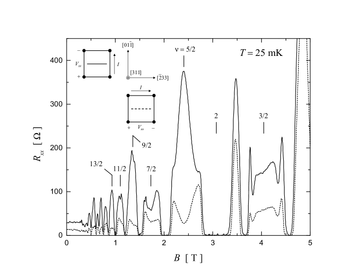
Figure 1 highlights our data which were taken with the magnetic field perpendicular to the 2DHS. The sample is a GaAs quantum well flanked by AlGaAs barriers, grown on a GaAs (311)A substrate, and modulation-doped with Si. The van der Pauw geometry of the sample and the measurement configurations are shown as insets to the main figure. The anisotropy of at half filling is most pronounced: the resistance along the direction (solid trace) exhibits a maximum which is about 15 times larger than the resistance minimum observed along (dashed trace). Note in Fig. 1 that, as decreases, the strength of the anisotropy diminishes in an alternating fashion: larger anisotropies are observed at , , and compared to , , and . This is similar to the case of 2DESs [2, 3].
In Fig. 1, the transport anisotropy persists down to , implying a higher mobility (by a factor of about two) along compared to . This is typical of 2DHSs grown on GaAs (311)A substrates [4]. The origin of this mobility anisotropy can be traced to corrugations, aligned along , which are present at the GaAs/AlGaAs (311)A interface [5]. Such interface morphology anisotropy, however, cannot by itself explain the much larger and alternating transport anisotropy observed at high .
Both Refs. [2] and [3] suggest that the anisotropy observed at half fillings is intrinsic to very high mobility 2DESs and may signal the formation of a new, correlated, striped phase of the 2D electrons. They also conclude that, in the absence of a parallel , such a state forms exclusively in the higher Landau levels (LLs), namely and higher, since they observe the transport anisotropy only at half-fillings . If so, why does the 2DHS exhibit the anisotropy at as small as ? The origin of this difference is not obvious. We propose here three possibilities: (i) The (311)A interface corrugations may help stabilize the anisotropic state in 2DHSs. (ii) It may be related to the nonlinear LL fan diagram for 2D holes and, in particular to the mixing and crossings of the spin-split LLs [6]. The exact sequence and spin-character of the 2DHS LLs, however, depend on the 2D density as well as the shape and symmetry of the confinement potential and the hole wavefunction, so that a quantitative assesment of this hypothesis requires further work. (iii) The larger effective mass of GaAs holes renders the 2DHS effectively more dilute [7]. At a given filling, such diluteness favors crystalline states of the 2D system over the fractional quantum Hall (FQH) liquid states [7, 8]. It is therefore possible that a striped phase is favored in the 2DHS at while in the 2DESs the ground state is a FQH liquid. Such a scenario is consistent with the very recent data in 2DESs [9, 10] which reveal that applying an in-plane -field destroys the FQH state and stabilizes an anisotropic state.
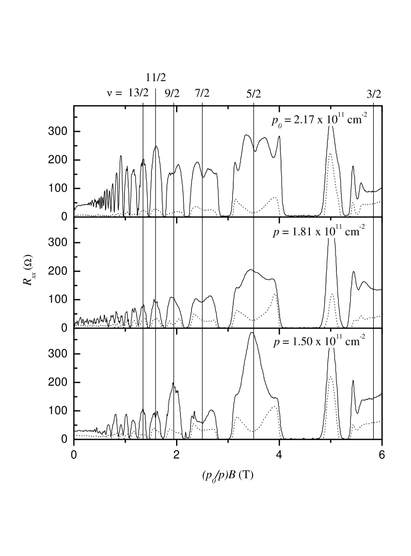
Figure 2 illustrates the evolution with density of for the 2DHS of Fig. 1. The density obtained by cooling the sample in the dark, cm-2 was lowered via successive illumination at low temperature by a red light-emitting diode. At all densities the transport is highly anisotropic at half-integer fillings. At the highest density however, along exhibits a clear minimum along . The minimum is accompanied by a weak feature in the Hall resistance [11], suggestive of a developing FQH state. As the density is lowered, this minimum vanishes and is replaced by a maximum. This evolution with decreasing density has some resemblance to the 2DES data where increasing the in-plane leads to the destruction of the FQH state [9, 10]. It is also consistent with the above interpretation (iii) that diluteness (lower density) favors the anisotropic state over the FQH state.
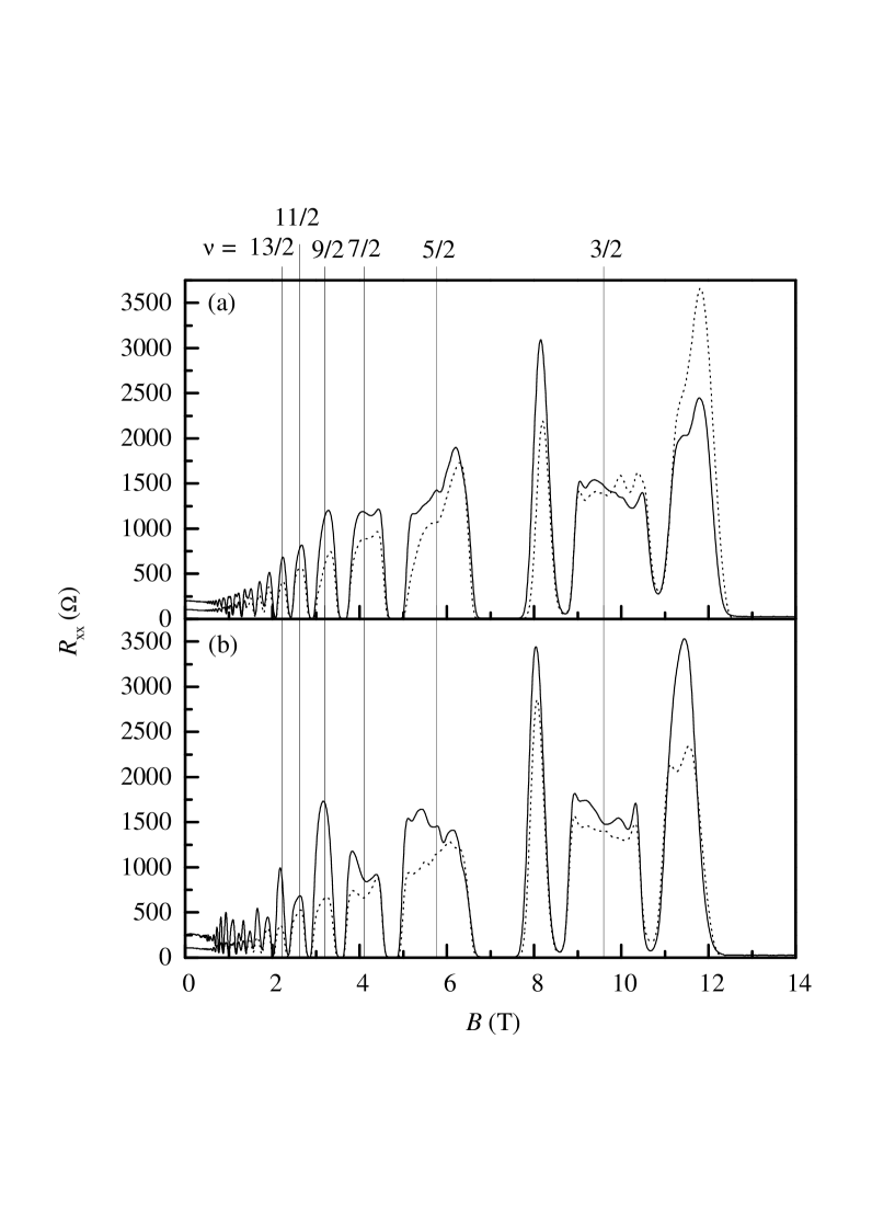
Finally, in Fig. 3 we show data taken on an L-shaped Hall bar sample from a different wafer [12]. The two arms of the Hall bar are aligned along the and directions, and the sample has front and back gates which are used to tune the symmetry of the hole wavefunction while keeping the density fixed [13]. The data overall exhibit much less transport anisotropy, confirming that the van der Pauw geometry exagerates anisotropy because of the non-uniform current distribution [14]. Moreover, only the data of Fig 3b, taken with an asymmetric charge distribution, show significant anisotropy at half-integer fillings for ; note also that the magnitude of the anisotropy alternates with decreasing . The data for the symmetric charge distribution (Fig. 3a), on the other hand, exhibit a smaller size anisotropy which appears to be monotonic with . While we do not understand the origin of these differences, we mention that the LL fan diagrams for the two charge distributions are likely to be different and also the 2DHS becomes more sensitive to interface corrugations when the charge distribution is made asymmetric.
This work was supported by the National Science Foundation.
REFERENCES
- [1] Current address: IBM Research Division, Almaden Research Center, 650 Harry Road, San Jose, CA 95120.
- [2] M. P. Lilly et al., Phys. Rev. Lett.82, 394 (1999).
- [3] R. R. Du et al., Solid State Commun. 109, 389 (1999).
- [4] J. J. Heremans, M. B. Santos, K. Hirakawa, and M. Shayegan, J. Appl. Phys. 76, 1980 (1994).
- [5] M. Wassermeier et al., Phys. Rev. B51, 14721 (1995).
- [6] See, e.g., U. Ekenberg and M. Altarelli, Phys. Rev. B 32, 3712 (1985).
- [7] M. B. Santos et al., Phys. Rev. Lett.68, 1188 (1992).
- [8] For a review, see M. Shayegan in ”Perspectives in QHEs”, edited by A. Pinczuk and S. Das Sarma (Wiley, New York, 1997, p. ).
- [9] W. Pan et al., cond-mat/9903160.
- [10] M. P. Lilly et al., cond-mat/9903196.
- [11] H. C. Manoharan and M. Shayegan, Phys. Rev. B50, 17662 (1994).
- [12] Data taken at cm-2 in a Hall bar sample fabricated from the same wafer as in the sample of Figs. 1 and 2 also show very little anisotropy.
- [13] S. J. Papadakis et al., Science 283, 2056 (1999).
- [14] S. H. Simon, cond-mat/9903086.