A low-temperature dynamic mode scanning force microscope operating in high magnetic fields
Abstract
A scanning force microscope was implemented operating at temperatures below 4.2K and in magnetic fields up to 8T. Piezoelectric quartz tuning forks were employed for non optical tip-sample distance control in the dynamic operation mode. Fast response was achieved by using a phase-locked loop for driving the mechanical oscillator. Possible applications of this setup for various scanning probe techniques are discussed.
I Introduction
Low temperature scanning force microscopes (SFMs) are desirable for many applications in physical research. To our knowledge, the first prototypes have become commercially available only recently, reaching base temperatures around 5K under UHV-conditions. Lower temperatures can be reached with only a few home-built microscopes in non-UHV setups[1, 2, 3].
Especially in cases where the sample itself is sensitive to light a non-optical detection method is needed in order to keep the probe-sample distance fixed. Such a method has the additional advantage that it leads to less involved setups. Piezoresistive cantilevers have been proposed [4] and applied for low temperature scanning force microscopy[2, 3]. However, these cantilevers are not easily available. Recently, piezoelectric quartz tuning forks have been employed in a scanning near-field optical microscope designed for operation at low temperatures[5]. In this setup, an optical fibre is glued along one prong of the tuning fork which is mechanically excited to oscillate. The tuning fork is used as a friction-force sensor. The advantages of these piezoelectric sensors are the availability, the low cost and the high quality factors. These tuning forks have been successfully employed for atomic force microscopy[6], scanning near field optical microscopy[5, 7, 8, 9, 10], magnetic force microscopy [11] and acoustic near field microscopy [12] at room temperature. In Refs. [5, 7, 9, 10, 11] the SFM operation was just used to keep the tip-sample distance fixed while an additional nanosensor measures the physical quantity of interest.
In this paper we describe the implementation of a tuning fork sensor suitable for SFM-imaging at temperatures below 4.2K and in high magnetic fields.
II Microscope Overview
The microscope is based on an Oxford Instruments made commercial cryo-SXM being significantly modified for operation as an SFM for probing semiconductor devices. Fig. 1 shows the schematic setup. The microscope head which is made of nonmagnetic material (mainly Ti and CuBe) is mounted at the end of a sample rod which can be suspended in the sample space of a 1.7K variable temperature insert (VTI). The VTI is part of a standard 4He cryostat with a superconducting magnet producing magnetic fields up to 8T. The temperature can be controlled by setting the gas flow with a needle valve and controlling the heater power. The head can be operated under ambient conditions or in the cryostat in 4He gas at temperatures between 300K and 2.2K and at pressures of typically a few millibars. Below 2.2K the helium becomes superfluid and the operation becomes difficult for reasons discussed below.

Effective insulation of the cryostat from building vibrations is achieved by suspending it from appropriate rubber-ropes leading to a resonance frequency of about 1Hz for the whole system. The 4He pumping line and the He-recovery line are plastic pipes which are suspended together with all electrical connections to the cryostat from additional elastic ropes. Vibrations from the 4He pump are effectively damped by guiding the pumping line through a box of sand. Microphony of the cryostat is reduced using a rubber mat which is tied around the cryostat body. Additional vibration isolation between cryostat and sample rod is implemented using a specially designed top flange with passive damping elements and adjusting screws to prevent mechanical contact between the microscope and the VTI tube.
The microscope head allows coarse tip-sample approach using a slip-stick drive moving the scan-piezo up or down. A puck mounted at the end of the scan-piezo can be laterally positioned in a similar fashion. In contrast to the commercial design of the head, in our system it serves as the platform where the SFM sensor is mounted. Samples are mounted in chip carriers which can be easily plugged into a 32-pin chip socket. The socket is mounted on a copper block which incorporates the sample heater and the sample thermometer. The heater allows us to evaporate the water film from the sample surface before cooldown. It further gives us the possibility to keep the sample warmer than its surroundings during the cooling process in order to avoid freezing contaminations on the sample surface. The sample mount unit can be used for standard magnetotransport measurements independent of the SFM operation. For detection of temperature gradients, additional thermometers are located at the bottom of the VTI and at the top of the microscope head. The scanning unit is a five electrode tube scanner of 50.8mm length and outer diameter of 12.7mm. With a maximum (bipolar) voltage of 230V it gives a lateral scan range of 52.2m in - direction and a -range of 5m at a temperature of 290K. At 4.2K the lateral range is 8.8m and the -range is 0.85m. The TOPS3 control electronics by Oxford Instruments consist of a digital feedback loop which can be switched from logarithmic amplification for STM operation to linear amplification for the SFM mode. Tip approach and data acquisition are computer controlled.
III Piezoelectric tuning forks
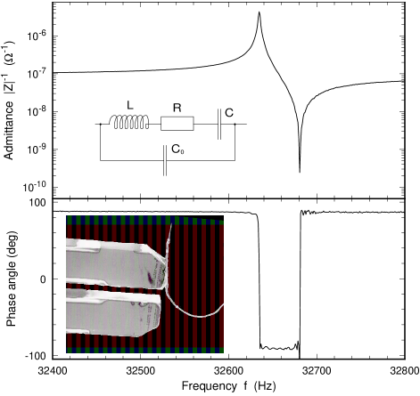
In order to implement cheap and easy-to-make dynamic SFM operation at cryogenic temperatures we decided to avoid optical cantilever deflection detection and use piezoelectric tuning forks instead. Initially, quartz tuning forks have been developed for the realization of very small and stable oscillators in watches. Due to their use in industry they are cheap and easily available. Most of them have a (lowest) resonance frequency Hz and quality-factors in vacuum between and . In scanning probe microscopy they have recently found new applications as piezoelectric sensors[5, 6, 7, 8, 9, 10, 11, 12]. The high -values of tuning forks offer the advantage that dynamic mode operation under ambient conditions or in liquids is possible. However, low-temperature operation in the dynamic SFM-mode has not been demonstrated before. In our system the tuning fork is driven by an AC-voltage from a Yokogawa function generator FG320. This voltage is scaled down by a factor of 1000 with a voltage divider residing close to the microscope head, which leads to typical excitation amplitudes of 0.1-10mV. We directly measure the admittance of the tuning fork with a home-made current-voltage converter with a gain of 1V/A connected in series to the tuning fork. The mechanical tip amplitude depends linearly on the measured current and is typically between 1-100nm[5, 13]. Due to the high oscillator quality the power loss of the tuning fork at resonance can be far less than , which makes it ideal for the use in low cooling power cryostats. A typical resonance curve and a corresponding equivalent circuit is shown in Fig. 2. The mechanical resonator is modeled by the -branch in the equivalent circuit which leads to the admittance maximum. The capacitance between the electrodes described by leads to the asymmetry of the resonance curve with a minimum above the resonance frequency[13].
A tip made of W or PtIr wire with typical diameter of 20m is glued to one of the tuning fork arms in parallel to the direction of the vibrational motion of the arm (see inset of Fig. 2). The tip can be contacted separately. After mounting the tuning fork with the tip on the scanning head the tip is electrochemically etched to achieve tip radii of less than 30nm. After the preparation of a tip the resonance frequency of the tuning fork is shifted by about 100Hz to lower frequencies and the -value is lowered but can be kept above a value of 20000 in vacuum.
The tip prepared on the tuning fork can be used as a tunnelling tip (STM-mode) or as the tip in dynamic SFM operation mode without any modifications on the scanning head. This gives simultaneous access to two complementary imaging modes at low temperatures without the need of a tip exchange. The high stiffness of the tuning fork arms (static spring constant up to 2N/nm) is sufficient to guarantee stable tunnelling conditions.
IV Phase-locked loop
The principle of dynamic mode SFM operation of the tuning fork is the same as for normal cantilevers. The elastic interaction of the tip with the sample surface will shift the resonance frequency via the presence of force gradients. Inelastic tip-sample interactions will mainly alter the -value of the oscillator. With our setup we can use both quantities to control the z-piezo via the feedback loop, i.e. we can either keep the resonance frequency or the dissipated power constant during a scan.
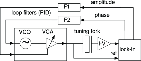
If driven at constant frequency, the high -values of tuning forks lead to a very slow response of the oscillation amplitude or phase on a steplike change in the tip-sample interaction on a time scale . The resulting limitation in bandwidth is undesirable since it makes SFM imaging very slow. A significant increase in the bandwidth can be achived with the use of a phase-locked loop[6, 8, 14]. Figure 3 shows the operation principle. The measured current through the tuning fork is analyzed electronically and its amplitude and phase (relative to the driving voltage) are determined. Both signals are fed back into the oscillator via two separate PID-components. The phase signal is used to modulate the excitation frequency and allows locking on a fixed value of the phase. In contrast to the detection of amplitude or phase changes at fixed driving frequency, the phase-locked loop gives a much faster response on the time scale needed for the determination of the signal phase, which is typically independent of the -value. This scheme allows us to achieve a bandwidth significantly larger than that of the -feedback loop. The latter is limited by the lowest mecanical resonance frequency of the scan piezo at around 1kHz.
When we prepare for scanning, we first measure the frequency response of the tuning fork to determine the actual resonance frequency . The phase-locked loop can then be set up with as the carrier frequency. The frequency of the function generator is controlled with a sensitivity set to - . The noise in the frequency is then of the order of in the range from 1Hz to 1kHz corresponding to 10 mHz peak-to-peak.
As an additional refinement we can use the measured amplitude of the tuning fork oscillation to feed it back into the amplitude modulation input of the oscillator. This additional feedback keeps the amplitude of the tuning fork oscillation at a fixed value by adjusting the amplitude of the excitation voltage.
V SFM operation
As the error signal for the feedback loop controlling the tip sample distance we use either the voltage proportional to the frequency shift (frequency control mode) or the change in driving voltage needed to keep the oscillation amplitude constant (amplitude control mode). Due to the size of our scan piezo its mechanical resonances allow a bandwidth of only 1kHz for the -control, i.e. this is the decisive factor limiting the overall bandwidth of our system. We therefore reach typical scan speeds of up to 10m/s.
Before the microscope is inserted into the cryostat, the sample is heated above 100∘C and the VTI is heated close to room temperature. After inserting the microscope we pump the VTI and cool down at a rate of 3K/min. The sample is kept 50K above the temperature of the gas flow in order to prevent freezing contaminations on the sample surface. For optimum operation a stable temperature gradient along the sample rod has to be maintained. The pressure, which strongly affects the resonance frequency, has to be stabilized below the vapor pressure of 4He in order to prevent liquid helium to enter the VTI. Operation in normal liquids (e.g. 4He or 3He) is possible but the -value and thereby the sensitivity is reduced by a factor of four. Below 2.2K, where 4He becomes superfluid, in our cryostat the resonance frequency becomes unstable, presumably due to thermodynamic instabilities. These problems, however, can be solved by operating the microscope in a vacuum beaker.
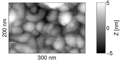
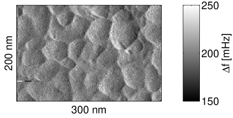
In the following we show two examples of SFM-operation at low temepratures. Fig. 4 shows the image of the surface of a 150nm gold film evaporated on a glass substrate. Small grains with a typical size of 30nm are resolved. The lateral resolution is better than 20nm, the resolution in -direction is better than 1Å. The upper image shows the topography and the lower image is the frequency shift, i.e. the error signal for the -feedback.
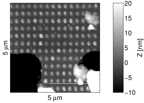
If one sets out to investigate semiconductor nanostructures, locating the structure of interest at low temperature where the scan range is only a few microns, is a significant problem. With the lateral coarse tip positioning we were able to find a 10mm spot on top of a GaAs/AlGaAs-heterostructure where a Hall-bar device had been fabricated by photolithography techniques. On top of a part of the Hall-bar a square lattice of oxide dots with a period of 400nm had been written by AFM-lithography[15]. Fig. 5 shows an image of this area of the sample taken at a temperature of 2.5K.
Operation of the head in a magnetic field of 8T shifts the scanned area by about 0.5m. It is therefore possible to scan at different fixed magnetic fields without loosing the structure of interest. Spectroscopy at a fixed point of the surface with sweeping magnetic field is difficult. The resonance frequency of the tuning fork is not found to shift significantly when the magnetic field is altered.
The design of our cryo-SFM, especially the low power dissipation of the tuning forks, makes it an ideal system for imaging at even lower temperatures in a 3He-cryostat or even a dilution refrigerator. In spite of the high stiffness of the tuning fork sensor compared to conventional SFM-cantilevers high sensitivity is achieved due to the large -values of the mechanical oscillator. The high stiffness allows the preparation of probes without a strong impairment of oscillator performance. It may offer the option in the future to fabricate other sensors, e.g. semiconductor chips, instead of or in addition to tunnelling tips at the end of one tuning fork arm. A straightforward continuation of the development of our system leads to the application of the scanned gate technique, Kelvin force microscopy and scanning capacitance microscopy.
VI Conclusion
In conclusion, we have implemented a low-cost dynamic mode cryo-SFM for operation down to temperatures below 4.2K and in magnetic fields up to 8T. Due to the utilization of piezoelectric quartz tuning forks there is no need for an optical cantilever deflection detection. The unit can be operated in STM-mode or SFM-mode without tip exchange. High bandwith is achieved with a phase-locked loop which controls the driving frequency of the tuning fork. Further development beyond the SFM-operation at low temperatures is feasible.
ACKNOWLEDGMENTS
The authors would like to thank H. Hug and K. Karrai for valuable discussions. Financial support by the Eidgenössische Technische Hochschule is acknowledged.
REFERENCES
- [1] D.V. Pelekhov, J.B. Becker, G. Nunes Jr, Appl. Phys. Lett. 72, 993 (1998).
- [2] M.A. Eriksson, R.G. Beck, M. Topinka, J.A. Katine, R.M. Westervelt, K.L. Campman, A.C. Gossard, Appl. Phys. Lett. 69, 671 (1996).
- [3] R. Crook, C.G. Smith, M.Y. Simmons, D.A. Ritchie, M. Pepper, 24th Int. Conf. on the Physics of Semiconductors, Jerusalem 1998.
- [4] M. Tortonese, R.C. Barrett, and C.F. Quate, Appl. Phys. Lett. 62, 834 (1993).
- [5] K. Karrai, R.D. Grober, Appl. Phys. Lett. 66, 1842 (1995).
- [6] H. Edwards, L. Taylor, W. Duncan, A.J. Melmed, J. Appl. Phys. 82, 980 (1997).
- [7] A.G.T. Ruiter, K.O. van der Werf, J.A. Veerman, M.F. Garcia-Parajo, W.H.J. Rensen, N.F. van Hulst, Ultramicroscopy 71, 149 (1998).
- [8] W.A. Atia, Ch.C. Davis, Appl. Phys. Lett. 70, 405 (1997).
- [9] J. Salvi, P. Chevassus, A. Mouflard, S. Davy, M. Spajer, D. Courjon, K. Hjort, L. Rosengren, Rev. Sci. Instrum. 69, 1744 (1998).
- [10] D.P. Tsai, Y.Y. Lu, Appl. Phys. Lett. 73, 2724 (1998).
- [11] M. Todorovic, S. Schultz, J. Appl. Phys. 83, 6229 (1998).
- [12] R. Steinke, M. Hoffmann, M. Böhmisch, J. Eisenmenger, K. Dransfeld, P. Leiderer, Appl. Phys. A 64, 19 (1997).
- [13] J. Rychen, T. Ihn, P. Studerus, A. Herrmann, K. Ensslin, in preparation.
- [14] T.R. Albrecht, P. Grütter, D. Horne, D. Rugar, J. Appl. Phys. 69, 668 (1991).
- [15] R. Held, T. Vancura, T. Heinzel, K. Ensslin, M. Holland, W. Wegscheider, Appl. Phys. Lett. 73, 262 (1998).