[
Model of surface instabilities induced by stress
Abstract
We propose a model based on a Ginzburg-Landau approach to study a strain relief mechanism at a free interface of a non-hydrostatically stressed solid, commonly observed in thin-film growth. The evolving instability, known as the Grinfeld instability, is studied numerically in two and three dimensions. Inherent in the description is the proper treatment of nonlinearities. We find these nonlinearities can lead to competitive coarsening of interfacial structures, corresponding to different wavenumbers, as strain is relieved. We suggest ways to experimentally measure this coarsening.
pacs:
68.55.-a, 64.60.My]
Elastic effects can strongly influence the morphology of materials, and hence influence material properties. If nonequilibrium elastic energies build up, there are different ways for solids to release that energy. One is by plastic deformation, involving dislocations, another is by elastic deformation, which is commonly seen in thin-film growth. A non-hydrostatically strained solid which is in contact with its own melt or vapor can partially release its elastic energy by a morphological instability at the interface. This strain relief mechanism gives rise to what appears to be a buckling of the surface into trenches, or islands, of a particular spacing. It was first predicted by Asaro and Tiller[1]. Experimentally, it has been observed and studied by Torii and Balibar[2] who strained He4 crystals non-hydrostatically as well by Berrébar et al. [3] in polymer crystals. Furthermore, it is often associated with the dislocation-free Stranski-Krastanov growth mode (also called island-on-layer mode) of epitaxially grown thin films as being observed for Ge/Si[4], InGaAs/GaAs[5] and InGaAs/InP[6]. Since the independent rediscovery of the instability by Grinfeld[7] and Srolovitz[8], it is often referred to as the Grinfeld instability.
Several approaches have been employed to study the instability. They are either based on static energy minimization calculations by a variational principle [7], or on a dynamical interface equation which describes mass transport, mainly surface diffusion, under the influence of the chemical potential which comprises surface free energy and elastic energy [8, 9, 10, 11, 12, 13, 14]. Linear stability analysis[8, 10, 11] predicts conditions for the onset of instability. Spencer and Meiron [13], and Yang and Srolovitz[14] studied the nonlinear evolution numerically, whereby the surface profile evolved to smooth flat peaks with sharp deep grooves. These studies have been limited to dimension : Within the interface formulation, unphysical sharp cusps form within the grooves, leading to numerical stability problems [13]. To make connection to experiments, one requires a model which comprises a full nonlinear description, and which can be used in three dimensions.
In this paper, we present a Ginzburg-Landau phase-field model of the phenomena. An order parameter field determines whether one is in a hard solid phase, which supports shear, or a soft disordered phase, hereafter called the liquid phase, which does not. The position of the interface coincides with the rapid variation of this field. Such an approach has been applied successfully to other moving-boundary-value problems, such as phase segregation and crystal growth [15]. Indeed, our model is numerically robust, can be implemented in three dimensions, and is readily generalizable. We show below that we recover the Grinfeld instability in linear and highly nonlinear regimes. We furthermore probe the transient dynamics during the morphological instability, finding that competitive coarsening of interface structures takes place. We suggest ways to measure this experimentally.
The physical mechanism for the stress-driven morphological instability can be understood easily. A stressed solid can partially relieve its stress by differentially moving material from valleys to hills, buckling at a particular wavenumber. In the less constrained peaks, lateral relaxation occurs, unlike in the more constrained valleys. The resulting stress gradient drives the instability by creating deeper valleys, thereby increasing the stress gradient, and sustaining the growth of the perturbation. At sufficiently small length scales, capillarity prevents the formation of sharp cusps.
The model we propose is based on a Ginzburg-Landau approach in which the elastic strain is a subsidiary tensor variable coupled to a nonconserved scalar order parameter. This approach is related to that of Onuki [16, 17], Onuki and Nishimori[18], and Sagui, Somoza, and Desai [19], which was used to analyze elastic effects in phase-separating alloys [20]. The coarse-grained Ginzburg-Landau free energy is:
| (1) |
where integration over is indicated by the subscript on the integral, is the strain and is the displacement field. The bulk free energy density is given by:
| (2) | |||||
| (3) |
where the first term describes a three-well potential with being the liquid and the solid phase, ensuring that the liquid-solid phase transition is first order. The potential depths are determined by the model parameter , which together with the parameter being proportional to the surface tension, determines the interfacial thickness. The second term shifts the energy, so that, for constant elastic coefficients, solid and liquid are at coexistence. The convenient choice guarantees [15] that both bulk phases keep their equilibrium values (liquid) and (solid). The coupling constant is related to the externally applied stress. The trace of the strain tensor is , and is the isotropic elastic free energy[21]:
| (4) |
where is the compressibility, and is the shear modulus in the solid phase alone. By construction, the shear modulus in the soft liquid phase is zero, whereas it stays nonzero and constant in the hard solid phase. Since the the solid phase supports shear, whereas the liquid phase does not, our phase-field order parameter has a transparent meaning in the context of the liquid-solid transition.
It is reasonable to suppose that the elastic field relaxes much faster than . Then the elastic field can be solved in terms of the order parameter using the condition of local mechanical equilibrium: , where a summation convention over repeated indices is implicit. The stress tensor, , is then given by
| (5) |
The solution of this to first order in the shear modulus is:
| (6) | |||||
| (7) |
where ,
| (8) |
, and . In the absence of external strain, that is , the solid will be stressed whereas the liquid is stress-free. For a flat surface , the solution of Eq. (8) in two dimensions is and . Therefore, the solid will be uniaxially strained with determining the strength of that strain.
The elastic field can now be expressed in terms of the order parameter. Substituting the solution for the strain field gives the free energy in terms of alone. The long-range character of the elastic field appears through . Assuming relaxational dynamics, the equation of motion is given by:
| (9) |
with being the mobility and
| (10) | |||||
| (11) |
Rescaling length and time scales where is a characteristic length scale, such as the wavelength of the perturbation, , rescales the parameters to , and . We obtain a dimensionless equation of motion:
| (12) |
with three parameters , , and , giving the mobility, capillarity, and shear strength, respectively.
Numerical simulations on a discrete lattice were performed in two and three dimensions. Euler’s method was used for the integration in time. The Green function was solved in Fourier space. For all simulations presented here the mesh size or , the time step or , , and . This choice of and guarantees that the surface is resolved by at least 8 points. The parameter set, (, , , , ) will be specified below, where gives the initial amplitude of the surface. Length scales will be measured in units of . Periodic boundary conditions were employed in all direction. Thus, the solid was in contact with its liquid phase at the bottom and at the top. It was ensured that the solid was sufficiently thick that the interfaces at the top and bottom acted independently.
A numerical linear stability analysis was performed in two dimensions. The system was prepared with a small amplitude sinusoidal surface profile , where is wavenumber, and its subsequent evolution was monitored. We found that the growth of the amplitude of the Fourier modes was initially independent and exponential, obeying , followed by slower constant velocity growth. The fitted dispersion is consistent with , where and . See Fig. 1. Perturbations with wavenumber larger than a critical wavenumber are stabilized by surface tension, whereas wavenumbers smaller than the critical wavenumber are unstable, therefore being a long wavelength instability. The flat interface however is stable. This agrees with the linear stability analysis carried out by Srolovitz[8] for the case where evaporation-condensation is the material transport mechanism, which is appropriate for our model.

Linear stability analysis predicts only the condition of onset of instability. To study the later-stage morphology, a complete nonlinear description has to be employed. One advantage of the phase-field description is that nonlinearities are taken into account implicitly. A typical set of configurations is shown in Fig. 1. The nonlinear effect gives rise to a clear asymmetry between peaks and valleys, wherein deep grooves appear in the valleys. This behavior has been observed experimentally, as well as in previous theoretical studies [9, 12, 13, 14]. Unlike previous studies, no numerical instabilities limit the study of the formation of the grooves here. It is interesting to note that in the early stages of the instability we can fit the interfacial profile with a simple function , where the curvature is a low-order polynomial function of the height of the interface.
Experimentally, random fluctuations in the interface will give rise to the competitive growth of different structures corresponding to different wavenumbers. To study this, we prepared the system with an interfacial profile consisting of a superposition of linearly unstable modes, with and being a uniformly distributed random variable in the interval .

We did 100 runs over 500 time steps of a two-dimensional system with 100 unstable modes, where (, , , , ) (1024, 512, 0, 0.24, 11). Figure 2 shows the Fourier transform of the equal-time height-height correlation function, which we shall call the structure factor . For early times, there is a strong similarity between this behavior and early-stage spinodal decomposition in long-range force systems [22]; we show the results of a linear Cahn-Hilliard-type theory of the modes in the figure as well. Note that the structure factor vanishes for due to elasticity, not a conservation law. For later times, when the linear theory no longer describes the data, coarsening is evident: The location of the peak of the structure factor moves to smaller wavenumbers, as the peak height increases and sharpens. The peak height follows , where , while the peak width sharpens with time as , where . The former dependence is due to the total interface length increasing linearly with time for any unstable wavenumber. The latter dependence is due to competitive ordering between different wavenumbers, analogous to phase ordering. Within the accuracy of our study, we find that the structure factor shows scale invariance: , where the scaled wave number . See Fig. 2. Fitting to and , for small and large respectively, gives , and .
Although these results were obtained in two dimensions, we expect qualitatively similar results in three dimensions. To show this, we simulated a system with , with being the direction normal to the surface.
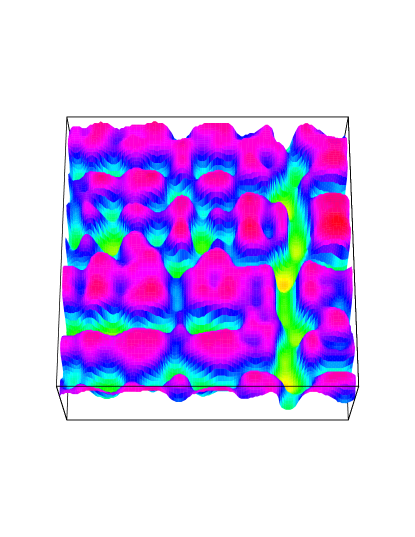
Starting with a small amplitude sinusoidal perturbation in , trenches with sharp deep grooves form, while a small amplitude sinusoidal perturbation in the and directions resulted in islands. The instability is qualitatively the same as in two dimensions. Starting with a superposition of unstable modes, coarsening was again observed. Figure 3 shows the interfacial profile while coarsening is taking place. We expect that our results on transient coarsening phenomena can be observed through microscopy or by x-ray diffraction [23].
To conclude, our model recovers the main features of the Grinfeld instability. Our description can be easily extended. Anisotropic effects can included through the surface tension, the elastic coefficients, or the external stress. The effect of phase separation or of impurities can be studied by coupling an additional field to the phase field. Instead of evaporation-condensation, surface diffusion can be chosen as the material transport mechanism, and, in addition, the influence of a constant flux can be studied. Finally, we note that in some cases the stress field at the groove tip can become so high that dislocations can be nucleated [5, 24]. To study this, we are presently extending our model by coupling the phase field to a dislocation density field.
We thank Karim Aguenaou and Celeste Sagui for useful discussions. This work was supported by the Natural Sciences and Engineering Research Council of Canada, and le Fonds pour la Formation de Chercheurs et l’Aide à la Recherche du Québec.
REFERENCES
- [1] R. J. Asaro and W. A. Tiller, Metall. Trans. 3, 1789 (1972).
- [2] R. H. Torii and S. Balibar, J. Low Temp. Phys. 89, 391 (1992).
- [3] J. Berréhar, C. Caroli, C. Lapersonne-Meyer and M. Scott, Phys. Rev. B 46, 13487 (1992).
- [4] M. Horn von Hoegen, in Surface Diffusion, Atomistic and Collective Processes, NATO ASI Series, edited by M. C. Tringides, (Plenum Press, New York, 1996) p. 309.
- [5] S. Guha, A. Madhukar, and K. C. Rajkumar, Appl. Phys. Lett. 57, 2110 (1990).
- [6] T. Okada, G. C. Weatherly, and D. W. McComb, J. Appl. Phys. 81, 2185 (1997).
- [7] M. A. Grinfeld, Doklady Akademii Nauk SSSR 265 836 (1982) M. A. Grinfeld, Sov. Phys. Dokl. 31, 831 (1986) M. A. Grinfeld, Europhys. Lett. 22, 723 (1993), and references therein.
- [8] D. J. Srolovitz, Acta Metall. 37, 621 (1989).
- [9] P. Nozière, in Solids Far from Equilibrium, edited by C. Godrèche (Cambridge University Press, Cambridge, 1992) p. 1.
- [10] B. J. Spencer, P. W. Voorhees, and S. H. Davis, Phys. Rev. Lett. 67, 3696 (1991).
- [11] B. J. Spencer, P. W. Voorhees, and S. H. Davis, J. Appl. Phys. 73, 4955 (1993).
- [12] B. J. Spencer, S. H. Davis, and P. W. Voorhees, Phys. Rev. B 47, 9760 (1993).
- [13] B. J. Spencer and D. I. Meiron, Acta metall. mater. 42, 3629 (1994).
- [14] W. H. Yang and D. J. Srolovitz, Phys. Rev. Lett. 71, 1593 (1993).
- [15] R. Kobayashi, Physica D 63, 410 (1993).
- [16] A. Onuki, J. Phys. Soc. Jpn. 58, 3065 (1989).
- [17] A. Onuki, J. Phys. Soc. Jpn. 58, 3069 (1989).
- [18] A. Onuki and H. Nishimori, Phys. Rev. B 43, 13649 (1991).
- [19] C. Sagui, A. M. Somoza, and R. C. Desai, Phys. Rev. E 50, 4865 (1994).
- [20] The growth of islands on surfaces, deformed into quasi-dendritic morphologies by elastic forces, is studied by K. Aguenaou, J. Müller, and M. Grant (preprint).
- [21] L. D. Landau and E. M. Lifshitz, Theory of Elasticity, (Pergamon Press, Oxford, 1986)
- [22] M. Laradji, M. Grant, M. J. Zuckermann, and W. Klein, Phys. Rev. B 41, 4646 (1990), and references therein.
- [23] S. K. Sinha, E. B. Sirota, S. Garoff, and H. B. Stanley, Phys. Rev. B 38, 2297 (1988).
- [24] L. Dong, J. Schnitker, R. W. Smith, and D. J. Srolovitz, J. Appl. Phys. 83, 217 (1998).