Resonant tunneling diode with spin polarized injector
Abstract
We investigate the current–voltage characteristics of a II-VI semiconductor resonant-tunneling diode coupled to a diluted magnetic semiconductor injector. As a result of an external magnetic field, a giant Zeeman splitting develops in the injector, which modifies the band structure of the device, strongly affecting the transport properties. We find a large increase in peak amplitude accompanied by a shift of the resonance to higher voltages with increasing fields. We discuss a model which shows that the effect arises from a combination of three-dimensional incident distribution, giant Zeeman spin splitting and broad resonance linewidth.
pacs:
72.25.Dc, 85.75.MmOne of the interesting designs for eventual spintronics devices are structures based on magnetic semiconductor resonant tunneling diodes (RTDs) which have promising futures as spin filters and spin aligners. However, before these structures can make their way into actual devices, we must first understand the basic behaviors of these magnetic structures and how they differ from their non-magnetic counterparts. Early studies into magnetic semiconductor tunneling structures have reported spin injection from either paramagnetic or ferromagnetic semiconductor fidi ; aw into non-magnetic light emitting diodes. A primary tradeoff between these two options is that while ferromagnets allow for non-volatile operation without an external magnetic field, they can thus far only be made p-type, and the short mean free path of holes compared to electrons significantly reduces coherent transport phenomena. Using paramagnetic semiconductors, we have previously explored the behavior of RTDs with a magnetic quantum well by optical waag and electrical means, slo03 and now turn our attention to RTDs fitted with magnetic injectors. Here, the polarization of spin originates in the bulk behavior of the injector, and the RTD itself is essentially a non-magnetic device which is fed with a polarized source of electrons. As a magnetic field increases, we observe important changes in the transport characteristics of the RTD stemming from the realignment of the band profile in the device, and explain how this can be understood in the framework of a Landauer-Büttiker–type model. A correct understanding of this mechanism is therefore essential before proceeding to more sophisticated device structures combining spin injection, detection and manipulation.
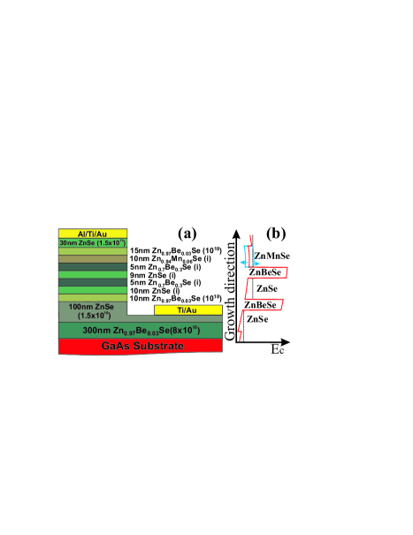
The studied sample is an all-II-VI semiconductor resonant tunneling diode structure with a conduction band profile similar to that used in previous work on II-VI and III-Vslo03 based RTD and fitted with a dilute magnetic semiconductor (DMS) injector layer. The tunneling region consist of a 9 nm thick ZnSe quantum well (QW) sandwiched between two 5 nm thick Zn.7Be.3Se barriers. Below the tunneling region is a 10 nm thick ZnSe collector layer. The injector is a 10 nm thick Zn.94Mn.06Se layer used to inject spin polarized electrons into the diode. The remaining layers are needed to ensure a proper doping profile and to allow for the fitting of high quality ohmic contacts. Full details of the layer stack are given in Fig. 1(a).
The contact resistance of the devices is kept to a minimum by using an in-situ Al(10 nm)/Ti (10 nm)/Au (30 nm) top contact, while the ex-situ bottom contact is fabricated by etching down to the very highly doped ZnSe layer, and using large area (500m Ti-Au contact pad. The sample is patterned in 100 m2 pillars using standard optical lithography, wet each and lift-off.
Measurements are performed in 4He bath cryostat equipped with a high field superconducting magnet using standard DC transport techniques. Care was taken to construct a circuit with a low (40 ) resistor in parallel to the diode to prevent the diode from going into oscillations in the negative differential conductance region. Leadb . Current measurements consist of measuring the voltage drop across a relatively small 30 Ohm series resistor.
A schematic of the band profile is shown in Fig. 1. Both the injector and collector sides of the tunneling structure are gradient doped in order to insure a relatively low Fermi energy at the point of injection, and thus a sharp resonance Wie . Under the influence of an external magnetic field, the DMS injector exhibits a giant Zeeman splitting of up to 20 mV, and the degeneracy of its spin states is lifted following a Brillouin function Gaj , creating a spin polarized carrier population via the transfer of electrons from the higher energy spin band to the lower one. In order to maintain proper alignment of the Fermi energy, this imbalance in the population of the two spin species must lead to a splitting of the bottom of the spin up and spin down conduction bands, leading to different band profiles for each of the spin species in the injector region, and indicated in the diagram.
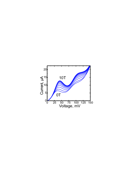
Current-voltage characteristics for the device for different amplitudes of perpendicular-to-plane magnetic fields () are shown in Fig. 2. At zero field, the sample exhibits typical RTD behavior, showing a strong resonance peak at 36 mV with a peak to valley ratio just over 1. The additional resonance visible at 96 mV in the curve is the well known LO phonon replica Leadb which is separated from the direct resonance by the energy of the LO phonon of the well material, and can be used to calibrate the voltage scale to the energy of the levels in the QW. A resonance associated with the second well level occurs at around 0.3 V (not shown in the figure). Because of the intrinsic asymmetry of the device due to the presence of the GaAs substrate, the resonances for the negative bias direction are not as pronounced. We confirmed the absence of charging effects in the device by verifying that I-V curves for different sweep direction were identical Martin .
As a magnetic field is applied, the peak shifts to higher voltages and strongly increases in amplitude. The strongest dependence of the peak amplitude and position on the magnetic field is observed at low fields, with the behavior saturating before 10 T. The behavior is therefore consistent with the Brillouin like behavior expected from the giant Zeeman splitting of the injector. Note also that the phonon replica causes a higher energy echo of the QW state, but since the effects we are studying result from properties of the injector, the phonon replica peak simply follows the magnetic field dependance of the main resonance.
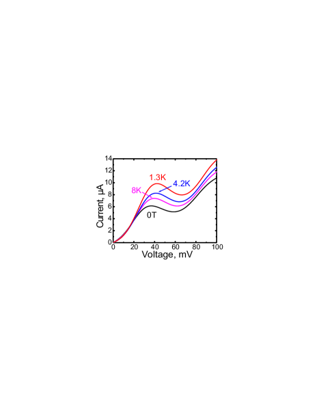
Figure 3 shows the temperature dependence of the 2 T I-V curve for temperatures from 1.3 to 8 K. The curve, which is temperature independent in this range, is included for comparison. It is clear that the increase in temperature has an identical effect on the I-V curves as would a lowering in the magnetic field. Indeed, we verified that the only effect of temperature is to rescale the effect of the magnetic field on the Zeeman splitting in the injector exactly as would be expected from the fact that the argument of the Brillouin function scales as as described below.
The slight shift of the peak to higher bias with increasing magnetic field is fairly intuitive and can be directly expected from the schematic of Fig. 1b. It is well established that the maximum of the resonance occurs when the bottom of the conduction band is brought into alignment with the well level lur85 . As the field increases, the peak becomes more and more dominated by the majority spin conduction band. Since the bottom of this band is moving to lower energies, a higher bias will be required to bring this band in alinement with the well level, producing a shift of the resonance towards higher bias.
The strong increase in the current amplitude is similarly related to the change of the conduction band energy with magnetic field , but its manifestation is somewhat more subtle. Let denote the spin-split band bottom with the spin splitting [() for ()]. Due to the exchange interaction between localized Mn ions and band electrons a giant Zeeman splitting arises in the DMS which is known to be given by:
| (1) |
where is the exchange integral, the Mn concentration of Mn spins, is the Lande factor, the Brillouin function, and and are the Mn effective spin and temperature, respectively. One might naively expect that a spin splitting of the conduction band leaves the DMS injector electron density constant (keeping fixed). This is indeed correct for a 2D injector san02 since the spin-dependent density is independent of energy because the density of states is constant. However, for a 3D system depends nonlinearly on , so that (as we will show below) the total electron density is an increasing function of provided is kept fixed. Since the current peak is mainly determined by , it follows from Eq. (1) that the peak amplitude increases with . Therefore, the current increase effect has a geometrical origin.
To gain further insight, we perform numerical simulations of the electron transport along the -direction [growth direction, see Fig. 1(b)]. Because a similar peak amplitude increase is also observed when is an in-plane magnetic field indicating that the effect is independent of the direction of the magnetic field, orbital effects are not taken into account. In addition, we neglect spin relaxation effects and the current density is thus carried by both spin species in parallel,
with the bias voltage applied to the structure. While this assumptions limits the model to the case of coherent transport, the good agreement it shows with experience suggests that this assumption is reasonable for the device in question. We take the spin splitting into account in the longitudinal energy . The Fermi functions and describe the distribution of electrons with total energy in the left and right leads with electrochemical potentials and , respectively. Band-edge effects are incorporated in the lower limit of the integral.
In Eq. (Resonant tunneling diode with spin polarized injector), the transmission conserves the momentum parallel to the interfaces and depends, quite generally, on , and the sub-band bottom energy of the quantum well. Close to resonance, it is a good approach to take a Lorentzian shape, , where ( is the partial decay width due to coupling to lead L (R) and the total broadening per spin. We consider symmetric barriers for simplicity but note that it is important in the strongly nonlinear regime (i.e., around the current peak) to take into account the energy (and voltage) dependence of the tunneling ratesbla99 . The barrier height is given by the conduction band offset between ZnSe and Zn0.7Bee, which is approximately eV. Using ZnSe parameters we find for the first resonant level meV. Spin saturation takes place at around meV, thereby meV. This implies that for small resonance width the onset of the – curves of Fig. 2 should occur at meV. This fact, together with the low peak-to-valley ratio that the – curves exhibit, suggests a large value of , probably due to disorder or interface roughness. Therefore, we set meV at and and fit the peak current at with the experimental value.
We show the results in Fig. 4 from to . The – curves reproduce the experimental observations and the agreement is fairly good. The negative differential conductance region extends from the resonance peak because we consider only the first resonant level and neglect non-resonant contributions to the tunneling current. In Fig. 4 the voltage axis is scaled with a lever arm , consistent with that extracted from the position of the phonon replica. Since the broadening is a large energy scale, we can expand Eq. (Resonant tunneling diode with spin polarized injector) at zero temperature in powers of . We find for small spin splitting that the resonance peaks at clearly shows the shift of with increasing . Substituting the parameters, we obtain mV at , in accordance with Fig. 2. Moreover, inserting this result in Eq. (Resonant tunneling diode with spin polarized injector) we find to leading order in that the peak current is indeed an increasing function of the magnetic field. In the inset of Fig. 4 we present the current peak as a function of , showing a remarkable agreement with the experimental observations. We note that since the only experimental effect of varying the temperature is a rescaling of , this model is equally valid for the temperature dependent data. For comparison, we provide the current increase when the energy dependence of is neglected, which qualitatively agrees with our results, indicating that the simple model (Resonant tunneling diode with spin polarized injector) captures the key points of the experiment. Conceptually, this result can be viewed as resulting from the change in the position of the conduction band in the injector which is required to maintain the alignment of the Fermi level throughout the device while allowing for the magnetic field induced redistribution of spin populations. This pushes down the bottom of the majority spin conduction band, which thus requires a higher bias to be brought into alignment with the well level, and consequently moves the maximum of the resonance to higher bias. Additionally, the redistribution of the spin population increases the size of the Fermi sphere of the majority band, providing more states at the Fermi energy available for tunneling, and thus increasing the current.
Indeed, the results we obtain are reminiscent of Ref. cho92, , where the In content of a GaInAs emitter in a III-V RTD was varied. As a consequence, the band alignment changes similarly to our present structure, and the peak current increases. In our case, the increase is due exclusively to the giant spin splitting in the injector. Thus, the current increase can be tuned with a magnetic field without changing the sample parameters.
In conclusion, we have presented – characteristics of a II-VI resonant-tunneling diode attached to a diluted magnetic semiconductor injector. We have observed both an enhancement and a voltage shift of the resonance current peak when the applied magnetic field increases. The results are consistent with a giant Zeeman splitting in the injector since the current saturates at a few Tesla and the temperature dependence follows the magnetization of a paramagnetic system. The Zeeman splitting induced redistribution of spin carriers in the injector leads to a modification of the conduction band structure, causing a lowering of the majority spin conduction band and an increase of available states for tunneling, which in turn is responsible for the changes in transport properties. We have discussed a transport model which replicates most of the features seen in the experiment. Our findings offer the unique possibility of producing high peak currents which arise from spin effects only.
Acknowledgments.—The authors thank M. Büttiker for useful discussions and V. Hock for sample fabrication, as well as Darpa SpinS, ONR, SFB 410, BMBF, RTN, and the “Ramón y Cajal” program for financial support.
References
- (1) R. Fiederling, M. Keimi, G. Reuscher, W. Ossau, G. Schmidt, A. Waag, and L.W. Molenkamp, Nature (London) 402, 787 (1999).
- (2) Y. Ohno, D.K. Youn, B. Beschoten, F. Matsukura, H. Ohno and D.D. Awschalom, Nature (London) 402, 790 (1999)
- (3) Th. Gruber, M. Keim, R. Fiederling, G. Reuscher, W. Ossau, G. Schmidt, L.W. Molenkamp, Appl. Phys. Lett. 78 (2001) 1101
- (4) A. Slobodskyy, C. Gould, T. Slobodskyy, C.R. Becker, G. Schmidt, and L.W. Molenkamp, Phys. Rev. Lett. 90, 246601 (2003).
- (5) J. A. Gaj, R. Planel, G. Fishman, Solid State Commun. 29, 435 (1979).
- (6) C.R Wie and Y.W. Choi, Appl. Phys. Lett. 58, 1077 (1991).
- (7) M.L. Leadbeater, E.S. Alves, L. Eaves, M. Henini, O.H. Hughes, A. Celesta, J.C Portal, G. Hill, and M.A. Pate, Phys. Rev. B, 39, 3438, (1989).
- (8) A.D. Martin, M.L.F. Lerch, P.E. Simmonds and L. Eaves, Appl. Phys. Lett. 64, 1248 (1994).
- (9) S. Luryi, Appl. Phys. Lett. 47, 490 (1985).
- (10) D. Sánchez, A.H. MacDonald, and G. Platero, Phys. Rev. B 65, 035301 (2002).
- (11) Ya. Blanter and M. Büttiker, Phys. Rev. B 59, 10217 (1999).
- (12) Y.W. Choi and C.R. Wie, J. Appl. Phys. 71, 1853 (1992).