Surface Spin-Flop Transition in a Uniaxial Antiferromagnetic Fe/Cr Superlattice Induced by a Magnetic Field of Arbitrary Direction
Abstract
We studied the transition between the antiferromagnetic and the surface spin-flop phases of a uniaxial antiferromagnetic [Fe(14 Å)/Cr(11 Å]x20 superlattice. For external fields applied parallel to the in-plane easy axis, the layer-by-layer configuration, calculated in the framework of a mean-field one-dimensional model, was benchmarked against published polarized neutron reflectivity data. For an in-plane field applied at an angle with the easy axis, magnetometry shows that the magnetization vanishes at , then increases slowly with increasing . At a critical value of , a finite jump in is observed for , while a smooth increase of is found for . A dramatic increase in the full width at half maximum of the magnetic susceptibility is observed for . The phase diagram obtained from micromagnetic calculations displays a first-order transition to a surface spin-flop phase for low values, while the transition becomes continuous for greater than a critical angle, . This is in fair agreement with the experimentally observed results.
pacs:
75.70.-i, 75.50.Ee, 75.10.-b, 75.30.KzI Introduction
It is well known that when a magnetic field applied along the easy axis of a uniaxial antiferromagnet exceeds a critical value , where is the exchange field and is the anisotropy field, the system undergoes a first-order phase transition to a bulk spin-flop phase, characterized by sublattice magnetizations nearly perpendicular to the field direction.neel ; callen In the case of a uniaxial antiferromagnet with one or two surfaces, which break the translational invariance in the direction perpendicular to the surface plane, the problem of determining the ground-state spin configuration in the presence of an external magnetic field applied along the in-plane easy axis was theoretically posed a few decades ago. The first model to be investigated was that of a semi-infinite stack of ferromagnetic planes, antiferromagnetically coupled and subject to a magnetic field antiparallel to the magnetization of the surface plane. For this system, when the ratio between and is very small (), the onset of a surface spin-flop phase was predicted using a continuum approximation.mills ; keffer This phase is characterized by a canting near the surface and is stable for field values greater than a critical value . Nearly a decade ago, the existence of such a surface spin-flop phase was criticizedmap ; review because a discrete, nonlinear map approach showed that the instability of the antiferromagnetic configuration at simply leads to an interchange of the two sublattices.map ; review Subsequently Pokrovsky and Sinitsynpokrovsky showed that, for a semi-infinite film with , a quite similar result can be obtained also in the continuum approximation, provided that appropriate boundary conditions are assumed.
The case of a finite stack with an even number of planes (but still ) is quite different since, for , the system tends to realize an inhomogeneous configuration with the magnetizations of both surfaces parallel to the field direction, and a domain wall is thus located in the center of the stack. For the stable state of the finite film is a different inhomogeneous configuration, with the inner spins assuming nearly the bulk spin-flop configuration and the surface ones less deviated with respect to the field direction.review
Fullerton et al.baderprb showed that the Fe/Cr(211) superlattice, obtained by the repetition of ferromagnetic iron layers antiferromagnetically coupled through the Cr spacer, constitutes an excellent model system of a finite uniaxial antiferromagnetic film. Since then, a great number of paperswangprl ; wmprb ; mapchaos ; micheletti ; trallori ; dantas ; tevelthuis ; rossler1 ; rossler2 ; rossler3 ; rbarxiv have been devoted to the study of the surface spin-flop phase transition. In fact, for sufficiently low thickness of the Fe layers, the system possesses a dominant uniaxial in-plane anisotropy along the Fe[ 0 -1 1] direction, with of the same order of magnitude as . For example, the Fe/Cr(211) superlatticewangprl with thickness Å and Å had an anisotropy-to exchange ratio , while for the system investigated in the present work and in Ref. tevelthuis, , with Å and Å, one has . This is a major difference with respect to ordinary antiferromagnets, like MnF2, where is usually much smaller (). The consequence of an increased value of in superlattices with respect to bulk antiferromagnets was investigated both experimentallywangprl and theoreticallywmprb ; mapchaos in Fe/Cr(211) superlattices with , and was found to introduce a sequence of sudden jumps in the field dependence of the magnetization, in addition to the surface spin-flop jump occurring at .
Recently, an accurate and systematic study of the phase diagram of a uniaxial antiferromagnetic film with an even number of planes was performed by Rößler and Bogdanovrbarxiv using an efficient conjugate gradient minimization technique in the case of the external magnetic field applied precisely along the easy axis. For , they found that there is only a first-order transition from the collinear antiferromagnetic (AF) phase to a symmetric, inhomogeneously flopped phase with the spin-flop (SF) located in the center of the film. For , their calculations of the spin configuration confirmed previous theoretical findings.wangprl ; mapchaos ; micheletti In fact they found a series of canted, asymmetric phases (Ci), separated by first-order transition lines, between the AF and the SF phases.rbarxiv Within these intermediate C phases, the ground state of the system evolves from a canted configuration with a flop localized near one of the surfaces (C1) to other configurations (C2, C3, …) where the flop moves into the center, causing abrupt variations of the magnetization as the field intensity is increased.rbarxiv ; mapchaos Finally, upon further increasing the anisotropy (), they found that only first-order transitions between collinear (antiferro-, ferri- and ferromagnetic) states are possible.rbarxiv
While the magnetic phase diagram of the finite AF film has been extensively investigated both theoretically and experimentally in the case of applied parallel to the easy axis, no such studies are known for the case for which is applied in-plane along an arbitrary direction with the easy axis. In the bulk case, the field-induced phase transition of a uniaxial antiferromagnet in the presence of a skew field forming an angle with the easy axis was theoretically studied by Rohrer and Thomasrohrer using a mean-field approach and then by Fisher et al.fisher ; kosterlitz Neglecting zero-point motion effects, they determined the equilibrium configurations as a function of the skew field, and found that the phase boundary between the AF and the bulk SF phase extends only to a maximum angle with respect to the easy axis, where it ends in critical points. More precisely, they predicted the first-order SF transition to become continuous (i.e., second-order) for greater than a critical angle (bulk). This expression, first developed for a tetragonal system, was later found to be valid for an orthorhombic system, when is restricted to a plane comprising the easy and intermediate axes.blazey
The small values of (bulk) in ordinary bulk antiferromagnets (amounting to a few tenths of a degree) made the observation of the crossover from first- to second-order in the transition difficult. Early results on MnF2 were, in this respect, only qualitative. More direct evidence of the crossover character of the transition was provided by Butera et al.butera by measuring the staggered magnetization of of MnCl4H2O. However, the existence and nature of a bicritical point was proven by measuring the critical magnetic scattering of a number of systems, notably CuCl2H2O,lynn CsMnBr2H2O,bastee and the above mentioned MnCl4H2O. On intuitive grounds, one might expect that in Fe/Cr(211) superlattices, a similar crossover effect in the order of the surface SF transition should be present and should be more easily observable owing the higher value of the ratio ( or more) compared to ordinary bulk antiferromagnets like MnF2, where .
The aim of the present paper is twofold: i) to extend to the film (i.e. finite) case the theoretical study of the magnetic phase diagram of a uniaxial antiferromagnet in a skew field, and ii) to provide experimental evidence that, in contrast with bulk antiferromagnets, in the case of the [Fe(14 Å/Cr(11 Å)]x20 superlattice, the crossover in the order of the surface SF transition with increasing skew field might be observed. Concerning the theoretical analysis, in Sec. II we present two different approaches, the nonlinear map method and the Landau-Lifshitz-Gilbert micromagnetic simulation, for the ground state and full hysteresis calculations, respectively. In Sec. III experimental results are presented and discussed, obtained by different techniques, both for parallel to the easy axis () and for a skew field (). Finally, conclusions are drawn in Sec. IV.
II Film model and theoretical framework
We consider a film made of an even number, , of parallel ferromagnetic planes that are antiferromagnetically coupled one to each other by a nearest neighbor exchange interaction and subject to a uniaxial in-plane anisotropy. For thin magnetic layers, the magnetostatic dipolar interaction is known to confine the spins to the film plane, so that, at equilibrium, the spins are necessarily in-plane and the dipolar energy is zero. One can therefore characterize the spin configuration of the -th plane by only one parameter, namely the angle that the magnetization of the -th plane forms with the axis (i.e., with the easy anisotropy axis) within the film plane . A magnetic field is applied in the film plane along a direction that forms an angle with . At K the energy density of the system takes the form:
| (1) | |||||
| (2) | |||||
| (3) |
where denotes the number of spins within each film layer, and , and .
The equilibrium spin configurations can be obtained from (1) by -derivation ()
| (4) | |||||
| (5) | |||||
| (6) | |||||
| (7) |
In the present work, the ground state of the one-dimensional (1D) model (1) that approximates the film has been determined using two different theoretical methods, namely: i) an integration of the Landau-Lifshitz equation for the spin chain, introducing a damping coefficient in order to reach the magnetic ground state (see Sec. II.A), and ii) a reformulation of Eq. (4), which provide the equilibrium conditions in terms of a nonlinear map with opportune boundary conditions at the film surfaces (see Sec. II.B). A comparative discussion of the two methods is made in Sec. II.C.
II.1 Spin configuration via integration of the Landau-Lifshitz-Gilbert equation
The Landau-Lifshitz-Gilbert (LLG) equationlandau
| (8) | |||||
| (9) |
describes the physical path of the magnetic moment in a field . Here and are the gyromagnetic ratio of the free electron spin and the Gilbert damping coefficient respectively, is the saturation magnetization, and is the local effective magnetic field. For thin magnetic layers, a large value of is appropriate because the demagnetizing field confines the magnetic moment to the film plane, suppressing the gyromagnetic precession and leaving an in-plane rotation of the moment towards the direction of the local effective field. Thus, the integration of the LLG equation becomes a simple relaxation of the magnetic moment along the energy gradient. In the numerical calculations, we iteratively rotate spins that represent individual Fe layers by an amount proportional to the torque at each instant. is then evaluated from the resulting configuration and applied to the next iteration. Upon reaching convergence, the stability of the equilibrium is tested by evaluating the eigenvalues of the stability matrix .wmprb ; dantas All eigenvalues of the stability matrix must be positive for the state to be stable. In the event of an unstable equilibrium, the configuration is displaced by a random, small fraction along the eigenvector direction for which the eigenvalue is negative, and the relaxation process starts anew until the system reaches a stable local energy minimum.
II.2 Determination of the energy minima via the nonlinear map method
A different approach for the determination of the ground state of the magnetic system described by Eq. (1) was proposed some years ago.map ; mapchaos ; review It is based upon a reformulation of the equilibrium conditions (4) of the magnetic film model in terms of a discrete nonlinear map, where the film surfaces are introduced via opportune boundary conditions.pandit
We start by introducing the new variable , so that the conditions for an equilibrium spin configuration, Eq. (4), can be rewritten as a 2D nonlinear recursive map. For one has
| (10) | |||||
| (11) | |||||
| (12) | |||||
| (14) |
The trajectories in () space are associated with equilibrium configurations, while the fixed points of the map correspond to uniform ground states of the infinite system and are second-order [i.e., they satisfy the relation ] owing to its AF nature. We denote by () the ground state configuration of the infinite system in the presence of a field of arbitrary direction. The angles and that the magnetizations of the two sublattices form with the easy axis can be determined by numerically solving the following problem of extremum in 2D:
| (15) | |||||
| (16) | |||||
| (18) | |||||
| (19) |
From Eq. (15) it is readily found that the second-order fixed points of the map are FP1=() and FP2=(). In order to study the map behavior in the proximity of the fixed points, it is useful to perform a linear stability analysis of the doubly iterated map. It is worth noticing that energetically stable configurations (i.e., with a positive definite Hessian) are associated with topologically unstable (i.e., hyperbolic) trajectories in phase space. And, vice versa, energetically unstable configurations are associated with topologically stable (i.e., elliptic) trajectories in phase space.pandit
At this point, the presence of the two surface planes, signaled by the terms with the Kronecker’s ’s in Eq. (4), is taken into account via opportune boundary conditions: i.e., we introduce two fictitious planes and , so that we can assume the bulk equations, Eq. (10), to be valid even for the surface planes and , provided that the following equations are satisfied:
| (20) | |||||
| (22) |
In this way, among all trajectories obtained from the map equations (10), only those satisfying the boundary conditions (20) represent equilibrium configurations of the film with a finite number of planes. In practice, the physical trajectories of the film must have two intersections with the line, separated by exactly steps of the recursive mapping.map ; mapchaos ; review
Using this nonlinear map method, one is able to numerically determine all the stationary configurations of the film very rapidly and within machine precision. To find the ground state among the various calculated equilibrium configurations, it is necessary first to perform a linear stability analysis of the obtained solutions through the evaluation of the Hessian and then to compare the energies of the different metastable states in order to choose the lowest energy one.
II.3 Comparison of the two methods
By definition, the two theoretical methods described in Sec. II.A and II.B give the same results for the field evolution of the ground state from the AF to the SF phase. For the sake of generality, a comparison between the two methods and a critical discussion of their respective advantages and drawbacks will now be presented.
The nonlinear map method allows one to determine all the equilibrium configurations of the film at zero temperature. Thus, comparing the energies of the various equilibrium configurations, one can easily determine the ground state. However, in the presence of two or more energetically equivalent ground states of different configurations, their knowledge is not enough to predict when a given equilibrium state is abandoned in favor of another equilibrium state as the intensity of the external field is varied. Such a process cannot be simulated in the framework of the nonlinear map method, whereas, in the approach based on the integration of the Landau-Lifshitz-Gilbert equation, the inclusion of the damping coefficient allows the system to evolve towards a stable local energy minimum. It should be noted that, in the framework of the latter method, the magnitude of perturbation applied during the stability test (i.e. the fractional displacement of the configuration in the event of an unstable equilibrium) may be crucial in determining which one of these states is eventually reached.
To this regard, we note that the problem of the determination of the actual state of the system may be nontrivial in the case of uniaxial anisotropy field and exchange field with comparable intensities, , as in Fe/Cr(211) superlattices for a suitable choice of the layer thicknesses.wangprl In fact the metastability region turns out to be strongly amplified with respect to the case , and many metastable states with slightly different energies may be present, so that a tiny increment in the value of may cause an abrupt change in the ground-state configuration.mapchaos ; rossler1 ; rossler2 Such a peculiar feature is usually signaled by a chaotic aspect of the nonlinear map in the () phase space.mapchaos ; review In the extreme case of , fractal structures were predicted to appear both in the distribution of magnetic moments and in the energy spectrum.kurten
As regards the [Fe(14 Å)/Cr(11 Å)]x20 superlattice under study, in Section III it will be shown that this system is characterized by a moderate value of the anisotropy (). As a consequence, the metastable state to which the system eventually relaxes in the micromagnetic calculations is not very sensitive to the magnitude of the perturbation applied during the stability test, so long as it is reasonably small. Thus, owing to the low value of , the two theoretical methods were found to give quite similar results for the ground state of the Fe/Cr superlattice. (For the sake of precision, the results reported in Fig. 1 were obtained by the approach based upon the integration of the LLG equation, while those in Fig. 2, Fig. 6 and Fig. 7 were obtained via the nonlinear map method.)
Finally, it is worth observing that the theoretical results refer to the ground state, while experiments (as described in Section III) are performed at room temperature . The influence of a finite temperature on the spin-flop transition of a classical, simple cubic lattice, uniaxially anisotropic Heisenberg antiferromagnet was investigated some time ago.fisher Roughly speaking, comparing the results with the experimental ones at is reasonable as long as , the bicritical point where the AF and SF ordered phases meet in the phase diagram. For the square lattice, recent workholt indicated that a very narrow disordered phase may intervene between the AF and the SF phase down to quite low temperatures, leading to the definition of a tetracritical point . In both the and cases, the multicritical point in the phase diagram was found to be a substantial fraction of , the AF-paramagnetic transition temperature for . The Fe/Cr superlattice under study cannot be described by either of the two afore-mentioned models, since it is made of strongly ferromagnetic iron films, antiferromagnetically coupled through the chromium spacer. However, denoting by the multicritical point in the phase diagram, one can expect also in the superlattice case. In fact, on the basis of a mean field theory estimate, is expected to be much greater than for the Fe/Cr superlattice, so that one can guess also the condition to be satisfied.
III Experimental results
III.1 Sample characterization
The preparation and characterization of epitaxial Fe/Cr superlattices are similar to those described in Ref. baderprb, . The [Fe(14 Å)/Cr(11 Å)]x20 superlattice was preparedtevelthuis by dc magnetron sputtering onto a single-crystal MgO(110) substrate. To assure epitaxy with the substrate, a 200-Å buffer layer of Cr was first deposited at 400 oC, then the superlattice was deposited at 100 oC and found to grow with a (211) orientation. Finally, a 100- Å capping layer of Cr was deposited to protect the sample. The epitaxy and the smoothness of the superlattice were checked by x-ray diffraction and found to have an interfacial roughness of Å. Extensive magnetic characterizations were performed by means of magnetometry, as well as by magnetoresistance measurements. For Fe film thickness Å, a strong, in-plane surface anisotropy ergs/cm2 was found to develop along the [0 -1 1] direction, leading to a uniaxial in-plane anisotropy ergs/cm3 (compared to the bulk crystalline anisotropy ergs/cm3). Using the value emu/cm3 of bulk Fe at K, one obtains Oe. The coupling between ferromagnetic layers was found to oscillate as a function of the thickness of the Cr interlayer. For Å an AF exchange coupling with strength ergs/cm2 was estimated,baderprb leading to Oe.
For the [Fe(14 Å)/Cr(11 Å)]x20 superlattice under study, previous SQUID measurementstevelthuis of , applied in-plane along the easy axis of the sample, showed that is zero for zero field. As was increased, the instability of the AF phase was signaled by a steep increase of at kOe. In this study, was measured using a vibrating sample magnetometer (VSM), in which the sample can be rotated so as that the in-plane magnetic field is applied at any skew angle with respect to the easy axis.
III.2 Spin configuration for H parallel to the easy axis ()
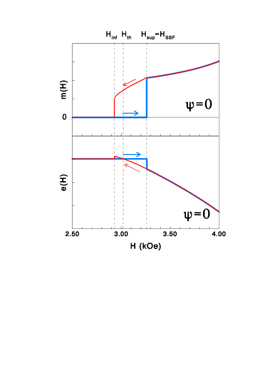
For applied in-plane parallel to the easy axis (), the calculation of the ground-state magnetization profiles shows that, in a limited field range near , the system admits two stationary configurations: the AF state, with collinear and antiparallel layer magnetizations, and the surface spin-flop (SSF) state, with a non-uniform magnetization profile characterized by a Bloch wall that nucleates near one of the film surfaces. In Fig. 1 we plot, in the neighborhood of , the field dependence of the reduced magnetization, , and of the reduced energy , given by Eq. (1). Using for the calculations kOe, kOe, and , the field of thermodynamic equivalence between the AF and the SSF state is found to be kOe, while the boundaries of the metastability region are given by the fields kOe and kOe. The AF state is the ground state for and is metastable for , while the SSF state is the ground state for and is metastable for . The calculated value of the bulk SF field is kOe.
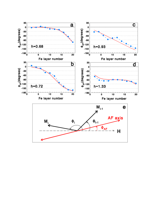
In Figs. 2,a-d the calculated ground-state magnetization profiles are compared with those obtained from polarized neutron reflectivity measurements, as published in Ref. tevelthuis, , at different field values, ranging between 0 and 5.5 kOe. The fields were scaled with respect to the bulk SF field, where we set kOe for the theoretical results and kOe for the experimental ones. The orientation of the antiferromagnetic axis (i.e., the axis along which the magnetizations of two Fe adjacent layers are antiparallel) is plotted as a function of the Fe layer number for selected values of the applied field. Figure 2e illustrates that , where is the angle formed by the magnetization of the -th Fe layer with the field direction. As the measured spectrum extends only as far as the half order AF Bragg peak, which is determined by the antiparallel components of the magnetizations, the orientation of the AF axis is obtained with more accuracy from the experiments than that of the individual layer orientations, for which the estimated error is up to 20o.tevelthuis This representation clearly depicts the position and extent of the domain wall for the different fields and shows that agreement between theory and experiment is fairly good.
From Figs. 2,a-d one sees that the basic features of the SSF transition in this film, characterized by a low value of , are the following: i) for the deviations from the uniform AF spin configuration originate just at the surface layer whose magnetization is antiparallel to the field; ii) with increasing , the surface-nucleated domain wall is pushed gradually into the middle of the film; iii) for a symmetric spin configuration is achieved, similar to the bulk SF one in the middle planes (while the spins at the surfaces, owing to the cuts of the exchange bonds, are less deviated from the field direction with respect to the bulk ones). Although not directly obvious from Fig. 2, the discommensurationmicheletti at the center of the surface-nucleated domain wall, effectively dividing the AF order into two antiphase domains, which was strongly evidenced by the neutron data,tevelthuis is also reproduced by the calculations.
Note that no abrupt variations of the magnetization, except the one at , are found as the field intensity is increased, see Fig. 1: i.e., additional first-order transitions between C phases, intermediate between the AF and the SSF one,rbarxiv ; mapchaos are not allowed by the low value of in this system.
III.3 Spin configuration for H applied along an arbitrary direction ()
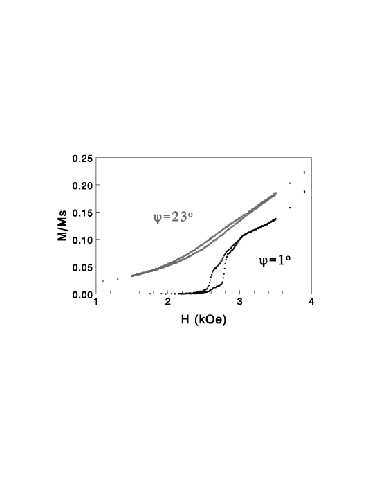
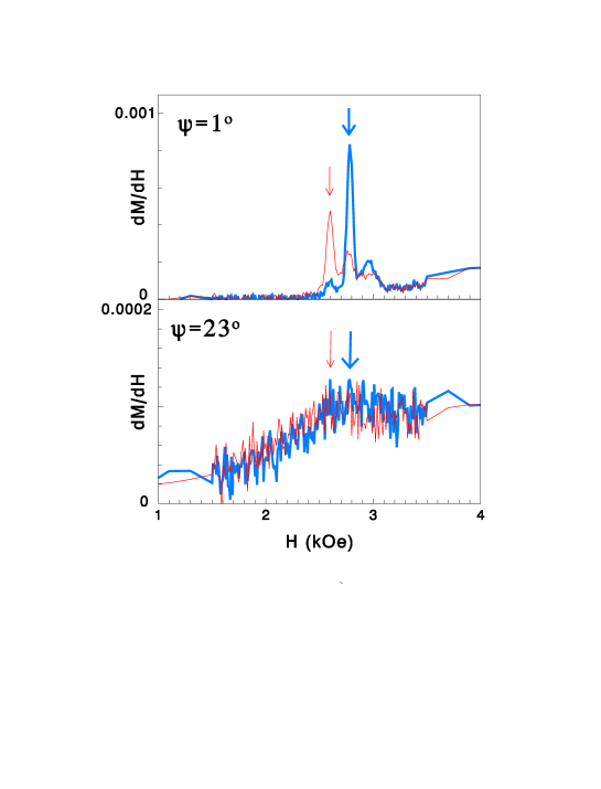
For a field applied in-plane along an arbitrary direction forming a skew angle with the easy axis (i.e., both and are non zero), one has that for . For , increases slowly with increasing , since for the magnetizations of the two sublattices are no longer compensated. Upon further increasing , a finite jump, signaling the onset of a first-order phase transition, was observed for a -dependent field value. The measurements were performed both upon increasing and decreasing and showed a marked hysteresis for such small values: see Fig. 3. The magnetic susceptibility , obtained by numerically deriving the measured magnetization with respect to , showed sharp peaks corresponding to the jumps in : see Fig. 4, top. The full width at half maximum (FWHM, see later Fig. 5, top) of the measured susceptibility peak was found to be constant and very small (essentially determined by the instrumental resolution), signaling that for such small angle values () the SSF transition is of first order.
As was gradually increased above 5o, became smoother (see Fig. 3), and the peak in (see Fig. 4, bottom) decreased in intensity, while the FWHM dramatically increased on passing from to , as shown in Fig. 5, top. The latter feature strongly suggests that a crossover of the surface phase transition from first-order to second-order might take place for .
In the light of this interpretation, it is however necessary to justify the persistence - up to the highest investigated value of (23o) - of a small hysteresis loop: see Fig. 5, bottom, where the measured dependence of the peak position of the magnetic susceptibility is shown as a function of the skew angle , both for increasing (full circles) and decreasing (open circles) magnetic field.
To this aim, we observe that the coexistence of first- and second-order transition features was recently observedli in single-crystal La0.73Ca0.27MnO3 perovskites exhibiting colossal magnetoresistance. The magnetization isotherms displayed a metamagnetic structure linked with a first-order transition, while field and temperature dependent susceptibility data presented a crossover line characteristic of a continuous transition.li
In our case of a finite AF Fe/Cr(211) film, a similar effect, i.e. the coexistence of first- and second- order transition features, might be attributed to a distribution of values of the interlayer exchange, as well as of the anisotropy of the different layers in the stack, due to the presence of thickness fluctuations. In determining the observed small hysteresis loop, one cannot either rule out the role of defects (pinning centers) which inhibit the lateral motion of domains during the magnetization reversal process.
In the following we will test if the experimental data can be explained in terms of a crossover from first- to second-order critical behavior by performing a theoretical calculation of the magnetization profile for different values of and , using either of the two methods described in Sec. II. In the present case where , the map portrait is not chaotic and the two different methods give similar results. From the calculated spin configuration, one obtains , and , given by Eq. (1).
We find that for the system admits two stationary configurations: a nearly AF state and a SSF state. The first one is stable only for while the second one is stable only for . By we denote the field of thermodynamic equivalence at which the two states take the same energy. As increases, the width of the metastability region gradually reduces until, for , only one equilibrium configuration is found.
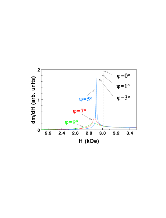
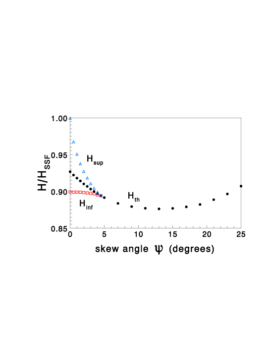
In Fig. 6 the calculated susceptibility is shown for different values of the skew angle . For , the peak in is a Dirac delta function, so the peak position is indicated by a vertical line. For the peak has a finite width and a finite height. As increases, the peak broadens and its height decreases. For clarity’s sake, the peak position reported in Fig. 6 for corresponds to the calculated field of thermodynamic equivalence between the energies of the AF-like configuration and the non-uniform SSF configuration. It is just the position of this peak that is reported vs in Fig. 7 as the full-circle diagram; the other two diagrams plotted for represent the calculated field values (open squares) and (open triangles) vs .
In the phase diagram of Fig. 7 one clearly observes that, upon increasing , the width of the metastability region gradually shrinks until, for greater than a critical value (film)=4.75o, the film admits only one equilibrium state. Thus, for (film) we expect the SSF transition to become continuous. The calculated value of (film)=4.75o turns out to be in remarkable agreement with the value estimated from the experimental results on the basis of the strong increase observed in the FWHM of . This fact provides support for the hypothesis of a crossover from first- to second-order critical behavior for the SSF transition in a skew field.
The calculated value of (film)=4.75o should also be compared with its bulk counterpart. In the bulk case, the field-induced phase transition of a uniaxial antiferromagnet in the presence of a skew field forming an angle with the easy axis was theoretically studied by Rohrer and Thomas.rohrer They predicted the first-order bulk SF transition to become continuous for (bulk)=. However, in MnF2, where , the critical angle turns out to be as small as . In the case of the Fe/Cr superlattice under study, the ratio is nearly an order of magnitude higher than in MnF2, so that an appreciable critical angle (bulk) is estimated. The calculated value of (film)=4.75o is nearly twice the bulk value. This can be qualitatively understood considering that, for not too high values of , in the bulk the critical angle is essentially determined by the ratio , while in the film the effective exchange field at the surface is halved with respect to the bulk.
IV Discussion
In this work we have investigated the transition, induced by a magnetic field with arbitrary direction, between the antiferromagnetic phase and the surface spin-flop phase of an epitaxial Fe/Cr(211) superlattice with Å, Å and repetitions. The system is characterized by a rather small value () of the ratio between the uniaxial anisotropy field and the exchange field , yet much greater than the value () pertinent to usual bulk antiferromagnets like MnF2 and Cr2O3.
For an external field applied parallel to the easy in-plane axis (), the layer-by-layer spin configurations measured by polarized neutron reflectometry were found to be in remarkable agreement with theoretical calculations, performed in the framework of a mean-field 1D model of the superlattice stack.
For a field applied in-plane along an arbitrary direction forming a skew angle with the easy axis, the superlattice magnetization was measured using magnetometry. The phase diagram of the film was calculated in order to check the possibility of a crossover of the surface phase transition from first- to second-order to take place for (film), similarly to what was predicted decades ago by Rohrer and Thomasrohrer for an AF bulk system in a skew field. Indeed we calculated (film), to be compared with the experimental value, , at which the jump in starts smoothening and the FWHM of the measured magnetic susceptibility displays a dramatic increase with increasing . Owing to the cut of exchange bonds at the film surfaces, the calculated value of (film) turns out to be nearly twice its bulk counterpart, (bulk).rohrer The latter value is much higher than the ones predicted for ordinary bulk antiferromagnets (e.g., (bulk) for MnF2 and for Cr2O3).rohrer
From the comparison between our experimental and theoretical results we conclude that a crossover between first- and second-order critical behavior is easier to be observed by magnetization measurements in Fe/Cr superlattices, thanks to the much higher value of the ratio between the anisotropy and the exchange fields in such an artificially grown system with respect to ordinary bulk antiferromagnets.
The interpretation of the experimental data proposed above needs, however, further investigation to be conclusive. In particular, a quantification of the magnetic domain structure in the presence of a structurally rough interface is required. While our previously publishedtevelthuis polarized neutron reflectometry data proved unambiguously that only one type of domains is present in Fe/Cr(211) superlattices with an interfacial roughness of Å for zero field, such a clear-cut evidence is lacking in the case of a nonzero field, applied in plane along an arbitrary direction. In conclusion, while we do not claim a quantitative accuracy for our theoretical results, nevertheless we believe that the main features of the spin-flop transition in the Fe/Cr superlattice have been captured by our ”ideal” model (i.e., characterized by structurally smooth and uniformly magnetized layers).
Acknowledgements.
Financial support from the Italian Ministery for University and Research is acknowledged. This work was performed in the framework of the joint CNR-MIUR programme (legge 16/10/2000, Fondo FISR) and of the COFIN Project on Magnetic Multilayers. The work at Argonne National Laboratory was supported by the US Department of Energy, Office of Science, under contract W-31-109-ENG-38.References
- (1) L. Néel, Ann. Phys. (Paris) 5, 232 (1936).
- (2) F. B. Anderson and H. B. Callen, Phys. Rev. 136, A1068 (1964).
- (3) D. L. Mills, Phys. Rev. Lett. 20, 18 (1968); W. Saslow and D. L. Mills, Phys. Rev. 171, 488 (1968).
- (4) F. Keffer and H. Chow, Phys. Rev. Lett. 31, 1061 (1973).
- (5) L. Trallori, P. Politi, A. Rettori, M. G. Pini, and J. Villain, Phys. Rev. Lett. 72, 1925 (1994).
- (6) L. Trallori, M. G. Pini, A. Rettori, M. Macciò, and P. Politi, Int. J. Mod. Phys. B 10, 1935 (1996).
- (7) V. L. Pokrovsky and N. A. Sinitsyn, private communication (2002).
- (8) E. E. Fullerton, M. J. Conover, J. E. Mattson, C. H. Sowers, and S. D. Bader, Phys. Rev. B 48, 15755 (1993).
- (9) R.W. Wang, D. L. Mills, E. E. Fullerton, J. E. Mattson, and S. D. Bader, Phys. Rev. Lett. 72, 920 (1994).
- (10) R. W. Wang and D. L. Mills, Phys. Rev. B 50, 3931 (1994).
- (11) L. Trallori, P. Politi, A. Rettori, M. G. Pini, and J. Villain, J. Phys.: Condens. Matter 7, L451 (1995).
- (12) C. Micheletti, R. B. Griffiths, and J. M. Yeomans, J. Phys. A 30, L233 (1997); Phys. Rev. B 59, 6239 (1999).
- (13) L. Trallori, Phys. Rev. B 57, 5923 (1998).
- (14) A. L. Dantas and A. S. Carrico, Phys. Rev. B 59, 1223 (1999).
- (15) S. G. E. te Velthuis, J. S. Jiang, S. D. Bader, and G. P. Felcher, Phys. Rev. Lett. 89, 127203 (2002).
- (16) A. N. Bogdanov and U. K. Rößler, Phys. Rev. B 68, 012407 (2003).
- (17) U. K. Rößler and A. N. Bogdanov, Phys. Rev. B 69, 094405 (2004).
- (18) U. K. Rößler and A. N. Bogdanov, Phys. Rev. B 69, 184420 (2004).
- (19) U. K. Rößler and A. N. Bogdanov, Phys. Status Solidi C 1, 3297 (2004) (Proceedings of the Second Seeheim Conference on Magnetism, special issue). We note that for the relationship between their notations and ours is the following: and , so that the ratio corresponds to in the phase diagram of the film (e.g. reported in Fig. 6 of their preprint for the case ).
- (20) H. Rohrer and H. Thomas, J. Appl. Phys. 40 (1969) 1025.
- (21) M. E. Fisher and D. R. Nelson, Phys. Rev. Lett. 32, 1350 (1974).
- (22) J. M. Kosterlitz, D. R. Nelson, and M. E. Fisher, Phys. Rev. B 13, 412 (1976).
- (23) K. W. Blazey, H. Rohrer, and R. Webster, Phys. Rev. B 4, 2287 (1977).
- (24) R. A. Butera, L. M. Corliss, J. M. Hastings, R. Thomas, and D. Mukamel, Phys. Rev. B 24, 1244 (1981).
- (25) J. W. Lynn, P. Heller and N. A. Lurie, Phys. Rev. B 16, 5032 (1977).
- (26) J. A. J. Bastee, E. Frikkee, and W. J. M. de Jonge, Phys. Rev. B 22, 1429 (1980).
- (27) L. D. Landau and E. Lifshitz, Physik. Z. Sowietunion 8, 153 169 (1935).
- (28) R. Pandit and M. Wortis, Phys. Rev. B 25, 3226 (1982).
- (29) K. E. Kürten and F. V. Kusmartsev, Phys. Rev. B 72, 014433 (2005).
- (30) H. Holtschneider, W. Selke, and R. Leidl, Phys. Rev. B 72, 064443 (2005).
- (31) Wei Li, H. P. Kunkel, X. Z. Zhou, Gwyn Williams, Y. Mukovskii, and D. Shulyatev, J. Phys.: Condens. Matter 16, L109 (2004).