Excitation of surface plasmon-polaritons in metal films with
double
periodic modulation: anomalous optical effects
Abstract
We perform a thorough theoretical analysis of resonance effects when an arbitrarily polarized plane monochromatic wave is incident onto a double periodically modulated metal film sandwiched by two different transparent media. The proposed theory offers a generalization of the theory that had been build in our recent papers for the simplest case of one-dimensional structures to two-dimensional ones. A special emphasis is placed on the films with the modulation caused by cylindrical inclusions, hence, the results obtained are applicable to the films used in the experiments. We discuss a spectral composition of modulated films and highlight the principal role of “resonance” and “coupling” modulation harmonics. All the originating multiple resonances are examined in detail. The transformation coefficients corresponding to different diffraction orders are investigated in the vicinity of each resonance. We make a comparison between our theory and recent experiments concerning enhanced light transmittance (ELT) and show the ways of increasing the efficiency of these phenomena. In the appendix we demonstrate a close analogy between ELT effect and peculiarities of a forced motion of two coupled classical oscillators.
pacs:
42.25.-p, 73.20.Mf, 78.20.Ci, 78.20.BhI Introduction
It is exactly tangible advances in structuring metals on nanoscales that give rise to a grate amount of experimental and theoretical works in the field of plasmonics, which examine resonance optic effects caused by surface plasmon polaritons (SPPs) excitation in structured conducting or semiconducting mediaBook_Raether ; Book_Agranovich ; Zayats_Maradudin_2005 . These quasi two-dimensional (2D) electrodynamic objects have been thoroughly studied in the solid state physics, physics of surfaces and diffraction optics over the late few decadesEbbesen_Nature_03 . An SPPs are electromagnetic surface waves, coupled to the collective electron excitation, they attract a great deal of attention due to their unique possibility of light localization and essential enhancement of the electric field near the surface.
A considerable interest in SPPs stems from the latest experiments on ELT phenomena. Since 1998, after observation by Ebbesen et.al.Ebbesen98_Nature ; Ebbesen_PRB_98 the violation of Bethe’s approachBethe to the diffraction by subwavelength periodic hole arrays in real metal films, this has been the subject of many studies. Until the recent moment one of the most generally recognized explanations of the ELT through subwavelength periodic hole arrays is the excitation of SPPs. Most of the authors (especially theoreticians), who hold on to the SPP conception of ELT, assume that the field enhancement results from “interface” SPPs, being either single-boundary localized (which is a common case for a nonsymmetric dielectric surrounding of the film) or double-boundary localized for the symmetric surrounding. A periodic hole array plays a role of a coupler between the SPPs existing at the boundaries of the conducting film and the incident light. In this context the crucial point is the surface periodicity. The periodicity caused by other factors, such as corrugation or periodic modulation of the medium electromagnetic properties, etc., also result in the light-matter interaction resonance features, in particular, the ELT effect. Note that comparing the ELT transmittance peaks positions to those caused by SPP excitation in different diffraction orders undoubtedly points out a significant SPP role, see numerous experiments, e.g. Refs. Ebbesen98_Nature, ; Ebbesen_PRB_98, ; Ebbesen2001_Opt, ; Ebbesen_theory_PRL01, ; StrongCoupling_PRB05, ; shadows_APL_02, ; Fluorescence_OptLett_03, ; Barnes_PRB04, ; hole_depth_APL02, .
It should be noted that the observed ELT effects are strongly dependent upon the film surrounding. As the film having the subwavelength hole array is surrounded by the dielectrics with the same dielectric constants (for instance, a free-standing film) the excited SPPs are double-boundary-localized, that is, the field is enhanced at both faces of the film, see experimentsEbbesen2001_Opt ; Ebbesen_theory_PRL01 . In this geometry the ELT in zeroth diffraction order is much more pronounced as compared to the nonsymmetrical film surrounding, when the excited SPPs are single-boundary-localized, that is the field can be enhanced at a single face of the film. Generaly, this corresponds to the films deposited onto the quartz substrate. Both of these cases have been so far studied by using numerical methodsEbbesen_theory_PRL01 ; Ebbesen2001_Opt ; WoodHoles_PRB03 ; Popov_PRB00 ; shadows_APL_02 ; Book_Petit03 ; Zayats_PRL01 ; plasmonic_metamaterials_JOPA05 . It was also shown numerically and experimentally that the ELT occurs for periodical conducting structures without holes. Basically this is quite evident, since the type of periodicity does not play a crucial role for the excitation of the interface SPPs. These were chiefly the structures with relief corrugations of the film faces both for symmetricalBloch_mode_OSA04 and nonsymetricalGrating_couplers_99 ; Arutsky_OptLett_00 ; Nonzeroth_Barnes_APL_01 dielectric surrounding and the structures with periodically-located dielectric pillarsPopov2003_OptExpr .
Several authors have developed an analytical approach which qualitatively describes the ELT. They have studied the diffraction by the film with one-dimensional (1D) periodically modulated dielectric permittivityLightTunelling_PhysRev ; Dykhne_PRB_03 ; AnalyticalTheory_PhysRev ; Genchev_JETP04 ; Bliokh05 ; Franches_OptExpr05 . In these works a study has been made in the simplest case of a strictly normal incidence onto the symmetrically surrounded film with harmonic modulation of the film permittivity. The exception are the papers AnalyticalTheory_PhysRev ; Franches_OptExpr05 , where the theory is generalized to the nonsymmetric surrounding. The authors of these works have described the zeroth-order transmittance dependence upon the parameters in case of SPP excitation in the first diffraction order. In contrast to them, in a certain sense, we have provided a more general analytical insightOurs_JETPHL_04 ; film_PhysRev ; KNN_PhysRev , by solving the problem of vector diffraction by the film with nonsymmetric and symmetric dielectric surrounding for arbitrary modulation Fourier spectra of the permittivity of the metal at an arbitrary incident angle and at an arbitrary polarization of the incident light. The advantage of our analytical treatment is that we have described not only the first-order resonances, but have given a classification of the resonances corresponding to single or double-boundary-localized SPPs excitation in single or multiple diffraction orders. Also, we have examined a nonzeroth-order ELT that was observed in the experiments Refs. Nonzeroth_Barnes_APL_01, ; Korea_03, . Mention also paper LeePark_Nanoslits_PRB05 , where the alternative analytical approach was suggested to describe the light transmittance through metallic nanoslit structures.
Yet another important class of plasmonic structures possessing interesting diffraction resonance phenomena are metallic nanoparticle arraysGoldNanoparticlePlasmon_NANOL05 ; Nano_Chem_01 ; NaomiHalas_MRS05 ; Barnes_PRB04 . As known, they can support the so-called localized SPP resonances which are strongly dependent upon the shape of the individual particlesNaomiHalas_MRS05 . It is believed that the shape resonances similar to the localized ones, may affect the ELT in subwavelength hole arrays. The influence of the hole or/and nanoparticle shape was studied experimentally inLocalizedSPP_JOPA05 ; hole_shape_PRL04 ; shape_localized_PRB05 . The study of the conducting films containing periodic lattices of dielectric nanoparticles and voids have been made in Refs. Gang_Sun_2006, ; Kelf_2006, ; local_SPP_in_voids, . However, we are not aware of the study on the experimental or theoretical optical properties of metallic nanoparticle arrays immersed into a conducting film. Similarly to a nanohole array, such a nanoparticle array should display ELT with the wavelength spectra depending strongly upon the nanoparticle shape.
In the present paper we go on investigating the resonance optical effects by generalizing the earlier developed analytical treatmentfilm_PhysRev ; Ours_JETPHL_04 of the conducting films with 2D modulation. We consider the vector diffraction problem for periodically located metallic inclusions in the metal film with an arbitrary dielectric surrounding. Since the inclusions are presumed to be entirely imbedded into the film (the faces of the film being flat), the resonances of our system correspond to the excitation of purely interface SPPs, the localized-SPP resonances do not exist. Along with the fact that such structures are of interest by themselves, they may be considered as a model of subwavelength hole arrays; and the approach developed is appropriate for other periodical structures (say, for corrugated films). One more substantial aspect of our approach is that we can easily describe the polarization of light transmitted or/and reflected by the 2D periodical structure. The polarization properties of subwavelength hole arrays is also a matter of interest, and they have been intensively studied in recent yearsStrongPolariz_PRL04 ; PolarizControl_OptLett04 ; PolarizTomography_OptLett05 ; Opt.Depolariz_PRB05 ; terahertz_Appl.Opt._04 ; KNN_PhysRev .
The paper is arranged as follows. Following the Introduction, in Section II, we describe a general approach to the problem of resonance light diffraction by a 2D periodically-modulated conducting film for the conical mount case and for an arbitrary polarization of the incident light. We accentuate the fact that the form of the periodically-located inclusions have an impact upon the Fourier spectra of the periodical structure and this, in its turn, influences the excited SPPs considerably. In Section III we examine the excitation of single-boundary-localized SPPs in the nonsymmetrically-sandwiched film, considering both the entire transmittance and reflectance spectra and a more detailed analysis of different resonances in their close vicinity. We give an explanation of the recently observed polarization dependence upon the hole shapehole_shape_PRL04 from the view point of Fourier spectra of the periodical structure. Besides, we compare our calculations with other recent experiments. Section IV is devoted to the resonance effects caused by the excitation of double-boundary-localized SPPs in the symmetrically-sandwiched film. We study in detail the fine structure of the two-humped resonance maxima (minima) of the transmittance (reflectance), stressing the role of long-range and short-range SPPs. As far as we know, the fine structure of two-humped resonances corresponding to the symmetrically surrounded film has not been studied thoroughly in experiments. In the Appendix below we draw an analogy between the ELT and the forced oscillations of a well-known classical system of two weakly coupled linear damping mechanical oscillators.
The problem under consideration is of profound interest not only from the view point of a pure physics, but can find numerous applications in optical subwavelength devices designEbbesen_Nature_03 ; Plasmon_devices_05 . For instance, recently, SPP in sandwiched structures found itself as surface plasmon resonance optical sensors,Jiri_Homola_1999 ; Jiri_Homola_2003 ; Paul_V_Lambeck_2006 and some of them are already commercially available. These sensors are based on the interaction between waveguide and SPP modes. The basic feature of the sensors is measuring the refractive index variation in biological and chemical real-time high-definition sensing. It is important to mention that ELT phenomena are studied in the microwave (THz) region of electromagnetic waves ELT_microwave_JOPA05 ; THz_SPP_diploma03 ; terahertz_Appl.Opt._04 which attracts a great deal of attention.
II Problem statement and main equations
II.1 Analytical approach
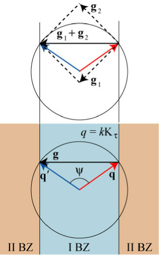
Consider an arbitrary polarized plane monochromatic wave with wave vector incident onto a surface of a double periodically modulated metal film surrounded by dielectric media with permittivities , , from the medium corresponding to . Imply that the periodicity is caused by modulation of the dielectric permittivity of a conductor, , , so that , are elementary translation vectors, see Fig. 1.

In what follows one has to deal with the Fourier expansion of the function , where is the mean value of the dielectric permittivity of the metal, . The expansion of this function over coincides in the zeroth order with the expansion of the surface impedance, , over the same parameter. Therefore, let us recall, for brevity, the function surface impedance. We write its Fourier representation as follows
| (1) |
where , is a vector index, or a multiindex, (integers , indicate a number of elementary translations along vectors of reciprocal grating, , ); the zero multiindex is . The electric fields in the dielectric media are written in the form of Rayleigh expansion [the time dependence is omitted everywhere]:
| (2) |
for if . Here is the film thickness, denotes the electric field amplitude of the incident wave, , tangential, , , and normal, , , components of the wave vectors of spatial field harmonics, , , are
| (3) |
where is an angle of incidence, . Analogously to film_PhysRev ; Ours_JETPHL_04 ; KNN_PhysRev we will take into account the modulation in the boundary conditions only, so that within the conducting film we seek the solution in the form
| (4) |
Introducing polarization unit vectors:
| (5) |
where correspond to () or () polarization for in th diffraction order in the dielectric media , and are polarization basis vectors for the incident wave. With respect to the polarization vectors, the electric and magnetic fields in the dielectric media are
| (6) |
where ; and analogously inside the film. Let us introduce the polarization transformation coefficients (TCs), , as
| (7) |
Then, excluding from the Maxwell equations and the boundary conditions the internal fields, we arrive at the following infinite linear system for the TCs corresponding to the outer fields
| (8) |
The matrix and the right-hand side vectors are linear with respect to the modulation,
| (9) |
The modulation-independent terms are diagonal both with respect to the diffraction order and polarization. Explicitly,
| (10) |
Here
| (11) |
the real part of is the film thickness in the skin-depths, is the dimensionless component of the th field harmonic wave vector, which is related with the coresponding tangential component as
| (12) |
The nondiagonal terms are
| (13) |
() are sines (cosines) of the angle between vectors , ,
| (14) |
The resonances in the system are due to existence of the eigenmodes in the film, i.e., SPPs. When an evanescent field harmonic is close to the grazing one, its amplitude increases significantly as the process of eigenmode excitation occurs. For infinitesimal modulation the eigenmodes of the film are initial SPPs, with the dispersion relation corresponding to the determinant of the matrix vanishing in zeroth order approximation in modulation. Then becomes an infinite product of determinants, so that each of them corresponds to some SPP eigenmode of the unmodulated film. The equation has the physical roots for only, that corresponds to polarization:
| (15) |
For a rather thick film, , SPPs existing in the film are close to those existing at the boundary between the metal and each of the dielectric half-spaces, and are single-boundary-localized (SB) SPPs. These modes are governed by the dispersion relation
| (16) |
where is for metal-substrate (superstrate) SB SPP. The symmetric surrounding (for instance, a free-standing film) presents a specific case because of the coincidence of the Eq. (16) solutions for different .111For a modulated film there can exist coupling between SB SPPs caused by diffraction. Such DB dressed SPPs correspond to specific relations between permittivities of the dielectric media. Formally they correspond to simultaneous vanishing of two determinants, and , with , and in calculating the matrix determinant (in the lowest order in the modulation) one has to take into consideration the products of the determinants of the diagonal in diffraction orders submatrices along with the terms corresponding to the submatrices , . Then the initial SPPs existing at the boundary of the metal and dielectric half-space become coupled due to the finite film thickness, and one obtains the two double-boundary-localized (DB) SPP modes: long-range (LR) and short-range (SR) SPPsLRSPP_PRB91 ; Surface-Polariton-Like_PRB86 . For , and, respectively, , one finds from Eq. (II.1) the two roots, ,
| (17) |
that is the single-boundary localized modes coupled into double-boundary localized ones. Therefore, the frequencies of initial SPPs are repulsed, the spectral degeneration vanishes, and one arrives at two different eigenfrequencies described by Eq. (17). Here superscript “” (“”) corresponds to the LR (SR) SPP. The LR (SR) mode possesses a high (low) frequency and is related to antisymmetric (symmetric) with respect to the midplane surface charge distribution and the spatial distribution of the tangential to the film faces electric field component. As a result, SR SPP possesses higher Ohmic losses.
Since the modulation is presumed to be small, the eigenmodes of the modulated film (“dressed” modes) differ slightly from those existing in the unmodulated film. The dispersion relation of the dressed SPP modes defines the resonance conditions. However for identification of the resonance type the modulation can be neglected. Bearing in mind that depends upon the angle of incidence, , and the wavelength, , it is possible to consider the imaginary part of (16) as the “resonance curve” in plane. For instance, in the case of rectangular symmetry, , , imaginary part of Eq. (16) reads
| (18) |
where is the angle of the incident plane orientation relative to (say, “tilting” angle), , and is the dimensionless wavevector of SPP. We designate the curve given by Eq. (18) as . All points of plane may be classified as follows. Indeed, the resonance curves possess the finite width due to the dissipative and radiative losses and, therefore, it is more appropriate to refer to the resonance vicinity, but not to the resonance point. If a point does not belong to any resonance curve, we have a nonresonance diffraction case. If a point belongs to a single curve with a fixed and , we obtain a single diffraction-order single-boundary resonance (SSB). If a point corresponds to intersection of several curves having different multiindexes , but the same value, we obtain a multiple diffraction-order single-boundary resonance. Note that for specific geometry of high symmetry, and , the curves for different signs of and coincide; when curves and are indistinguishable as well. Intersection of two resonance curves with different yields the point of a double-boundary resonance. When DB SPPs have a unique multiindex we then arrive at a single diffraction-order double-boundary resonance (SDB). SDB resonance occurs only for the symmetric surrounding of the film, . Here the initial surface modes are coupled mainly through the finite film thickness and, in general, the corresponding dependencies of the reflectance/transmittance are of two-valley (two-peak) shape due to splitting of LR and SR modes. The explicit form of the resonance curve corresponding to LR (SR) SPP resonances coincides with that given by Eq. (18), if one changes to [] in the designation of in Eq. (18). When DB SPPs are related to different multiindexes (multiple diffraction-order double-boundary resonance), which occurs under very specific conditions, they are coupled through periodicity and the finite film thickness simultaneously.
Now take up the solution of the system (8). In a small region of plane, which is of order of the resonance width, the solution is strongly dependent upon the number of resonance curves passing through this region. Hence it is convenient to subdivide the set of the diffraction orders into a resonance subset, , which contains the multiindexes relative to the above-mentioned curves, and a nonresonance subset, . Thus, we subdivide the initial infinite system into the resonance subsystem containing the resonance TCs and the nonresonance subsystem containing the nonresonance TCs. The resonance TCs correspond to -components of the TCs with the resonance multiindexes, and the nonresonance TCs correspond to -components of amplitudes with the resonance multiindexes, , and both - and -components of TCs with nonresonance multiindexes, , .
In the main approximationOurs_JETPHL_04 ; film_PhysRev ; KNN_PhysRev , which assumes retaining the quadratic in modulation amplitude terms in the matrix elements, and the linear terms in the right-hand sides, the resonance subsystem becomes:
| (19) |
where
| (20) |
| (21) |
Here , the sum with the overline, , means that the terms with the superscript and a resonance diffraction order have to be omitted. The function is equal to , if within the resonance indexes there is the zeroth one, and to otherwise. The zero-value of matrix determinant yields a dispersion relation of the SPP modes in the film in the main approximation. As was discussed above, the block, , being diagonal relative to the diffraction order, contributes to the unperturbed dispersion relation. The nondiagonal, linear-in-modulation block, , contains the “interresonance” or “coupling” modulation harmonic, , which is chiefly responsible for the SPP dispersion curve splitting, and for the appearance of the spectral band gapSPIE ; Maradud_2D_gaps_PRB02 . The third term in (II.1) is quadratic in modulation, and describes the second-order scattering processes which provide the broadening and the shift of the dispersion branches.
The nonresonance TCs, , are expressed in terms of the resonance TCs as
| (22) |
is a transmission (for ) or a reflection (for ) coefficient corresponding to (for ) or (for ) polarization in the case of an unmodulated film. -components of the TCs with the resonance multiindexes, , are expressed in terms of -components, , and are small as compared with the latter; they are of no interest, and we do not present them herein. The diffraction efficiencies are
From the energy conservation it evidently follows that
| (23) |
where is the absorbed part of the energy flux density.
II.2 Single diffraction-order resonance
If a sertain point of plane belongs to one or two curves (18) having a single multiindex (for other parameters being fixed) the vicinity of this point defines a single diffraction-order resonance. Moreover, according to the above classification, in the case of one curve (for a single ), we have a SB resonance, and if the point is the intersection of two curves with different values, we have a DB resonance. The resonance TCs are then similar to those obtained for 1D modulation, cf. Ref. KNN_PhysRev, ,
| (24) |
where
| (25) |
| (26) |
| (27) |
| (28) |
Stress that , . The resonance TCs have two poles. For a nonsymmetric surrounding, these poles are releted to SPPs existing at the opposite film faces, while in the case of a symmetric surrounding, they are related to LR and SR SPP modes.
The structure of the resonance TCs indicates that the coupling strength between the incident wave and the SPP excited is proportional to the scalar product of the SPP and the incident wave magnetic fields. Note that the SPP magnetic field is orthogonal to its propagation direction and is parallel to the interface so that the SPP is effectively excited by the projection of the tangential component of incident wave magnetic field onto (or, alternatively, by the scalar product of tangential components of the electric SPP fields and the incident wave). As for ()-polarization of the incident light, the projection is (), where is the angle between and . For instance, with the incidence of purely - (-) polarized light, the SPPs propagating parallel (perpendicular) to the incidence plane cannot be excited, even if wavevector is close to the poles in Eq. (24).
The zeroth-order polarization matrix is
| (29) |
where
| (30) |
is the angle of propagation of the zeroth-order wave in th dielectric media relative to axis (in the superstrate ). The structure of these coefficients shows an interference caused by the competition between the nonresonance channel (the terms ), and the resonance channel (the second terms in Eq. (II.2), which is proportional to ). The nonresonance term should be retained for the zeroth-order reflectance, since it is of order of unity, , while for a rather strong resonance it can be neglected for the transmittance in the vicinity of the resonance maxima, since and is much smaller than the resonance input into the transmittance.
The wavelength resonance width, , is contributed both from the dissipation losses, being proportional to , and from the radiation losses due to SPP scattering into the outgoing propagating waves. It is of order , as it follows from (24)-(II.2). The term proportional to is caused by the radiation losses and in the simplest case may be represented approximately as , where , and the summation is performed over those that satisfy . According to the formulas describing the resonance and zeroth-order TCs, the optimal amplitude of the resonance harmonic is and this leads to the resonance width of order . The optimal amplitude is related to the maximal SPP excitation and, consequently, to minimal/maximal value of reflectance/transmittance. In spite of the fact that we assume the modulation to be rather small, let us make a rough astimation of the resonance width for the hole arrays. For Ag films in the visible and near infra-red frequency region the impedance of the film is , while for the holes the impedance . Therefore, , and . For wavelength of order the resonance width can be estimated as , which is in good qualitative agreement with numerous experimental results. In the experiments the resonance width is equally affected by the non-plane character of an input light wave and the finiteness of the periodic array.
Note that the resonance width is very important for problems of sub-diffraction-limited optical imaging (optics of volume or surface “superlenses”). Sufficiently broadened SPP resonances may be efficiently used to enhance the evanescent modes and thus to recover the subwavelength information on nanoobjects, see Ref. superlens_science05, .
II.3 Multiple resonances
The approach developed allows one to consider the diffraction problem for the resonances of arbitrary multiplicity on 2D-periodical structures possessing an arbitrary symmetry. But from the experimental point of view the resonances of fourfold multiplicity, which take place for the normal incidence, , at the square and rectangular periodical arrays are of special interest. Here, and in what follows, we will concentrate on the structures possessing symmetry: ; the geometrical symmetry (Brillouin zone symmetry) is supposed to be , i.e. is perpendicular to and their modules are equal, . As it seen from Eq. (18), at normal incidence the multiple SPP resonances arise at the wavelengths , where is the period of the structure. Points , in the plane are the intersections of four resonance curves for the single (SB resonance) or eight curves for both (DB resonance in symmetric surrounding). We mark a fourfold SB resonance as , which corresponds to the intersection of the following resonance curves: , , , and . A fourfold DB resonance is marked as respectively. In addition, if all values of a certain function with subscripts from the above subsets are equal, we denote it by .
Similarly to the single resonance, when we have the fourfold one, the pair of field harmonics with wavevectors and is efficiently generated by the projection of the incident wave magnetic field onto the direction perpendicular to (the direction, corresponding to the SPP magnetic field with this wavevector), viz. by , where is the angle between and . Analogously, the amplitudes of the field harmonics corresponding to diffraction indexes are proportional to . Thus, for special polarization of the incident wave, at , th the resonance field harmonics are not excited via the first-order scattering process (but rather via the higher-order processes). This reduces the multiplicity of the resonance twice in the main approximation. For an arbitrary polarized incident wave, the polarizations of the zeroth-order transmitted and reflected waves are formed mainly by the interference contribution of all resonance field harmonics due to single back-scattering. Also, they are contributed from the zeroth-order components related to the “scatteringless” reflection and transmission for an unmodulated film. Otherwise, the polarizations of both propagating and evanescent nonresonance field harmonics are formed mainly by the single scattering from the zeroth diffraction order and from all the resonance diffraction orders.
For the structures possessing modulation symmetry, the solution of (19) is considerably simplified in the vicinity of normal incidence. In the case of or resonance, the resonance TCs are similar to those given in Eq. (24), cf. explicit expressions in Appendix B, Eq. (B). Though in a linear-in-modulation term, , arises, which is the inter-resonance harmonic responsible for the splitting and shifting of the resonance.
To get a better understanding of the resonance diffraction, consider the eigenmodes of structures. They are defined approximately by relation . In particular, the eigenfrequencies may be found from equation . For SB-localized SPPs when we have a rather thick film, , the structure of eigenmodes can be obtained in the approximation of the half-space problem, see the detailed analytical treatment in Ref. SPIE, . Thus, we restrict ourselves to the eigenmodes that are close to those corresponding to the metal-dielectric interface and not coupled through film thickness. Bearing in mind the homogeneous problem setup, we must change the notations so that one of the resonance -vectors in the diffraction problem, , become the SPP quasi-wavevector, , ending in some Brillouin zone. The other wavevectors close to the resonance conditions correspond to the “resonance satellites”, that compose a coupled SPP state.
Concentrate first on the simplest case of a twofold coupling through the periodicity. Suppose that the resonance wavevectors are and . Then we can consider the diagonal in homogeneous subsystems of the resonance system (19) which contains the two TCs, for the diffraction orders and . Using Eqs. (II.1)-(14) (and assuming ), we write it as
| (31) |
Here , and we neglect the quadratic-in-modulation amplitude terms, supposing that they do not exceed the linear-in-coupling harmonic term. We take into account that in the th dielectric half-space the SPP electric field has predominantly a -component and therefore, change to . From this system we see immediately that the initial SPPs with wave vectors oriented at are not coupled, and it is thus the case where it is necessary to retain the quadratic coupling terms222In case of the periodicity formed by the surface relief corrugation, the situation changes principally: coupling does exist even when SPPs propagate perpendicular to one another.. Note that, as we see, here the problem is reduced to the one, corresponding to the twofold SPP coupling through the harmonic grating of the period (and with amplitude ), where the quasi-wavevector of the dressed SPP, , and the satellite, , refer to the sides of a Brillouin zone, see Fig. 2. Then , where , and the dispersion relation becomes
| (32) |
Remind that is the angle between and . Hence, we obtain the two roots: the first one is for the high frequency mode, , and the second one is for the low-frequency mode, . Specifically, neglecting the modulation of the small real part of the surface impedance as compared with that of its imaginary part we have , and . Hence, the eigenfrequencies are
| (33) |
where the upper (lower) sign is for high (low) frequency SPP. It is important to note that the quality()-factor for the high-frequency mode is higher than that for the low-frequency mode.
For the specific choice of coordinate origin, such that , , the electric field amplitudes of the eigenmodes obey the relation . As the coupled SPPs propagate in the opposite directions, , we have , and the field structure at the interface for the eigenmodes is
| (34) |
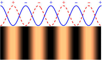
Note that under the condition of the prevalence of the coupling in the first order scattering, or, in other words, when the coupling harmonic dominates over the others, , the structure of the spatial field distribution is given by the coupling harmonic. In other words, the field maxima of the high frequency mode coincide with the “less metallic” regions (where is higher) relative to the coupling harmonic and vice versa for the low frequency mode, see Fig. 3.
Discuss the eigenmodes for fourfold SB SPP resonance. We limit ourselves to resonance, such that , , and . Remind that the resonance amplitudes corresponding to perpendicularly oriented vectors are not coupled in the first scattering order. One can make sure that four eigenmodes exist. Two of them are “mixed”, that is, all resonance amplitudes are nonzero: , moreover, , and . Thus, the field structure has the form of the linear combination of two cosines having their periods along and . These modes cannot be excited at normal incidence. Other two modes, which may be excited, have zero resonance amplitudes: for one mode , , and , for another one. Consequently, the spatial structure corresponds to sinuses. Thus, the structure of the eigenmodes in this particular instance of fourfold SB SPP resonance is similar to that of twofold SB SPP resonances; they have the form of a pair of standing SPPs, that correspond to the sinus-type spatial field distribution, and higher-frequency (and also higher Q-factor) branches. This means that in Eqs. (II.3) taking “” we should set , , and the first (second) standing SPP quasi-wavevector, , becomes parallel to [].
The solution of the inhomogeneous problem is the superposition of the above standing SPPs with the “weights” proportional to cosines of the angles between , , and . The eigenmodes for other SB-fourfold resonances may be treated in a similar way, they are the combinations of simplest SPP modes as well.
For DB-localized dressed SPPs the field structure is defined by coupling of the initial SPPs both through the modulation and through the finite film thickness. The field structure resulting from the coupling through the film thickness may be understood from the example of the undressed SPP existing in the unmodulated film. The eigenfrequencies for this case are defined by Eq. (17). Note that inside the metal the amplitude of the tangential-to-interface component of the electric field is higher than -component, , in contrast to the dielectric half-spaces. Remind also that -dependence of the electric field inside the film for LR and SR eigenmodes isBook_Raether ; Book_Agranovich
| (35) |
where stands for LR SPP and for SR SPP.
For dressed DB-localized SPPs with the twofold coupling, the dispersion relation is
| (36) |
where , , superscripts in brackets mark the eigenmodes. Here the initial SPPs (and corresponding diffraction indexes) are the same as in the above case of the dressed twofold SB SPP. The spatial field distribution for eigenmodes inside the film for () has the form
| (37) |
-components of the electric field in the dielectrics at the film faces are of the same form as in Eq. (34), i.e. and . It is possible to obtain the eigenfrequencies and the field structure for the fourfold DB SPP, proceeding in the same way, in which we generalized the twofold SB SPP to the fourfold SB SPP.
Analyzing the denominator of TCs, on can make sure that the excited DB SPPs are related to “” modes only. Indeed, with the film thickness tending to infinity, we can see that the two poles of TCs in Eq. (B) of Appendix B, , become , in neglecting the second-order scattering processes. Choosing an origin such that , the poles coincides with “” branch of Eq. (32), where we have instead of , and . This corresponds to the upper frequency branch, Eq. (II.3), and, hence, to the “sine” field distribution in the plane.
Under the assumption of modulation symmetry the zeroth-order TCs for SB resonance have similar to Eq. (II.2) structure as well (see Appendix B). However, the difference consists in identity , which ensures that the polarization of the zeroth-order transmitted wave coincides with that of the incident wave.
Along with the anomalies related to SPP excitation there exist Rayleigh anomalies. They correspond to the boundary between homogeneous (propagating) and inhomogeneous (evanescent) waves in different diffraction orders, viz to the vanishing of -component of one of the wave-vectors, , or . From the mathematical point of view, the Rayleigh anomalies are the branch points; they set the conditions for the breaking of the incident angle or wavelength derivative of the transformation coefficients. In what follows we will mark the Rayleigh anomalies as (which corresponds to the vanishing of ) or as (which corresponds to the vanishing of ).
Since modulation harmonics play a crucial role in SPP excitation, et us consider below the Fourier representation of the structures predominantly used in the experiments.
II.4 The modulation spectra
The majority of experimental works deal with hole arrays fabricated with the use of metal films deposited onto a dielectric substrate (predominantly onto quartz), see Fig. 1. Instead of holes we will consider a cylindrical inclusions in the film. The inclusions are supposed to consist of a metal or a semiconductor with the dielectric permittivity different from the permittivity of the film. Both the inclusions and the film must be highly conducting. This structure, as we will see below, may qualitatively describe the optical properties of nanohole arrays, even thought the film does not contain holes as such. Furthermore, the results from our studies may be used for modeling and describing arrays of cylindric nanoparticles, so far examined experimentally. Indeed, the structure considered may be fabricated by making an array of cylindric nanoparticles with impedance , which are immerged into a conducting film.
For the inclusions of a round cross-section with radius , we have
| (38) |
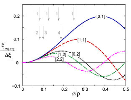
where is the difference between film (), and inclusion () surface impedance, is the first-order Bessel function. A typical example for the Fourier spectrum of the array of cylindrical inclusions for the square symmetry structure is shown in Fig 4. The square symmetry structure means, that the angle between translation vectors is and their modules are equal, . In the following calculations we take to be equal to the impedance of (using the wavelength dependence from Ref. Book_Zolotarev84, ); the impedance of inclusions will be modeled as , where is the dimensionless parameter.
As evident from Eq. (24), the amplitude of the resonance (th) diffraction order is proportional to , , therefore, the efficiency of excitation of SPP in this order is strongly dependent upon the corresponding “resonance” amplitude . For large values of the Fourier amplitude tends to zero as
| (39) |
Thus, the resonances in high diffraction orders are less efficient. If the inclusion diameter is far smaller than the modulation periods, the low-order amplitudes are approximately independent of their order:
| (40) |
So, for very thin inclusions the Fourier amplitudes of the structure show a slight decrease, which is valid for an arbitrary cross-section of the inclusions. In its turn, it significantly broadens the SPP resonances: they become “diffusive” due to different scattering processes of the excited SPPs.
Let us write also the Fourier expansion of the structure having the inclusions of a rectangular cross-section,
| (41) |
where are the vectors oriented along the sides of the rectangular inclusions with modulus equal to their lengthes, .
III SB SPP resonances. Nonsymmetric surrounding
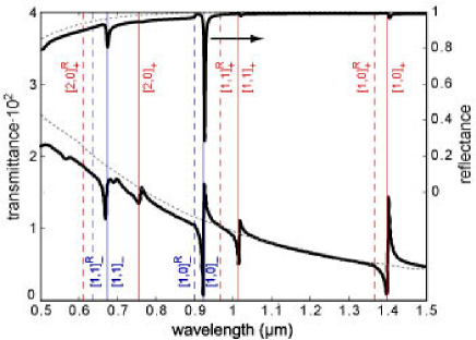
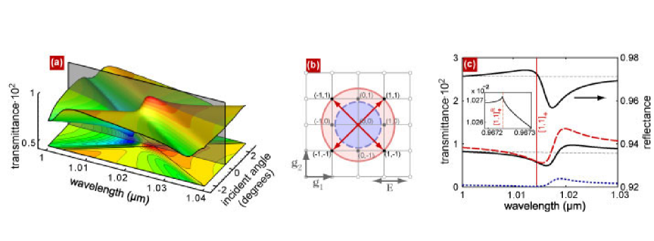
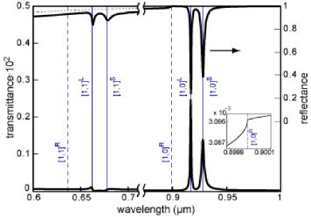
Bearing in mind the experiments already made, periodically-modulated films surrounded by two different dielectric media are of special interest. These structures can support both SB-localized SPPs and, under the special conditions, DB-localized SPPs. The latter will be discussed separately. In the vicinity of normal incidence we mainly focus on, the resonances basically correspond to SB-localized SPPs. An example of the transmittance and reflectance wavelength spectra for the strictly normal incidence is illustrated in Fig. 5. The calculations are for array of inclusions with a round cross-section in the Ag film surrounded by air superstrate and quartz substrate. The transmittance and reflectance extremes are pronounced at wavelengths for the SPPs existing on unmodulated metal-quarts and metal-air interfaces. Note that while the extremes are shifted with respect to initial SPPs wavelength, wich is due to the modulation and finite film thickness influence, Rayleigh anomalies are unshifted.
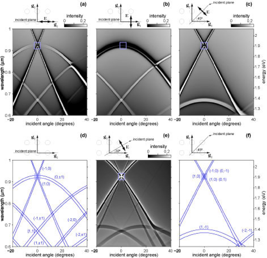
Now discuss the vicinity of the strictly normal incidence. In Figs. 6 (a-c) and (e) the transmittance contour plot is shown as a function of the wavelength or/and photon energy and the incident angle for different polarization of the incident wave. In Fig. 6 (d,f) the resonance curves (18) corresponding to the contour plots in Fig. 6 (a-c) are presented.
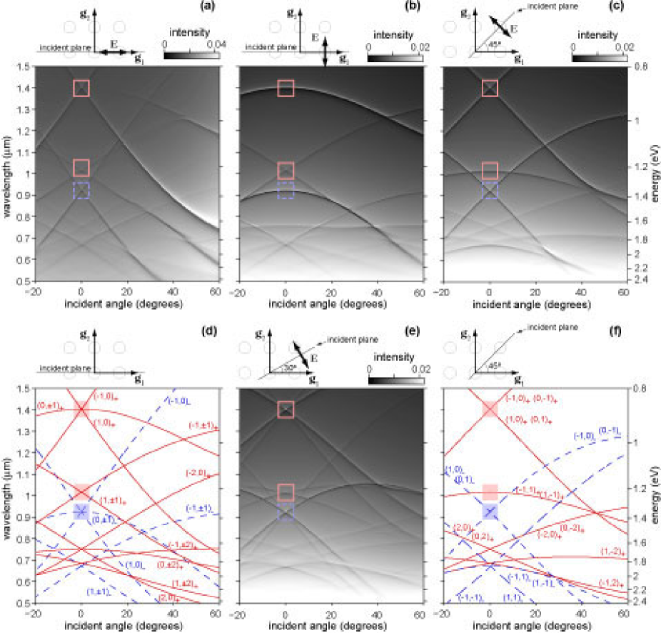
There is an excellent agreement between the transmittance features and the resonance curves. It should be stressed that the short-wavelength region corresponds to strong dispersion, . In Figs. 6 (a-c) the special symmetry instances are shown. Viz., orientation of the incident plane relative to one of the reciprocal grating vectors (in our case it is ) at angles (or ) and results in the coincidence of the resonance curves, see discussion below formula (18). The coincidence is appreciable in the vicinity of , and resonances. In Fig. 6 these vicinities are marked by squares. We see that in Figs. 6 (a-c) from one to three resonance features belong to these regions. Evidently, in Figs. 6 (d,f) from one to three resonance curves resonance intersect these regions. Alternatively, four resonance “mountain ridges” intersect in the vicinity of a single point, see Fig. 6 (e), which displays the transmittance contour plot for the nonspecific in the angle case.
Emphasize, that the intersections of solid and dashed resonance curves in Figs. 6 (d,f) and the intersections of corresponding resonance “mountain ridges” in the transmittance contour plots are due to DB SPP resonances. The latter comply with the excitation of dressed SPPs, resulting from the coupling of initial SPPs of different film faces through the modulation.
In the following subsections we examine in detail some of SB fourfold resonances.
III.1 resonance
Consider first the longest-wavelength resonance (at 1.4 in Fig. 5) in the vicinity of close-to-normal incidence. This resonance arises due to excitation of the fourfold SB SPP at the metal-quartz interface having modulation symmetry.
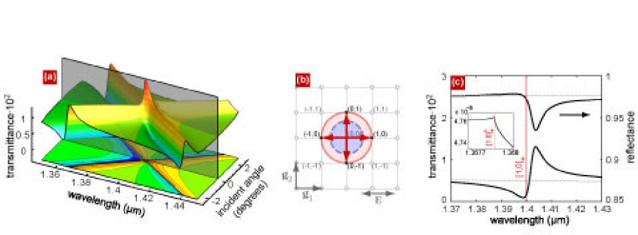
In Fig. 7 (a, c) the enlarged fragments of Figs. 5 and 6 (a) are shown in the vicinity of resonance for the incident plane orientated parallel to and the polarization of the incident wave such that . Note that the resonance features are heavily dependent upon the polarization of the incident wave and the orientation of the incident plane, cf. transmittance dependencies shown in Fig. 6 (a), (b), (c) and (e). For instance, for polarization, when belongs to the incident plane parallel to (), in the vicinity of normal incidence, only the pair of the resonance waves are excited, see Subsection II.3. These waves correspond to diffraction orders (TCs are equal to zero). In Fig. 6 (a) and in Fig. 7 (a) one can observe the intersection of the two resonance features, relevant to the intersection of two resonance curves: and , Fig. 6 (d). In deflecting from the normal incidence, the projection of onto becomes nonzero, and it appears as an feature in Fig. 6 (a) close to the coinciding resonance curves in Fig. 6 (d). When is perpendicular to the incident plane parallel to (), [-polarization, see Fig. 6 (b)], the only excited pair of resonance waves comply with the diffraction orders (resonance coefficients ). If the incident plane is oriented at , then two pairs of resonance waves are excited both for - and -polarizations of the incident wave in the vicinity of normal incidence [in Fig. 6 (c,e) -polarization case is shown]. The resonance waves correspond to diffraction orders and . In Fig. 6 (f) this appears as the intersection of four resonance curves: and , coinciding for .
The wavelength dependence of the zeroth-order wave has the typical Fano-type profile which consists of the neighbouring minima and maxima, see Fig. 7 (c). This is due to the interference (see Subsection II.2) between nonresonance and resonance transmittance mechanisms. The maxima of the Fano profile is red-shifted as compared with the wavelength of the SPP existing at the nonmodulated metal-quartz interface. This shift is mainly due to the scattering by modulation through the diffracted inhomogeneous waves, and partially due to the finite film thickness.
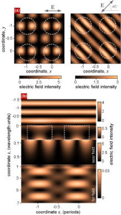
The amplitude of the excited resonance waves is proportional to Fourier harmonic amplitude, while the zeroth-order transmittance and reflectance are proportional to its squared value, as it follows from Eqs. (24)-(II.2) (see also Appendix B). Therefore, this harmonic plays the most important role in the excitation of the SPP eigenmode for resonance. Actually, the structure of the eigenmodes in the modulated film (dressed SPPs) define the distribution of the near-field completely. As indicated in Subsection II.3, the only excited eigenmodes are high-frequency ones. For instance, when is oriented along , the distribution of the squared field on the quartz side take the form , similary to the spatial field distribution for the twofold coupling given by Eq. (34). Indeed, this is in compliance with the left-hand part of Fig. 8 (a). In the general case, when is oriented relative to at an arbitrary angle , the near-field structure is formed by the interference of the eigenmodes. One of them corresponds to and the other is for . As a result the field on the interface has the form , where the “weight” coefficients () are proportional to () respectively. This interference is clearly seen in the right-hand part of Fig. 8 (a). Thus the near-field structure is in excellent agreement with the experiment, cf. Ref. shadows_APL_02, .
Consider the field distribution along axis, see Fig. 8 (b).
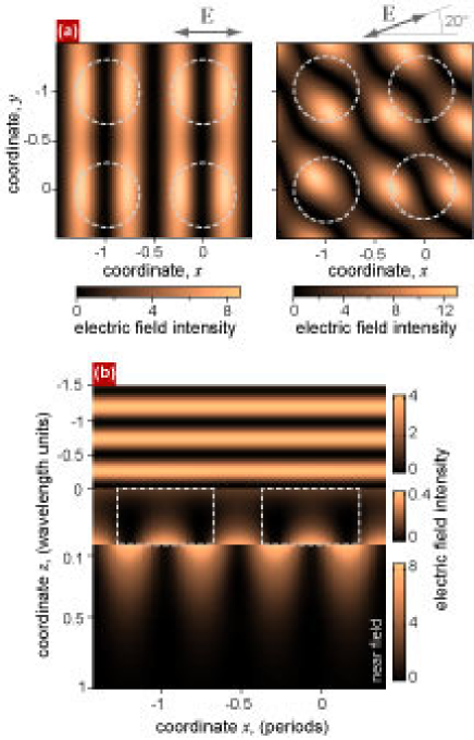
Since the far-side SB SPP resonances provide small reflectance dips [the lowest reflectance is of order of 93%, see Fig. 7 (c)], we notice a clear interference pattern along axis in the air half-space. The field penetrating into the film decays exponentially, and excites a SB SPP at the quartz-metal interface. The SPP field has a well-pronounced “torch” structure. It decays exponentially into the film at a distance of order of skin-depth, , where and decays into the dielectric medium (quartz) at a distance of , where . Note that the field pattern along axis in the film is shifted to a half-period with respect to the pattern in the quartz. This is because the SPP electric field in the metal has predominantly tangential-to-interface component as compared with a dielectric where the electric field has predominantly normal to the interface component. The intensity of the far field in the quartz half-space is constant, since there exists only one propagating wave (at zeroth diffraction order).
III.2 Polarization properties of resonance: dependence upon the inclusion shape
In this subsection we give a theoretical interpretation of the recent experimentshole_shape_PRL04 ; shape_localized_PRB05 concerning the influence of the hole shape on ELT through periodic hole arrays within the framework of our theory. Moreover, we describe the transmittance behavior while changing the polarization of the incident light.
Consider a silver film sandwiched between an air superstrate and quartz substrate with modulation symmetry caused by the inclusions of rectangular cross-section. This symmetry reduces to symmetry for a circle cross-section of inclusions. Now let us give a close consideration to the SB fourfold SPP resonance at strictly normal incidence. As was discussed above, for symmetry structures the polarization of the transmitted radiation depends upon the polarization of the incident wave. Suppose that the direction of is parallel to the small side of the rectangular, . If the incident-wave electric field is oriented along [], the incident wave magnetic field is then matched with that of [] SPP pairs having wavevectors [] for normal incidence, see Fig. 7 (b). According to our approach, the transmittance coefficient, , is proportional to () with a of polarization along (). This leads to for round cross-section and [] for rectangular cross-section with orientation along () [see Eqs. (II.4), (41)]. We take the same geometrical parameters for periodic arrays as in Ref. hole_shape_PRL04, , i.e. ; for small rectangles and for large ones; and for the circle diameter which corresponds to the resonance position at . Taking the film thickness to be equal to 3 skin depths, , and the inclusion impedance to be , where is taken for the silver, we obtain the transmittance of order , which is nearly 7 times higher than the transmittance through the unmodulated film.
When is directed along , the zeroth-order transmittance amplitude is proportional to a squared harmonic amplitude. This amplitude increase for large rectangles as compared with the circles and this results in redshift and in a rise of the transmittance maximum, see Fig. 9 (a).
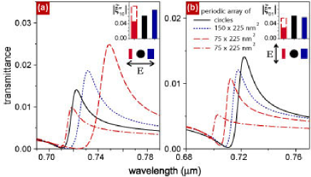
This tendency is in accordance with the experiment. But for the small rectangles the resonance harmonic amplitude is the smallest one and this leads to blueshift and a decrease in the transmittance maxima as compared with the circles and large rectangles. This is not what was observed experimentally. We may eliminate this discrepancy only by adjusting the impedance of the inclusion. We use this adjustment because, in our approximation, we do not allow for the influence of the modulation upon the volume of the film, but the modulation appears in the boundary conditions only. In other words, the fields decay into the film with the same decrement at any cross-section by a plane parallel to axis . On the other hand, it is evident that under a strong modulation, with the impedances of inclusions and the film differing greatly, the fields in the inclusion and in the volume of the film decay in a different way. For instance, inside the holes the field show a weaker decay than in the metal regions. Thus, adjusting the impedance, we have found that for the transmittance maximum corresponding to the small rectangles is redshifted and increased as compared with the large rectangulars and circles as it was in the experiment. If we rotate the polarization plane by so that is directed along , see Fig. 7 (b), the transmittance will depend upon the inclusion shape differently. In Fig. 9 (b) the transmittance is shown for different inclusion shapes both with equal for all shapes and when the modulation amplitude is taken from the previous case for the small rectangles.
On the one hand, supposing the inclusion impedance, , to be constant, but at the same time changing the inclusion shape, we can predict the true transmittance through arrays of nanoparticles immersed into the film (each nanoparticle corresponds to an inclusion). On the other hand, by adjusting the inclusion impedance for different shapes, we may provide the qualitative coincidence with experimental measurements of ELT through hole arrays.
Consider the experiment of Ref. shape_localized_PRB05, , where the effect of aspect ratio of rectangular holes on the transmittance of periodic arrays of subwavelength holes in optically thick metal films was measured. It was found that as the electric field, , of the incident light is directed along the short axes of the holes, , the zeroth-order transmittance peak (corresponding to SPP resonance) increases and suffers a redshift when the aspect ratio of the holes, , is enlarged. Conversely, it was discovered that as is directed along the long axes of the holes, , transmittance peak decreases and undergoes a blueshift when the aspect ratio of the holes is enlarged. The experimental measurements was also confirmed by strict numeric calculations. The authors attribute the discovered polarization dependence of the transmittance upon the the ratio of the rectangular holes to a result from interaction between SPP resonances at the surface of the metal and shape resonances inside the holes.
We hold to a different, simpler point of view. It is obvious that the localized eigenmodes are not supported by the structures under examination. But the calculations we do not present here within the framework of our simple model exhibit the same behavior of the transmittance, as in Ref. shape_localized_PRB05, . We have taken the geometrical parameters of the inclusions the same as in Ref. shape_localized_PRB05, . When is parallel to , the amplitude of the excited SPP is proportional to , which increases as the aspect ratio increases. Therefore this leads to the transmittance peak growth and redshift. On the contrary, when is parallel to , the amplitude of the excited SPP is proportional to , which decreases with an aspect ratio increase. This brings about the transmittance peak decrease and blueshift. Thus, the polarization behavior may be successfully described under the assumption of the excitation of purely interface SPPs.
III.3 resonance
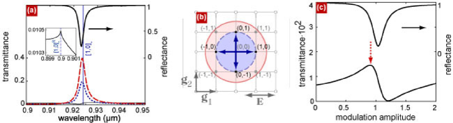
Now examine the resonance near () in the vicinity of close-to-normal incidence, see Figs. 5, 6. This fourfold resonance is consistent with excitation of a SB SPP at the metal-quartz interface, see Fig. 10 (b). dependence is shown in Fig. 6 (square regions) for different polarizations and orientations of the incident plane. Fig. 10 (a) and (c) are the enlarged fragments of Fig. 6 (a) and Fig. 5.
Now we explain the dependence of the transmittance upon and in the vicinity of resonance, see the second (from above) solid square regions in Fig. 6. For polarization, when belongs to the incident plane parallel to (), both the pairs of the resonance waves corresponding to and diffraction orders are excited in the close-to-normal incidence region. Accordingly, in Fig. 6 (a) and in Fig. 10 (a) one can see the intersection of the two features that are relevant to two pairs of coinciding resonance curves, and , in Fig. 6 (d). Evidently, the similar dependencies take place if is perpendicular to the incident plane parallel to () [-polarization, see Fig. 6 (b)]. If the incident plane is oriented at , then for -polarization of the incident wave [see Fig. 6 (c)] the magnetic field is parallel to . And the only excited pair of resonance waves in the vicinity of normal incidence corresponds to the diffraction orders (resonance coefficients ). This pair provides an extremum of the transmittance close to the coinciding resonance curves in Fig. 6 (f). For the nondegenerated case, in the terms of classifying the resonance curves, Fig. 6 (e), there is the intersection of four features in the transmittance which conforms to four distinct resonance curves: .
The principal difference of resonance from the resonance considered above is that additional propagating waves exist in the quartz substrate. Namely, the waves having diffraction orders provide the nonzeroth-order ELTOurs_JETPHL_04 ; film_PhysRev due to the scattering of the resonance waves through amplitudes . This scattering contributes additionally to the resonance width. Black dots, placed within the solid circle in Fig. 10 (b) indicate the positions for tangential components of wavevectors of these waves. On the other hand, the resonance is less pronounced as compared with one not only because of additional radiation losses. As one can see from Fig. 4, the amplitude , which is responsible for resonance waves excitation within the limits of the main approximation, is smaller than the amplitude , and hence the SPP excitation is less effective. It should be noted that the SPP is excited not only owing to first-order scattering of the incident wave by resonance harmonics, but also due to the higher-order scattering processes. While the cubic processes (proportional to ) can be neglected, the second-order scattering may compete with the linear one in some regions of parameter , going beyond the approximation (19)-(22). Thus, for , the contribution to the amplitude of the resonance wave from the second order term, proportional to , is of the the same order as the contribution from the linear term proportional to .
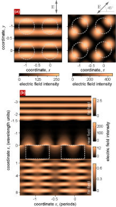
All the propagating field harmonics contribute to the transmitted energy flux in the substrate media. While the parts of the energy flux relating to the zeroth and nonzeroth diffraction orders are well separated at a grate distance from the film, they are overlapped in the region sufficiently close to the film. Therefore, when making the experimental measurements, the detector position is crucial: if it is far away from the film, it fixes either zeroth-order flux, [see Fig. 10 (c), solid curve], or nonzeroth one, [see Fig. 10 (c), dotted curve], depending upon detector orientation relative to the film. In case the detector is in the close-to-the-film vicinity, it fixes the total flux [see Fig. 10 (c), dashed curve]. The interference pattern resulting from the existence of several homogeneous waves is quite noticeable in the far-field region in Fig 11 (b). The near-field structure may be understood in the same way as in the case of resonance. For instance, when is oriented along , the intensity distribution on the quartz side for strictly normal incidence is proportional to , see the right-hand part of Fig. 11 (a). When is oriented with respect to at , the near-field structure is formed by the interference of the eigenmode for and the eigenmode for , so that the field at the interface takes the form . This is in accordance with the left-hand part of Fig. 11 (a). It is interesting to note that the field intensity is increased additionally in the regions where the inclusions are located.
III.4 resonance
It should be emphasized, that SB SPP resonances pertinent to the superstrate face provide strong nonzeroth-order ELT on condition that . It is clear from the geometrical reasons. Since the modulus of the wavevectors in the superstrate media are less than those of the substrate media, the metal-superstrate SPP wavevector () corresponds to the propagating wave in the substrate media. This enables SPP leakage without scattering via the modulation. Another feature of superstrate resonances is far deeper minima in the zeroth-order reflectance as compared to the resonance on the substrate face. This is because the zeroth-order reflectance is strongly dependent upon the efficiency of SPP excitation. The incident light excites SPP on the superstrate face directly via the modulation, while for excitation on the substrate face, amplitude of the light decreases prior to the excitation caused by the tunneling through the film (thereby making the excitation process less effective).
Let us discuss the SB metal-air SPP resonance that corresponds to the transmittance (reflectance) maximum (minimum) at in Fig. 5. The enlarged fragment of the wavelength-dependent zeroth- and nonzeroth-order transmittances are shown in Fig. 12 (a). While the zeroth-order transmittance profile is similar to that corresponding to the resonance [their maximal amplitudes are practically equal, being of order ], the reflectance has considerably deeper minima [cf. Fig. 12 (a) and Fig. 7 (c)], in accordance with the above-mentioned general property of superstrate resonances. The amplitudes of nonzeroth-order outgoing transmitted waves exceed significantly the zeroth order amplitude [compare the solid curve for and the dotted curve for in Fig. 12 (a)] since their amplitudes are of order . It follows from the Eq. (B). This estimation is quite universal and coincide with that made using the expression Eq. (24) for the simplest resonance. The enhanced nonzeroth-order transmission may be used for developing the light-splitters, since the waves propagate at an angle relative to axis. The unique feature of such a splitter is that all the four nonzeroth-order waves are linear polarized. Their polarization coincides with that of SPPs excited.KNN_PhysRev
Note that not only diffraction orders are responsible for the nonzeroth-order ELT. As seen from Fig. 12 (b), the diffraction orders correspond to the propagating waves in the quartz substrate as well. The resonance scattering contributes to these amplitudes amplitudes so that they are proportional to . Their intensities have been taken into account when calculating the total transmitted energy flux shown by the dashed line in Fig. 12 (a).
It has to be pointed out that the transmittance behavior with respect to the polarization of the incident wave change, in the vicinity of resonance, is similar to that in the vicinity of resonance. This is described in Subsection III.1. (cf. the dashed square regions of and the upper solid square regions in Fig. 6.) The near-field distribution in plane is likewise equivalent to that corresponding to resonance, but now the field is localized at the air-metal interface. This is clearly seen in Fig. 13 (b). Note that the far-field structure has the form of the interference pattern both in the air and in the quartz half-spaces. The pattern in the air superstrate is due to the interference between incident and reflected zeroth-order waves: we see from Fig. 12 (a) that the reflectance is of order of 20% in the resonance. The pattern in the quartz substrate is caused by the interference between the transmitted zeroth-order and nonzeroth-order waves.
Let us illustrate the dependence of the zeroth and non-zeroth order transmittance upon the modulation amplitude. The transmittance (reflectance) has the well-defined maximum at , which corresponds to , see Fig. 12 (c). So, as expected, this value of the modulation amplitude guarantee exactly the resonance harmonic optimal value, see discussion below Eq. (II.2), and, therefore, leads to the optimal transmittance value.
III.5 Double bounday SPP
DB SPPs for nonsymmetrically-surrounded film exist under a specific relation between angle of incidence, wavelength, structure spacing, and dielectric permittivities of the surrounding mediafilm_PhysRev . For instance, in the case of strictly normal incidence the excitation of four resonance waves in the superstrate () having multiindexes , and four resonance waves in the substrate () having multiindexes may take place if . We do not consider this specific set of parameters in the present paper, but study DB SPPs in a symmetrically-surrounded film below.
IV DB SPP resonances in the symmetrically-surrounded film
To the best of our knowledge, the earliest observations of the ELT through hole arrays due to the DB SPP excitation were performed in Refs. Ebbesen2001_Opt, ; Ebbesen_theory_PRL01, . Moreover, in Ref. Ebbesen2001_Opt, the array was formed in the metal film surrounded by quartz from one face and by a liquid with a close-to-quartz dielectric constant from the other face, while Ref. Ebbesen_theory_PRL01, deals with a free-standing film. In the above experiments the matching of wavevectors at the opposite interfaces was made to excite a DB SPP. This considerably increased the ELT efficiency in zeroth diffraction order as compared to the SB SPP excitation for a nonsymmetrically surrounded film.
As known, there exist two SPP modes in the nonmodulated symmetrically-surrounded metal film, see Sec. II. One of them, a LR mode, corresponds to the nonsymmetric surface charge distribution, and higher frequency and Q-factor as compared to the other, SR mode. A remarkable feature is that the similar situation is inherent to the mechanical system of two coupled damping oscillators which is nothing else but a classical analog of coupled SPPs in the film, see Appendix A. If the modulation is not too high, LR and SR modes undergo shift and widening, but remain well-separated from one another. This is not exactly what is observed in the experiments using subwavelength hole arrays. The modulation amplitude of the arrays is too high to distinguish well the difference between LR and SR modes.
The transmittance spectra of a symmetrically-surrounded film is shown in Fig. 14. One can see the four peaks: the first pair is , in the vicinity of DB SPP resonance, and the second pair is , in the vicinity of DB SPP resonance. Indexes , comply with LR and SR modes. In Figs. 15 (a-c) and (e) the transmittance spectra are presented as functions of the wavelength and/or energy and the incident angle for different polarizations of the incident wave. In Figs. 15 (d,f) the resonance curves are shown by solid lines.
Consider the deviations from the normal incidence. In Figs. 15 (a-c) the special symmetry is shown, that is, the incident plane is oriented relative to at and . This complies with coincidence of the resonance curves, see discussion below formula (18). It is seen in the vicinity of resonance shown by square regions in Fig. 15. In Figs. 15 (a-c) from six to two resonance features belong to these regions. These features correspond from six to two resonance curves in Figs. 15 (d,f). Oppositely, in Fig. 15 (e) the transmittance contour plot is shown for non-specific geometry, and therefore, eight features (or, eight curves) belong to each vicinity according to fourfold DB SPP.
Note the two features in Fig. 14. First, the widths of resonance peaks (dips) are less for LR modes than for SR modes. This is due to the higher Q-factor of LR mode as compared with SR mode, that can be easily explained in terms of field structure of SPP modes in the metal. -dependence of the electric field tangential component for LR and SR eigenmodes is defined by Eq. (35). Since the amplitude of the tangential component of the electric field is higher than the -component within the film, vector makes the main contribution to the loss power, , so that
| (42) |
In view of Eq. (35), one can see that the Ohmic losses of SR mode is higher than that of LR mode, , which leads to the higher Q-factor of LR mode as compared with SR mode.
Second, the resonance peaks for LR and SR modes is strongly dependent upon the exponential index appearing in the field approximation inside the film. In other words, assuming that in Eq. (II.1) is complex and taking into account both real and imaginary parts of the impedance of the conductor in Eq. (II.1) the transmittance maxima (reflectance minima) for LR mode are higher (deeper) than those for SR mode. And vice versa if dissipation losses are neglected. As was indicated in the experimental paperener.transfer_science04 , where plasmons were studied in the symmetrically surrounded corrugated silver film, “this process has a complex distance (film thickness) dependence”, that is “for thin silver films ( ), the symmetric coupled SPP is strong but extremely sharp, whereas the antisymmetric SPP is broad but weak. As the silver thickness increases, the symmetric mode weakens and broadens, whereas the antisymmetric mode sharpens and intensifies”. Thus, to our opinion, the discussed question of the resonance peaks for LR and SR modes needs further careful studying.
IV.1 resonance
Now consider the DB fourfold SPP resonance for strictly normal incidence. The enlarged fragment of Fig. 14 in the vicinity of the peaks is shown in Fig. 16 (a). The LR and SR resonances are blueshifted as compared with the wavelengths for nonmodulated film SPPs marked by the vertical lines. Analogously to the SB SPP resonance, the amplitudes of the resonance waves are proportional to , and the resonance contribution to the amplitude of the only propagating zeroth-order wave is proportional to .
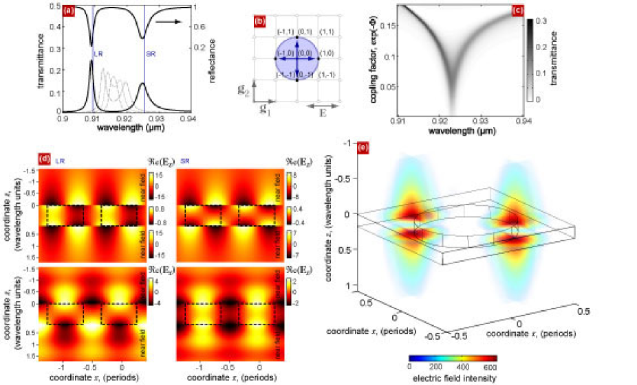
For a SDB resonance, the transmittance and reflectance have two extremums. This results from the excitation of LR and SR SPPs, corresponding to the zeros of the denominators in Eqs. (II.2), (II.2) (and Appendix B). The peak value of the transmittance for optimal modulation amplitude may be estimated as , which exceeds the transmittance through the unmodulated film by a factor of .
The distance between the two extremums of the transmittance (reflectance) may be estimated by extracting the difference between the wavelengths corresponding to SR (LR) SPPs from the dispersion relations Eq. (17). Using , (where we have replased by the SPP wavevector, ), we find for the frequencies , where for the LR mode and for the SR mode . In terms of wavelength we have for the relative difference between the wavelengths , where is of order of , . The modulation contributes additionally to this difference, and this contribution may be found from the dispersion relation , Eq.(27), see Ref film_PhysRev, . As the film thickness increases, the distance between and decreases, see Figs. 16 (a), (c). When the resonance width, , takes the value of order of the splitting between the LR and SR modes, [which occurs for film thickness ], the two maxima of the two-humped resonance curve become indistinguishable.
The near-field distribution for LR and SR SPPs is shown in Fig. 16 (d), (e). One can see that LR (SR) mode is antisymmetric (symmetric) with respect to the tangential component of the electric field and the surface charge distribution (the surface charge sign coincides with the sign of the production , where is -component of the surface normal vector pointing out of the metal).
V Conclusions
We have treated analytically the resonance optical properties of periodically-modulated optically-thick metal films. Explicit analytical expressions for transformation coefficients related to any diffraction order have been obtained. In studying the complicated multiple resonances, we have ascertained that the most of the physical properties of ELT may be well understood in terms of the simplest example of a solitary resonance (when SPP is excited in a single diffraction order). We have examined and explained not only the amplitude and polarization dependencies of the transmittance and reflectance upon the parameters (angle of incidence, wavelength, tilting angle, film thickness, etc.), but also the field structure of the diffracted light. We have shown that according to the conception of interface SPPs excitation, the polarization dependencies of the light diffracted by the periodical array may be adequately described. We have compared our theoretical calculations with recent experiments and found an excellent coincidence. We have shown that for hole arrays (which are in most cases used for the experimental study of ELT) it is difficult to make a distinction between the long-range and short-rang SPP modes excitation caused resonance features since the radiative broadening exceeds the splitting between them for rather thick films. In this sense structures with weak modulation (say, the periodical arrays of metal nanoparticles immersed into a metal film, corrugated shallow diffraction gratings) are more preferable. Moreover, the efficiency of SPP excitation may be much higher for the structures with weak modulation as compared to the structures with holes being included. This is due to the existence of the optimal modulation amplitude. It was demonstrated that in some cases the energy flux corresponding to nonzeroth diffraction orders, exceeds that for zeroth-order. This can have a strong influence upon the results of experimental measurements.
A highly instructive analogy was drawn between motion of the monochromatic force driven system of two weakly coupled classical oscillators and ELT effect.
VI Acknowledgements
The authors acknowledge financial support from the INTAS YS grants Nr 05-109-5206 and Nr 05-109-5182.
Appendix A Two coupled damping oscillators
The enhanced transparency and other resonant properties of the periodically modulated metal film can be described by analogy with a simple mechanical system consisting of two weakly coupled harmonic oscillators under the action of the harmonic force applied to one of them see Fig. 17 (a).
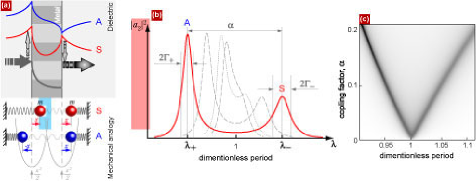
An oscillation amplitude of the second oscillator is strongly dependent on the frequency of the force applied to the first oscillator and can reach amplitudes of order of the amplitude of the first uncoupled oscillator. We will concentrate on the system of two identical oscillators which has the analogy with the ELT through symmetrically-surrounded film. Lagrangian of this system is
| (43) |
where dots denote time derivatives, the term is responsible for weak coupling, , and the two last terms are for the forces acting on the oscillators. Adding to the Lagrangian we arrive at the two masses linked by a string with elasticity coefficient . Units are such that the unperturbed frequency equals unity. The losses are taken into account by the dissipative functionLandau ,
| (44) |
where (non-negativeness of ). Below the dissipation is supposed to be small, . Then equations of motion are
| (45) |
In normal coordinates, , which correspond to the inphase () and antiphase () oscillations (symmetric and antisymmetric with respect to transposition modes), we split the system (45),
| (46) |
where .
Solution of the corresponding homogeneous system is
| (47) |
where the complex eigenfrequencies are and (, ),
| (48) |
Eigenfrequency of the inphase (symmetric) mode is lower than that for antiphase (antisymmetric) one, if the damping is small, . This is in compliance with the modes of the symmetrically-sandwiched film. Namely, eigenfrequency of the LR (antisymmetric) SPP is lower than that for SR (symmetric) one, see discussions in the Subsection IV.1. In turn, the corresponding decrement, , is higher (lower) for (). Note that the case with holds for different active losses for symmetric and antisymmetric polariton modes. This difference is due to the fact that the high-frequency mode has a lower mean value of the electric field in the film, and, hence, lower losses and a higher -factor.
The specific solution of the dynamic equations (46) for harmonic driving forces being applied, , is
| (49) |
where ,
| (50) |
Thus, displacements of the forced oscillations are , ,
| (51) |
Let excitation of the system be caused by a driving force applied to the first oscillator, , . This is analogous to the diffraction problem, where only one wave is incident onto a face of the metallic film. If the dissipation is small, , then there exist two pronounced maximal magnitudes of in the vicinity of the frequencies , where , . The splitting of the resonance maxima is approximately , and the up- (low-) frequency resonance widths are . As decreases, the distance between resonance peaks diminishes, and for they overlap, see Fig. 17 (b), (c). The mechanical coupling factor is analogous to that arising in the EM problems: for the splitting of the SPP modes in the film this factor is , compare Fig. 17 (c) and Fig. 16 (c).
For the amplitude of the enforced oscillator vanishes at the unperturbed eigenfrequency, . This well-known effect of the resonance damping (which is extensively used in shipbuilding) also shows an analogy with the ELT problem, where Fano minima arise in the amplitudes of the fields.
In a similar way one can draw an analogy for the nonsymmetrically-sandwiched film. In that case the mechanical system consist of two oscillators of different masses.
Thus, some physical properties of the ELT phenomena are quite general. At least, the similarities with the simplest classical mechanical systems may be established.
Appendix B Transformation coefficients for fourfold resonance in cases of and symmetries
In the case of symmetry which implies the following properties of modulation impedance:
the resonance matrix possesses the symmetry properties. The resonance TCs in the vicinity of normal incidence for , or resonance are related as , . This leads to the essential simplification of Eqs. (19), (22): the resonance matrix can be reduced to a matrix . Thus, the TCs are written as
| (52) |
where , or ,
| (53) |
| (54) |
where . If the modulation has symmetry, the zeroth-order TCs allow additional simplifications
| (55) | |||||
Notice that the zeroth-order TCs are diagonal in polarization, i.e. the polarization of zeroth-order reflected/transmitted wave is the same as that of the incident wave.
References
- (1) H. Raether, Surface plasmons, (Springer-Verlag, New York, 1988).
- (2) V. M. Agranovich and D. L. Mills, Surface Polaritons, (Nauka, Moscow, 1985).
- (3) A. V. Zayats, I. I. Smolyaninov, A. A. Maradudin, Phys. Rep. 408, 131 (2005)
- (4) W. L. Barnes, A. Dereux, and T. W. Ebbesen, Nature 424, 824 (2003).
- (5) T. W. Ebbesen, H. J. Lezec, H. F. Ghaemi, T. Tio, and P. A. Wolff, Nature 391, 667 (1998).
- (6) H. F. Ghaemi, T. Thio, D. E. Grupp, T. W. Ebbesen, and H. J. Lezec, Phys. Rev. B. 58, 6779 (1998).
- (7) H. A. Bethe, Phys. Rev. 66, 163 (1944).
- (8) A. Krishnan, T. Thio, T. J. Kim, H. J. Lezec, T. W. Ebbesen, P. A. Wolf, J. Pendry, L. Martin-Moreno and F. J. García-Vidal, Opt. Com. 200, 1 (2001).
- (9) L. Martín-Moreno, F. J. Garsía-Vidal, H. J. Lezec, K. M. Pellerin, T. Thio, J. B. Pendry, and T. W. Ebbesen, Phys. Rev. Lett. 86, 1114 (2001).
- (10) J. Dintinger, S. Klein, F. Bustos, W. L. Barnes, and T. W. Ebbesen, Phys. Rev. B. 71, 035424 (2005).
- (11) Y. Liu, and S. Blair, Opt. Lett. 28, 507 (2003).
- (12) W. A. Murray, S. Astilean, and W. L. Barnes, Phys. Rev. B 69, 165407 (2004).
- (13) A. Degiron, H. J. Lezec, W. L. Barnes, and T. W. Ebbesen, Appl. Phys. Lett. 81, 4327 (2002).
- (14) S. C. Hohng, Y. C. Yoon, D. S. Kim, V. Malyarchuk, R. Müller, Ch. Lienau, J. W. Park, K. H. Yoo, J. Kim, H. Y. Ryu, and Q. H. Park, Appl. Phys. Lett. 81, 3239 (2002).
- (15) F. J. Garcia-Vidal, L. Martín-Moreno, and J. B. Pendry, J. Opt. A: Pure Appl. Opt. 7, S97 (2005).
- (16) M. Sarrazin, J.-P. Vigneron, and J.-M. Vigoureux, Phys. Rev. B 67, 085415 (2003).
- (17) E. Popov, N. Nevière, S. Enoch, and R. Reinisch, Phys. Rev. B 62, 16100 (2000).
- (18) R. Petit, M. Neviere Light propagation in periodic media. Differential Theory and Design, (Marcel Dekker, New York, 2003).
- (19) L. Salomon, F. Grillot, A. V. Zayats, and F. de Fornel, Phys. Rev. Lett. 86, 1110 (2001).
- (20) D. Gérard, L. Salomon, F. de Fornel, A. V. Zayats, Optics Express 12, 3652 (2004).
- (21) U. Schröter and D. Heitman, Phys. Rev. B 60, 4992 (1999).
- (22) P. T. Worthing and W. L. Barnes, Appl. Phys. Lett. 79, 3035 (2001).
- (23) I. Arutsky, Y. Zao, and V. Kochergin, Opt. Lett. 25, 595 (2000).
- (24) N. Bonod, S. Enoch, L. Li, E. Popov, and M. Nevière Opt. Expr. 11, 428 (2003).
- (25) S. A. Darmanyan and A. V. Zayats, Phys. Rev. B 67, 035424 (2003).
- (26) A. M. Dykhne, M. K. Sarychev, and V. M. Shalaev, Phys. Rev. B 67, 195402 (2003).
- (27) S. A. Darmanyan, M. Nevière, and A. V. Zayats, Phys. Rev. B 70, 075103 (2004).
- (28) Z. D. Genchev and D. G. Dosev, J. Exp. Theor. Phys. 99, 1129 (2004).
- (29) Yu. P. Bliokh, Phys. Rev. Lett. 95 , 165003 (2005).
- (30) A. Benabbas, V. Halté, J.-Y. Bigot, Opt. Expr. 13, 8730 (2005).
- (31) A. V. Kats and A. Yu. Nikitin, JETP Lett. 79, 625 (2004).
- (32) A. V. Kats and A. Yu. Nikitin, Phys. Rev. B. 70, 235412 (2004).
- (33) A. V. Kats, M. L. Nesterov, and A. Yu. Nikitin, Phys. Rev. B. 72, 193405 (2005).
- (34) S. Park, G. Lee, S. H. Song, C. H. Oh, and P. S. Kim, Opt. Lett. 28, 1870 (2003).
- (35) K. G. Lee, and Q.-H. Park, Phys. Lett. 95, 103902 (2005).
- (36) G. Laurent, N. Félidj, S. Lau Truong, J. Aubard, G. Lévi, J. R. Krenn, A. Hohenau, A. Leitner, and F. R. Aussenegg, Nano Lett. 5, 253 (2005).
- (37) M. D. Malinsky, K. L. Kelly, G. C. Schatz, and R. P. V. Duyne, J. Am. Chem. Soc., 123, 1471 (2001).
- (38) Y. Xia and N. J. Halas, MRS Bulletin 30, 338 (2005).
- (39) K. J. K. Koerkamp, S. Enoch, F. B. Segerink, N. F. Hulst, and L. Kuipers, Phys. Rev. Lett. 92, 183901 (2004).
- (40) A. Degiron and T. Ebbesen, J. Opt. A: Pure Appl. Opt. 7, S90 (2005).
- (41) K. L. van der Molen, K. J. Klein Koerkamp, S. Enoch, F. B. Segerink, N. F. van Hulst, and L. Kuipers, Phys. Rev. B 72, 045421 (2005).
- (42) Gang Sun and C. T. Chan, Phys. Rev. E 73, 036613 (2006).
- (43) T. A. Kelf, Y. Sugawara, R. M. Cole, and J. J. Baumberg, Phys. Rev. B 74, 245415 (2006).
- (44) T. V. Teperik, V. V. Popov, F. Javier García de Abajo, M. Abdelsalam, P. N. Bartlett, T. A. Kelf, Y. Sugawara, J. J. Baumberg, Opt. Expr. 14, 1965 (2006).
- (45) R. Gordon, A. G. Brolo, A. McKinnon, A. Rajora, B. Leathem, and K. L. Kavanagh, Phys. Rev. Lett. 70, 037401 (2004).
- (46) J. Elliott, I. I. Smolyaninov, N. I. Zheludev and A. V. Zayats, Opt. Lett. 29, 1414 (2004).
- (47) E. Altewischer, C. Genet, M. P. van Exter, J. P. Woerdman, P. F. A. Alkemade, A. van Zuuk and E. W. J. M. van der Drift, Opt. Lett. 30, 90 (2005).
- (48) C. Genet, E. Altewischer, M. P. van Exter, and J. P. Woerdman, Phys. Rev. B 71, 033409 (2005).
- (49) F. Miyamaru, and M. Hangyo, Appl. Opt. 43, 1412 (2004).
- (50) S. A. Maier, Current Nanoscience, 1, 17 (2005).
- (51) J. Homola, S. S. Yee, Gunter Gauglitz, Sensors and Actuators B 54, 3 (1999).
- (52) J. Homola, Anal. Bioanal. Chem. 377, 528 (2003).
- (53) P. V. Lambeck, Meas. Sci. Technol. 17, R93 (2006).
- (54) A. G. Schuchinsky, D. E. Zelenchuk, and A. M. Lerer, J. Opt. A: Pure Appl. Opt., 7, S102 (2005).
- (55) J. Saxler, Surface Plasmon Polaritons at Terahertz Frequencies on Metal and Semiuctor Surfaces (Diploma Thesis, Aachen University, Aachen 2003).
- (56) F. Yang, J. R. Sambles and G. W. Bradberry, Phys. Rev. B 44, 5855 (1991).
- (57) J. J. Burke, G. I. Stegeman and T. Tamir, Phys. Rev. B 33, 5186 (1986).
- (58) A. V. Kats and A. Y. Nikitin, Proc. SPIE 5221, 218 (2003); 5477, 381 (2004).
- (59) M. Kretschmann, A. A. Maradudin, Phys. Rev. B 66, 245408 (2002).
- (60) P. Andrew and W. L. Barnes, Science 306, 1002 (2004).
- (61) N. Fang, H. Lee, C. Sun, and X. Zhang, Science 308, 534 (2005).
- (62) V. M. Zolotarev, V. N. Morozov, and E. V. Smirnova Optical constants of natural media, (Chemistry, Leningrad, 1984).
- (63) L. D. Landau and E. M. Lifshits, Classical Mechanics (Pergamon, Oxford, 1977).