Hysteresis in a system driven by either generalized force or displacement variables
Abstract
We report on experiments aimed at comparing the hysteretic response of a Cu-Zn-Al single crystal undergoing a martensitic transition under strain-driven and stress-driven conditions. Strain-driven experiments were performed using a conventional tensile machine while a special device was designed to perform stress-driven experiments. Significant differences in the hysteresis loops were found. The strain-driven curves show re-entrant behaviour (yield point) which is not observed in the stress-driven case. The dissipated energy in the stress-driven curves is larger than in the strain-driven ones. Results from recently proposed models qualitatively agree with experiments.
pacs:
81.30.Kf,75.60.EjI Introduction
Hysteresis is ubiquitous in many areas of physics. It is a signature of non-equilibrium effects and has attracted the attention of researchers for a long time and is still one of the most challenging subjects of research Bertotti06 . Typically, the phenomenon of hysteresis results in closed loops when plotting the external driving force (or field) vs. the generalized displacement (or vice versa). These two variables (external force and generalized displacement) are conjugate variables in the first principle of thermodynamics and depending upon the specific system, they can have different tensorial character. Nevertheless, in all cases their product renders the work performed on the studied system and the area enclosed within a closed loop gives the energy loss.
Among hysteretic systems, particular attention has been devoted to athermal cases Sethna2005 . In these cases, hysteresis is not due to competition between the fast driving rate and slow thermal relaxation, but rather it originates from the existence of very high energy barriers that can only be overcome when the system reaches local marginal stability limits Cao1990 ; Perez2001 . The continuous change in the driving force results in discontinuous changes in the conjugate displacement, giving rise to avalanche dynamics. Such dynamics has been observed in a wide variety of materials such as ferromagnetic Puppin2000 , ferroelectric Colla02 and martensitic Vives1994 materials; field-driven vortex motion in type-II superconductors Altshuler2004 , and pressure-driven condensation of 4He on mesophorous solids Lilly1993 , among others. Since most of these systems show common hysteretic behaviour they are catalogued under the name of ferroic materials Wadhawan2000 . They display first order phase transitions with an order parameter (exhibiting discontinuous behaviour), which corresponds to the generalized displacement. A common feature in these systems is the existence of long range effects arising from compatibility conditions.
From an experimental point of view, it is usually easier to control the force while the conjugate displacement is measured. For instance, in magnetic systems, the magnetic field is readily controlled and magnetic flux is measured. Although more difficult, it has also been possible to control the magnetic flux Grosse1977 - which is suitable for studying materials displaying a rapid increase of magnetization. Moreover, the control of the amount of gas (generalized displacement) instead of the chemical potential has been shown to be the most convenient procedure in a number of gas adsorption experiments Wong1990 .
For a macroscopic system in equilibrium, thermodynamic trajectories do not depend on which is the control variable (generalized force or displacement) because the two cases are related by a Legendre transformation Huang1987 . However, there is no reason to expect that out of equilibrium hysteresis loops obtained when controlling the force will be similar to those obtained when the control parameter is the generalized displacement. Such a situation has been very recently theoretically studied Illa2006a ; Illa2006b by making use of the Random Field Ising Model (RFIM) Sethna1993 , which is a prototype model for athermal hysteresis. Results predict significant differences in the hysteresis loops obtained in the force-driven case (external field ) to those obtained by driving the generalized displacement (magnetization ). It is the aim of the present paper to address this issue from an experimental point of view.
Martensitic transitions (MT) offer a unique scenario to undertake such a task. A MT is a displacive first-order transition which involves a change in symmetry Nishiyama1978 . In these ferroic systems, the transition can be induced by cooling but also by application of a mechanical stress. In this latter case, the driving force is the applied load, while the conjugate displacement is the elongation (or strain). Typical experiments are carried out using commercial tensile testing machines in which the control variable is the elongationfeedback . We have developed an experimental device which enables fine control of the applied force while the strain is monitored. In this paper we present experiments performed on the same specimen under both force and displacement control conditions. Results will enable a meaningful comparison of the hysteresis loops obtained in the two cases. In addition, comparison with the predictions of recent theoretical approaches Illa2006a ; Illa2006b will also be presented.
II Experimental
A Cu-Zn-Al single crystal was grown by the Bridgman technique. The nominal composition was chosen so that the (athermal) MT on cooling without stress takes place from a cubic (L21) to a monoclinic () structure slightly below room temperature (TM = 234K). The actual composition, obtained from electron dispersion analysis is Cu68.13Zn15.74Al16.13. A sample was mechanically machined from the ingot with cylindrical heads. The body of the sample has flat faces 35 mm long, 1.4 mm thick and 3.95 mm wide. The axis of the sample is close to the [001] crystallographic direction of the cubic phase. The sample was mechanically polished and then annealed for 20 min at 1073K, cooled in air down to room temperature and aged for 2 h in boiling water. This heat treatment ensures that the sample is in the ordered state, free from internal stresses and that the vacancy concentration is minimum at room temperature.
Special grips, which adapt to the heads of the specimen, can be used in both experimental devices. In the first device [Fig. 1(a)], a INSTRON 4302 tensile machine, (from now on strain-driven), the control parameter is the elongation while the load is continuously monitored. A second device (from now on stress-driven) was especially designed which enables control of the load applied to the sample while the elongation is continuously monitored [see Fig. 1(b)]. The device was adapted from that previously used by Carrillo et al. Carrillo97 . The upper grip is attached to a load cell hanging from the ceiling. Upper and lower ball-and-socket joints ensure good alignment. The lower grip holds a container that plays the role of a dead load. The load can be increased or decreased at a well-controlled rate by supplying or removing water by means of a pump. The strain is measured by a strain gauge attached to the sample. Since the stress needed to induce the MT is very sensitive to temperature, it is important to make sure that equivalent experiments are carried out at the same temperature. For this reason we use a cryofurnace (which enables temperature control to an accuracy of 0.1 K.) that can be adapted to both devices. In addition, in order to be able to compare the hysteresis loops obtained with the two devices, the same strain gauge was used in all experiments and the load cell for each set-up was calibrated using standard weights. For selected experiments at room temperature (without the cryofurnace), an optical microscope was incorporated into both devices, which enables in situ observations of microstructural changes.

III Results and Discussion
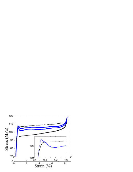
Fig. 2 shows typical results for the stress-strain curves obtained with the two devices. Upon increasing load, the parent cubic phase persists until it becomes unstable at a given value of the load, and the MT starts. Different hysteresis loops are observed in the two cases. Almost the entire strain-driven loop is enclosed within the stress-driven loop, which has a much larger area. In the stress-driven case, the stress slightly increases during the MT with an average slope that decreases as the driving rate is reduced. Extrapolation to zero rate still gives a finite (small) slope which can be caused by a weak concentration gradient along the axis of the sample. Different behaviour is observed in the strain-driven experiment. In this case, once the transition starts, the stress relaxes to a lower value (yield point effect) and then weakly oscillates around an almost constant value as the MT progresses. For both driving modes, when the transition ends, a new reversible elastic regime in the martensitic phase is reached. Upon unloading, the behaviour parallels that observed in the loading branch, but with hysteresis. In particular for the strain-driven experiment, before the end of the reverse transition, there is an increase in the stress which reproduces the yield stress effect.
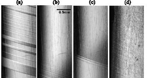
Optical observations have revealed significant differences in the early stages of the MT as shown in Fig. 3. The inset in Fig. 2 presents an enlarged view of the upper branch of the hysteresis loops on the low-strain region. The yield point in the strain-driven experiment is a consequence of re-entrant behaviour within the parent phase, associated with shrinkage and eventually the disappearance of previously formed martensitic plates. Such re-entrant behaviour is also observed on unloading, which causes the yield point of the lower branch of the hysteresis loop. The evolution of the microstructure associated with this re-entrant behaviour is illustrated by the micrographs in Fig. 3 (a),(b) and (c). The existence of a yield point in conventional strain-driven experiments has also been reported for other martensitic alloys Landa2004 ; Iadicola2004 . Moreover, computer simulations of the mechanical response of a strain-driven martensitic system also show a yield point Ahluwalia2006 .
For the stress-driven experiment there is a deviation of the pure elastic behaviour well below the yield stress. This effect is due to the nucleation of a set of very thin martensitic plates all over the sample, as illustrated by the micrograph in Fig. 3(d). Interestingly, this is the only region where the strain-driven loop is outside the stress-driven one. Actually, when driving the load, nucleation can occur at lower values since the system can more freely adapt to shape changes. For both driving mechanisms, steady state growth following the early stages is macroscopically similar, with parallel interfaces growing towards both ends of the specimen.
It is worth mentioning that the behaviour found in the present experiments for MT seems to be rather common in other systems. For instance, magnetization-driven magnetic hysteresis loops also show re-entrant behaviour Grosse1977 while no re-entrancy is present in magnetic field-driven loops. Furthermore, recent theoretical approaches and computer simulation studies for athermal plastic deformation Bouchbinder2006 provide curves with yield points when the control variable is the strain. Interestingly, wiggly trajectories and re-entrance have even been reported to occur in displacement driven nanoscale systems such as deformation of gold nanowires Rubio2001 and RNA unfolding Manosas2005 .
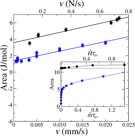
A relevant quantity in hysteretic systems is dissipated energy which is given by the area enclosed within the hysteresis loops. A noteworthy feature (see Fig. 2) is that the dissipated energy is much larger for the stress-driven case than for the strain-driven one. The dissipated energy is expected to depend on the driving rate of the control parameter. We have performed a series of experiments at different rates and the results of the area of the loops are plotted in Fig. 4 as a function of the rate. The dissipated energy increases with increasing rate in both cases. Extrapolation to zero rate with least-squares fits (lines) indicates non-vanishing hysteresis. Similar behaviour has also been reported for magnetic systems Nistor05 . It is also important to note that even in the zero-rate limit, the dissipated energy for the stress-driven experiment is always larger than for the strain-driven case.
We now discuss the experimental results presented here in relation to two recent approaches (in magnetic terminology) aimed at analysing -driven and -driven trajectories in the 3d-RFIM. Both models predict the existence of a yield point in the -driven loop in agreement with experiments. In the -driven case the force cannot relax and therefore the system can only reach the closer metastable states by a discontinuity in the generalitzed displacement. In contrast, for the -driven case the generalized displacement is constrained but the force is able to relax to lower values in such a way that the system is able to follow a trajectory that approaches equilibrium, thus resulting in a lower dissipation. The mechanism to relax the force is expected to depend on the details of the specific dynamic features of each system. The present experiments show that in MT the relaxation is achieved by retransformation. This is also the mechanism in the model in Ref. Illa2006b . The wiggly trajectories (see Fig. 2) can be interpreted within the framework of the models as being due to the specific distribution of disorder in the system. One of the models Illa2006a uses adiabatic (infinitely slow) dynamics for the -driven case which is the analogue of standard adiabatic dynamics introduced by Sethna et al. Sethna1993 in the -driven case. The definition of the measured (output) field assumes that the external force instantaneously equals the highest value of the internal forces. Consequently, the -driven loops have vanishing area. The strain-driven experiments presented here indicate that although the area is quite small compared with the force-driven situation, after extrapolation to zero driving rate, a certain amount of dissipated energy still remains.
We have extended the RFIM to incorporate the effect of a finite driving rate. For the -driven case such an extension was proposed PerezReche2004 by assuming an intrinsic average time for the avalanches to relax. In this case the finite-rate -driven loops can be constructed from the adiabatic -driven loops by considering the discontinuous step-like behaviour of the driving field with a certain in such a way that . This method allows the area of the loops as a function of the driving rate to be computed. Results obtained for a cubic system with size and standard deviation of the random-fields are shown in the inset of Fig. 4 (circles). Data correspond to averages over more than 1000 realizations of the random fields. We have considered a similar definition in the simulations of finite-rate -driven systems. It is assumed that the force is only able to relax at given values of the magnetization which are separated by so that . An example of the obtained results for the same system is also shown in the inset of Fig. 4 (squares). Results from numerical simulations satisfactorily reproduce the major features found experimentally, i.e. an increase in dissipation with increasing rate, and the fact that the dissipated energy is always larger for the force-driven cases. Only at low-rate limit do numerical data show the already mentioned tendency towards a vanishing area. Such a tendency is due to the assumption of the infinitely fast response of the system assumed in the models and therefore it is not corroborated by experimental data. The finite-rate models exactly predict that dissipation in the large-rate limit of the -driven dynamics reaches the zero-rate (adiabatic) limit of the -driven case (see inset of Fig. 4).
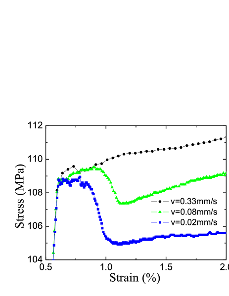
Experiments should provide a test of this prediction. As shown in Fig. 5, experimental data indicate a tendency to avoid re-entrance as rate is increased (the yield point is less and less pronounced) in such a way that the corresponding strain-driven trajectories approach the zero-rate stress-driven one. This is in agreement with numerical simulation predictions. However, it must be taken into account that release (or absorption) of latent heat (which needs to be driven away) associated with the first-order nature of the transition, also contributes to dissipation as evidenced by the increasing slope with increasing rate in the strain-driven curves (see Fig. 5). Actually, this extra effect cannot be reproduced by the model which does not take latent heat into account.
IV Conclusion
We have measured the stress-strain curves during the martensitic transition of a Cu-Zn-Al single crystal. Experiments have been conducted under well controlled force and displacement conditions by means of specifically adapted experimental set-ups. This enables a comparison of the hysteresis loops obtained under different control variables. It has been shown that metastable trajectories strongly depend on the driving mechanism. Interestingly, the displacement driven loops exhibit yield point and lower dissipation. In situ optical microscopy has shown that the mechanism for re-entrance is the re-transformation of part of the material. Results essentially conform to recent theoretical predictions for athermal systems. In spite of the fact that the microscopic mechanism determining the features of the hysteresis loops can be specific to each particular system, it is expected that the main results reported in the present study will be common to many ferroic hysteretic systems undergoing athermal first-order phase transitions.
Acknowledgements.
This work has received financial support from CICyT (Spain), project MAT2004-1291, CIRIT (Catalonia), project 2005SGR00969, and Marie-Curie RTN MULTIMAT (EU), contract MRTN-CT-2004-5052226. R.Romero acknowledges a grant from Secretaria de Estado de Universidades e Investigación (Spain). The authors acknowledge F.J.Pérez-Reche, M. Ahlers, T. Lookman, A. Saxena and M.L.Rosinberg for fruitful discussions, and O.Toscano for experimental assistance.References
- (1) The Science of Hysteresis, G. Bertotti and I. Mayergoyz eds., Academic Press, 2006.
- (2) J.P. Sethna, K.A. Dahmen, O. Perkovic, in The Science of Hysteresis, G. Bertotti and I. Mayergoyz eds., Academic Press, 2006.
- (3) W. Cao, J.A. Krumhansl, R.J. Gooding, Phys. Rev. B 41, 11319 (1990).
- (4) F.J. Pérez-Reche, E. Vives, L. Mañosa, A. Planes, Phys. Rev. Lett. 87, 195701 (2001).
- (5) E. Puppin, Phys. Rev. Lett. 84, 5415 (2000).
- (6) E.V. Colla, L.K. Chao and M.B. Weissman, Phys. Rev. Lett. 88, 017601 (2002); B. Tadic, Eur. Phys. J. 28, 81 (2002).
- (7) E. Altshuler and T.H. Johansen, Rev. Mod. Phys. 76, 471 (2004).
- (8) E. Vives, J.Ortín, Ll. Mañosa, I. Ràfols, R. Pérez-Magrané and A. Planes, Phys. Rev. Lett. 72, 1694 (1994).
- (9) M.P. Lilly, P.T. Finley, R.B. Hallock, Phys. Rev. Lett. 71, 4186 (1993).
- (10) V.K. Wadhawan, Introduction to Ferroic Materials, Gordon and Breach Science Publishers, 2000.
- (11) G. Hellmiss and L. Storm, IEEE Trans. on Magn. 10, 36 (1974); W. Grosse-Nobis, J. Magn. Magn. Mat. 4, 247 (1977).
- (12) A.P.Y. Wong, M.H.W. Chan, Phys. Rev. Lett. 65, 2567 (1990).
- (13) K. Huang, Statistical Mechanics, 2nd edition, John Wiley and Sons, New York 1987.
- (14) X. Illa, M.L. Rosinberg, P. Shukla and E. Vives, Phys. Rev. B. 74, 224404 (2006).
- (15) X. Illa, M.L. Rosinberg, E. Vives, Phys. Rev. B. 74, 224403 (2006).
- (16) J.P. Sethna, K. Dahmen, S. Kartha, J.A. Krumhansl, B.W. Roberts and J.D. Shore, Phys. Rev. Lett 70 3347 (1993).
- (17) Z. Nishiyama, Martensitic Transformations, Academic Press, New York 1978.
- (18) There are tensile machines which enable the load to be controlled instead of the displacement by making use of a feedback procedure. However, since the MT occurs very rapidly (typically at the speed of sound) the feedback does not ensure a constant load rate at all times.
- (19) L. Carrillo, J. Ortín, Phys. Rev. B 56, 11508 (1997).
- (20) M. Landa, V. Novák, P. Sedlák and P. Sittner, Ultrasonics 42, 519 (2004).
- (21) M.A. Iadicola, J.A. Shaw, Int. J. Plast. 20, 577 (2004).
- (22) R. Ahluwalia, T. Lookman, A. Saxena, Acta Mater. 54, 2109 (2006).
- (23) E. Bouchbinder, J.S. Langer, I. Procaccia, Phys. Rev. E 75, 036107 (2007).
- (24) G. Rubio-Bollinger, S.R. Bahn, N. Agraït, K.W. Jacobsen and S. Vieira, Phys. Rev. Lett. 87, 026101 (2001).
- (25) M. Mañosas and F. Ritort, Biophys. Jour. 88, 3224 (2005).
- (26) C. Nistor, E. Faraggi, and J.L. Erskine, Phys. Rev. B 72, 014404 (2005).
- (27) F.J. Pérez-Reche, B. Tadic, Ll. Mañosa, A. Planes and E. Vives, Phys. Rev. Lett. 93, 195701 (2004).