Current-induced magnetic vortex core switching in a Permalloy nanodisk
Abstract
We report on the switching of a magnetic vortex core in a sub-micron Permalloy disk, induced by a short current pulse applied in the film plane. Micromagnetic simulations including the adiabatic and non-adiabatic spin-torque terms are used to investigate the current-driven magnetization dynamics. We predict that a core reversal can be triggered by current bursts a tenth of a nanosecond long. The vortex core reversal process is found to be the same as when an external field pulse is applied. The control of a vortex core’s orientation using current pulses introduces the technologically relevant possibility to address individual nanomagnets within dense arrays.
Patterned soft-magnetic thin film elements with lateral extension above a critical size naturally form flux-closure patterns Cowburn et al. (1999), which contain magnetic vortices, i.e., small regions where the magnetization direction circulates in the film plane around a nanometer-sized core Miltat and Thiaville (2002). At the center of this core, the magnetization points perpendicular to the plane Shinjo et al. (2000). In the search for smaller and faster devices, such magnetic patterns have mostly been avoided favoring samples with uniform magnetization Gerrits et al. (2002). The study of the static and dynamic properties of vortices and vortex cores in particular has, however, recently emerged as a dynamic field of investigation Choe et al. (2004); Park et al. (2003); Wachowiak et al. (2002); Van Waeyenberge et al. (2006). Magnetic vortex cores have indeed recently been considered as possible candidates for magnetic data storage Hollinger et al. (2003) due to several attractive properties: Their size is of only a few tens of nanometers Wachowiak et al. (2002), they exhibit perfect bi-stability (pointing either upwards or downwards, defining the vortex polarization), they form naturally and ultimately have a high thermal stability. All these features represent important prerequisites for possible applications to data storage. In order to store information using a vortex core, mechanisms for a controlled switching of its orientation are required. The direct reversal of vortex cores by means of an applied field oriented perpendicular to the plane requires large field values in the order of 500 mT Okuno et al. (2002), which gives an idea of the high stability of these structures. Recently, it has been shown that the vortex core could be switched by means of low fields applied in the plane of the sample Van Waeyenberge et al. (2006). Experimentally, it has been shown that a sinusoidal in-plane field pulse as low as 2 mT could be used to reverse the core of a vortex in a sample excited at the gyrotropic frequency, where the vortex is brought into a stationary orbit Van Waeyenberge et al. (2006). However, the reversal process takes a few nanoseconds, due to the fact that the steady gyrotropic orbit motion is in the order of 100 MHz Argyle et al. (1984). Although the gyrotropic frequency depends on the sample size Choe et al. (2004), this dependence is weak and this frequency is practically always in the sub-GHz range, so that switching speeds well below 1 ns are not possible using this resonant scheme. Moreover, the core switching only occurs if the frequency of the sinusoidal field is within a narrow range close to the gyrotropic frequency Faehnle07 . Based on micromagnetic simulations, an ultra-fast core reversal mechanism has been proposed recently Hertel et al. (2006), which is initiated by applying a suitably shaped unipolar in-plane magnetic field pulse only a few picoseconds long. The required amplitude of the field pulse is larger (ca. 70 mT) than in the case of resonant switching, but this switching scheme is much faster. In spite of their respective advantages (low fields, high speed) both the resonant and the non-resonant switching modes exhibit a common problem in terms of applicability: The lack of selectivity of the individual elements. Reliably addressing a single nanodisk inside a dense array is very difficult using external fields. In this letter, we present a fast and simple method to switch magnetic vortex cores by applying short electric current pulses, only one hundred picoseconds long. The electric current pulse is applied in the plane of the element. We thus show that a fast toggle core switching mechanism can be triggered in a relatively simple way which is compatible with integrated circuits, thereby solving the issue of selectivity.

The results were obtained using micromagnetic finite-element simulations based on the Landau-Lifshitz-Gilbert equation. Our micromagnetic code used in previous simulations Hertel et al. (2004) has been extended in order to consider the spin torque exerted by an electric current flowing through the sample. This effect of current-driven magnetization dynamics is modelled by including the adiabatic and the non-adiabatic spin torque terms Zhang and Li (2004); Thiaville et al. (2005) into the Gilbert equation:
| (1) |
where is the normalized local magnetization (: saturation magnetization), is the effective field containing the exchange and the dipolar field, is a dimensionless parameter describing the strength of the non-adiabatic term, and is the Gilbert damping constant. The vector is pointing parallel to the electron flow direction and has an amplitude of Thiaville et al. (2005), where is the current density, is the degree of electron polarization, is the Landé splitting factor, is the Bohr magneton, and is the electron charge. As a model system, we consider a disk-shaped Permalloy (Py) sample of nm diameter and nm thickness, as used in Ref. Hertel et al. (2006). The parameters used in the simulation are pJ/m (exchange constant), T, , , =0 (anisotropy constant). The sample is discretized into ca. 216,000 irregular tetrahedral elements, corresponding to a cell size of about 3 nm. A homogeneous current density distribution is assumed, as was done recently in a similar study by Kasai et al. Kasai et al. (2006), where the resonant, current-pulse induced gyrotropic vortex core motion was investigated.
The current-induced vortex core reversal is studied for short Gaussian-shaped current pulses ( ps) of varying strengths. To obtain a core reversal, we found that for the considered sample and for 100 ps pulse duration, the pulse amplitude must exceed a minimum value of =4.7Am2. Although such a high current density might endanger the structural stability of the sample if it was applied continuously, the damaging effects of the current should be small in the present case where only ultrashort pulses are used.
A typical example of the simulated vortex core reversal process is shown in Fig. 1, starting with a vortex whose core is pointing in the positive -direction. The micromagnetic processes leading to the vortex core reversal are identical to the ones described in Ref. Hertel et al. (2006), where field pulses were used to trigger a vortex core switching. The isosurface representation introduced in Ref. Hertel and Schneider (2006) has been used to precisely locate the vortex core. It can be seen that the in-plane magnetization is first heavily distorted as a result of the applied current, which is running through the sample. After ca. 460 ps the distortion eventually leads to the creation of a vortex-antivortex pair, which can unambiguously be recognized by the two additional crossings of the and isosurfaces. Both cores of the new pair are pointing in the opposite -direction of the initial core Hertel et al. (2006). The newly formed antivortex and the oppositely polarized initial vortex subsequently annihilate as described in Ref. Hertel and Schneider (2006). The latter subprocess unfolds over approximately 10 ps and leaves a single vortex core, which is oppositely polarized with respect to the initial one. The formation of vortex-antivortex pairs after application of short current pulses is consistent with recent experimental observations by Kläui et al. Kläui et al. (2006) on the domain wall mobility in thin magnetic strips.
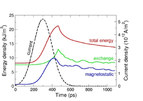
Fig. 2 shows the evolution in time of the sample’s spatially averaged energy density in the case of an applied current pulse of 5.2 A/m2 and ps. After the core switches, the total energy rapidly decreases as a consequence of the annihilation of the vortex-antivortex pair. It can clearly be seen that the exchange energy decreases after the core switching event, in agreement with the interpretation given in Ref. Hertel et al. (2006) that it is the exchange field which is ultimately driving the core reversal.
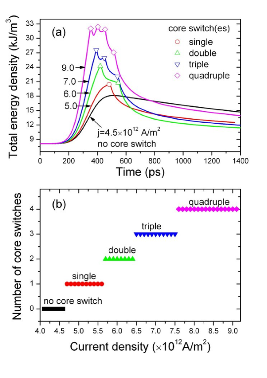
By increasing the pulse strength, it is possible to produce multiple switches, as shown in Fig. 3. Such multiple switches are a repeated series of vortex-antivortex pair creation and annihilation processes. In all cases, the total energy is seen to immediately decrease following each core reversal. However, if the energy provided by the current pulse after a core reversal is strong enough to overcompensate the energy dissipation, the energy can still increase before further switches occur. A double core switching is obtained with current pulses of about 6 A/m2, while triple and quadruple switches occur with pulses of 7 A/m2 and 9 A/m2, respectively. Ultimately, for very large currents (above 14 A/m2), the vortex core is expelled from the sample.
The diagram in Fig. 3 (b) shows the number of core switches as a function of the applied current’s strength. Clear “steps” are observed. While the core reversal mechanism is mediated by the formation of a vortex-antivortex pair, it is the annihilation process which leaves the vortex with an oppositely-polarized core. As shown in Ref. Hertel and Schneider (2006), such an annihilation is mediated by a magnetic singularity (Bloch point) which is injected through the sample. Since the energy of formation of a Bloch point is uniquely a function of the material exchange constant Tretiakov and Tchernyshyov (2007), the annihilation (and thus the reversal) process can only occur at specific energy values, resulting in the observed steps.
In conclusion, we have presented the possibility of reversing the polarization of a magnetic vortex core using short current pulses. The actual magnetization reversal process, which consists of a complicated sequence of vortex-antivortex pair creation and annihilation events, unfolds on a time scale of ca. 40 ps, i.e. shorter than the duration of the pulses applied in this study. Further investigations are required to explore the limits of the operational range for a controlled, single toggle switching in terms of pulse duration and pulse strength, and to determine how short a current pulse can be to trigger a vortex core reversal. The current-induced vortex core reversal opens the possibility of addressing individual magnetic elements in a vortex state within an array of nanoelements. This feature, in combination with the small size of magnetic vortex cores, their high thermal stability and the high speed of the reversal process could make vortex cores interesting candidates for data storage purposes in future devices.
Y.L. acknowledges financial support from the Alexander von Humboldt foundation.
References
- Cowburn et al. (1999) R. P. Cowburn, D. K. Koltsov, A. O. Adeyeye, M. E. Welland, and D. M. Tricker, Phys. Rev. Lett. 83, 1042 (1999).
- Miltat and Thiaville (2002) J. Miltat and A. Thiaville, Science 298, 555 (2002).
- Shinjo et al. (2000) T. Shinjo, T. Okuno, R. Hassdorf, K. Shigeto, and T. Ono, Science 289, 930 (2000).
- Gerrits et al. (2002) T. Gerrits, H. van den Berg, J. Hohlfeld, L. Bär, and T. Rasing, Nature 418, 509 (2002).
- Choe et al. (2004) S. B. Choe, Y. Acremann, A. Scholl, A. Bauer, A. Doran, J. Stohr, and H. A. Padmore, Science 304, 420 (2004).
- Park et al. (2003) J. P. Park, P. Eames, D. M. Engebretson, J. Berezovsky, and P. A. Crowell, Phys. Rev. B 67, 020403(R) (2003).
- Wachowiak et al. (2002) A. Wachowiak, J. Wiebe, M. Bode, O. Pietzsch, M. Morgenstern, and R. Wiesendanger, Science 298, 577 (2002).
- Van Waeyenberge et al. (2006) B. Van Waeyenberge, A. Puzic, H. Stoll, K. W. Chou, T. Tyliszczak, R. Hertel, M. Fähnle, H. Brückl, K. Rott, G. Reiss, et al., Nature 444, 461 (2006).
- Hollinger et al. (2003) R. Hollinger, A. Killinger, and U. Krey, J. Magn. Magn. Mater. 261, 178 (2003).
- Okuno et al. (2002) T. Okuno, K. Shigeto, T. Ono, K. Mibu, and T. Shinjo, J. Magn. Magn. Mater. 240, 1 (2002).
- Argyle et al. (1984) B. E. Argyle et al., Phys. Rev. Lett. 53, 190 (1984).
- (12) M. Fähnle, private communication.
- Hertel et al. (2006) R. Hertel, S. Gliga, M. Fähnle, and C. M. Schneider, cond-mat 0611668 (2006), (accepted for publication in Phys. Rev. Lett.).
- Hertel et al. (2004) R. Hertel, W. Wulfhekel, and J. Kirschner, Phys. Rev. Lett. 93, 257202 (2004).
- Zhang and Li (2004) S. Zhang and Z. Li, Phys. Rev. Lett. 93, 127204 (2004).
- Thiaville et al. (2005) A. Thiaville, Y. Nakatani, J. Miltat, and Y. Suzuki, Europhys. Lett. 69, 990 (2005).
- Kasai et al. (2006) S. Kasai, Y. Nakatani, K. Kobayashi, H. Kohno, and T. Ono, Phys. Rev. Lett. 97, 107204 (2006).
- Hertel and Schneider (2006) R. Hertel and C. M. Schneider, Phys. Rev. Lett. 97, 177202 (2006).
- Kläui et al. (2006) M. Kläui, M. Laufenberg, L. Heyne, D. Backes, U. Rüdiger, C. A. F. Vaz, J. A. C. Bland, L. J. Heyderman, S. Cherifi, A. Locatelli, et al., Appl. Phys. Lett. 88, 232507 (2006).
- Tretiakov and Tchernyshyov (2007) O. A. Tretiakov and O. Tchernyshyov, Phys. Rev. B 75, 012408 (2007).