Theory
of Optical Transmission through Elliptical Nanohole Arrays
Yakov M. Strelniker
strelnik@mail.biu.ac.il
Department of Physics, Bar-Ilan
University, 52900 Ramat-Gan, Israel
Abstract
We present a theory which explains (in the quasistatic
limit) the experimentally observed
[R. Gordon, et al,
Phys. Rev. Lett.
92, 037401 (2004)]
squared dependence of the depolarization ratio on the aspect
ratio of the holes, as well as other
features of extraordinary light transition.
We calculated the effective dielectric tensor of a
metal film penetrated by elliptical cylindrical holes
and found
the extraordinarily light transmission
at special frequencies related to the surface plasmon
resonances of the composite film.
We also propose to use the magnetic field for getting
a strong polarization effect,
which depends on the ratio of the cyclotron
to plasmon
frequencies.
pacs:
64.60.Ak,
73.23.-b; 72.80.Tm, 78.66.Sq,
77.84.Lf
A pioneering article of Ebbesen et. alEbbesen
reported on an extraordinary optical transmission through periodic
holes array in metallic films. This was explained
by the coupling of light with surface plasmons.
In most of the articlesmany1
published
after Ref. Ebbesen, ,
the surface plasmons were treated as the coupled waves,
propagating along both film surfaces
(in framework of the theory described in Ref. book, ).
In this approach the periodicity and spacing between the holes
were taken into account, but the shape of the holes was not.
In Ref. Martin,
it was even written that in “the long-wavelength
limit … the transmission coefficient …
does not appreciably depend on hole-shape”.
In contrast to this, in our
paper sb1,
we treat the plasmon as the excitations
localized around the holes single .
It was
shown that
the present of the magnetic field transforms
the initially circular holes into elliptical ones in the
re-scaled virtual coordinate
space.
That is,
it was predicted that
the elliptical shape of inclusions should
induce some anisotropy
into the system.
This prediction was apparently not known to the authors of
Ref. Gordon00, ,
who actually confirmed it in their recent experiment
on
light transmission through a periodical array
of real (not virtual) elliptical holes.
In this paper we present a theory, which in the quasistatic
(long wavelength) limit explains the
squared dependence of the depolarization ratio on the aspect
ratio of the holes (experimentally observed
in Ref. Gordon00, ),
as well as other
optical
features.
This theory is a further development
of our methods described in Refs. sb1, ; BergStrelPRL98, ; SSVAppl, .
We also note that similar effects
(e.g., light polarization) can be reached by applying a
static magnetic field.
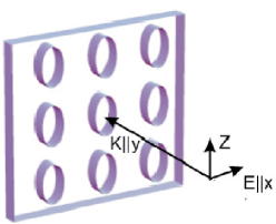
(a) (b)
Figure 1: (a) A schematic drawing of a
metal film with a periodic array of elliptical holes.
The incident light beam is normal to the film surface,
i.e., the ac
electric field is parallel to the film plane, while the wave
vector is normal to it (i.e., ).
(b)
An elliptical hole in a unit cell
when
the main semi-axes and
are inclined in
respect to the lattice axes and
by an angle .
Let us consider a geometry which corresponds to the
above-mentioned experiment Gordon00 :
a metal film with a square array of identical perpendicular
elliptical holes.
A monochromatic light beam of angular frequency
impinges upon this film along the perpendicular
axis , with linear polarization along the principal axis of the
array (see Fig. 1).
Following Refs. sb1, ; BergStrelPRL98, ; SSVAppl, ,
we can treat
the holes as
dielectric inclusions embedded in a conducting
host.
StrelBerg94 ; sb1
In this approach,
the local electric potential
is then the solution of a boundary value problem based upon the
Laplace partial
differential equation
(1)
and the boundary condition
Here is the -component of
r,
and
are the electrical permittivity tensors of the
inclusions and the metal host respectively,
,
is the characteristic
function describing the location and the shape of the inclusions
( inside the inclusions and outside
of them). StrelBerg94 ; sb1 ; Berg0
The host with the anisotropic permittivity tensor
can be transformed to
an isotropic
using
the
rescaling of the Cartesian coordinates
(.
Then
elliptic cylinder
inclusion will be transformed
into some
new
elliptic
cylinder in the rescaled virtual -space, and
the electric field
inside this
single
inclusion {inclined by some angle in
respect to the main axes [see Fig. 1(b)]}
can be found from the system
of linear equations mg2 ; BergStrelDualityPRB98
(2)
where
are the Cartesian components of the depolarization factor
mg2 ; BergStrelDualityPRB98 .
The latter
can be transformed to the diagonal form
by a simple
coordinate rotation
,
where is the angle on inclination of the elliptical holes
from the lattice axes [see Fig. 1(b)],
is the rotation matrix
(3)
which directs the new
coordinate axes
along the principal ellipse
axes.
Note that (as well as )
now
depends on the precise shape of the transformed inclusion,
and therefore is a function
of .
If the coordinate axes are the principal axes of the inclusion
(), then
the elliptic cylindric hole
of the semi-axes
and (with symmetry axis along )
transforms in -space into a new elliptic cylinder
with semi-axes
and
for which:
(4)
(5)
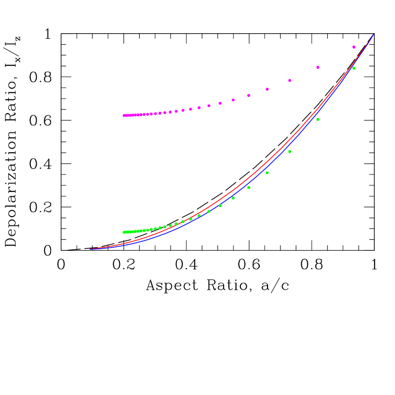
Figure 2: (Color online)
The depolarization ratio of the transmitted
light as a function of the aspect ratio of the holes
for different .
For the values of
from nm
to nm
the curves are close enough to the square law
(left dashed
curve),
while already for nm and nm
(shown by dotted lines)
the polarization ratio is
essentially different
from this
law.
For simplicity, we assume the host permittivity tensor
has the form , where
the
conductivity tensor
is taken in the free-electron
Drude approximation with :
(9)
is the scalar dielectric constant of the
background ionic lattice, and is the unit tensor.
The magnetic field enters only through the Hall-to-Ohmic resistivity ratio
,
where is the cyclotron frequency,
is the conductivity relaxation time,
is the plasma frequency,
is
the charge carrier concentration,
is its effective mass, and is the Hall mobility.
When (),
we have , .
However, when the depolarization factor
has a complicated dependence on .
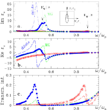
Figure 3: (Color online)
Transmission spectrum through an elliptical
nanohole arrays for the
- and - linear light polarizations.
The polarization is parallel to the [0,1] direction,
while is parallel to the [1,0] direction.
(a) Im
(, polarization)
and Im
(, -polarization)
vs. .
(b) Re
and Re vs. .
In both polarizations
there is an SP resonance peak
at and
(shown by the arrow), respectively. When
, the
resonance shifts for larger values
and its amplitude reduces drastically.
(c) Transmission coefficient
vs. frequency ,
for different polarizations
and .
The analytical results obtained using a dilute and
MG approximations
are
indicated by
dashed
curves. The
(connected by lines)
filled
and open
symbols
denote the results obtained
numericallyStrelBerg94
for a square array of holes in the shape of elliptical
cylinders.
Inset
to Fig. (a): a unit cell with the elliptic hole
and
coordinate axes.
Solving the system of linear equations
(2), we obtain the
following expression for the uniform electric field inside the original
elliptical cylinder
(when ):
(10)
where is a matrix
whose nonzero components are:
,
,
,
.
From Eq. (10) it follows
that
the depolarization ratio [i.e., the ratio of the light intensity
(polarized parallel to -axis) to the light intensity
(polarized parallel to -axis), and therefore
proportional to
],
can be written (in the case of
) as
(11)
Let us consider
the case of zero magnetic field, , when
both the host and the inclusions are
isotropic
and, therefore,
are characterized by
the scalar tensors ,
(where is a unit matrix).
We assume also that
.
When
and ,
what might be true in the simple limit
and
with
(situation of
Ref. Gordon00, ),
then from
Eq. (11) it follows that
In Fig. 2 we show the
ratio (11)
for different wave-lengths, . Using the dataHass
of the complex permittivity
of the evaporated gold,
we can see that
in the wave-length’s range between
nm
()
and nm
(),
the curves are close enough to the
law
,
while already for nm (for which ,
the polarization ratio
(shown by the dotted line)
is essentially different
from this
law.
If and , then
(see Eq. 11).
In Drude approximation (9)
(and in the limit ,
)
this
takes the simplest form
(13)
from which it follows that the depolarization ratio
can be made arbitrarily large,
since
the value
[where
see comments to Eq. (9)],
can be made
as close to 1 as necessary.
Next, we approximately compute the tensor ,
which
is defined by the relation
where denotes a volume average, and
is the local dielectric tensor.
In the case
of the dilute collection
of the
elliptic cylinders,
the
tensor takes the formStrelBerg94 ; sb1 ; Berg0
where is the volume fraction of inclusions. For the
case
(and
when and
the coordinate axes are
directed
along the
symmetry axes of the ellipse),
takes the form
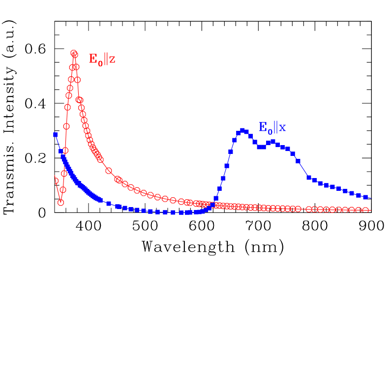
Figure 4: (Color online)
The same as Fig. 3(c), but vs. wavelength
.
The peak at corresponds
to (i.e., -) polarization (shown in Fig. 2 of Ref. Gordon00, ),
while the peak at corresponds
to polarization
(not shown in Fig. 2 of Ref. Gordon00, ).
.
The
frequency of the surface plasmon
(SP) polarized
in the direction is
the one in which
[see Eq. (10) and Eq. (14)]
becomes very large even for
a very small applied field.
This condition is satisfied when
Substituting Eq. (9) into this,
and
letting , one obtains
(15)
For this simplifies into
.
In Maxwell-Garnett (MG) or Clausius-Mossotti
approximationBerg0 ,
expressions for and
can be obtained directly
from
Eqs. (14),(15),
obtained in dilute approximation
just by formal substitution
.SSVAppl
When the aspect ratio tends to infinity
the considered geometry transforms
into the case of the parallel slabs,
which can be solved exactly:
Using the form
(9),
we can find
the resonance frequency
This coincides with Eq. (15) in the limit .
The other exact solvable geometry, parallel cylinders,
for which ,
does not give any resonance:
.
When the cylindrical holes are arranged on a two-dimensional periodic
latticeEbbesen ; Gordon00
a more suitable approach is
a Fourier expansion
technique
StrelBerg94 .
Since and
are now periodical functions,
they can be
expanded
in a Fourier series.
This transforms Eq. (1) into an infinite set of linear
algebraic equations for the Fourier coefficients
,
where
is a vector of the appropriate reciprocal lattice,
are the arbitrary integers, is a lattice constant,
and is the volume of a unit cell.
After solving a truncated,
finite subset of those equations,
we can use those Fourier coefficients
in order to calculate the bulk effective
macroscopic electric permittivity tensor ,
using the procedure
described in Ref. StrelBerg94, ; sb1, ; Berg0, .
Note that the Fourier
coefficient
of the -function of the elliptical
hole (inclined
by the angle in respect
to the main lattice axes) has the formStrelBerg94 ; sb1
where is a Bessel function and
.
In Figs. 3(a) and 3(b) we show
the
imaginary and real parts of
vs. , respectively.
The
curves without
points are the two principal in-plain components
and
(corresponding to polarizations
and , respectively)
as obtained in the dilute
and MG approximation.
The full
and open squares
in Fig. 3(a) denote the same quantities,
but now for a square lattice (of
lattice constant )
of elliptical
holes with the same
aspect ratio
and volume fraction
as in MG and dilute approximations.
In this case,
and
are calculated by the Fourier expansion
techniquesb1 mentioned above.
Finally,
in Fig. 3(c), we show the calculated transmission coefficient
for the dielectric functions shown in Figs. 3(a) and 3(b).
The dependence of the transmission coefficient on frequency ,
[as well as on the wave length (see Fig. 4)]
for different
film thicknesses, can be obtained from the
effective value
using the known expression LandauLif
for , where
, and
, ,
,
and is the
film thickness.SSVAppl
The transmission coefficient
[see Fig. 3(c)]
shows the characteristic “extraordinary
transmission” peaks expected, based on Figs. 3(a),(b).
Since
the angular dependence of the permittivity tensor
in the rotated coordinate system
[where is given by Eq. (3) and
is the polarization angle i.e., the angle between the
vector and the axes of the ellipse,
see Fig. 1(b)]
is
a cosine-like
[e.g.,
], the angular dependence of the transmission
coefficient looks
(depending on the values of
and ) also
as a cosine-like.
This
explains the Malus’ lawDiMaio
of the light transmission, ,
observed in Refs. Gordon00, ; DiMaio, .
The
amplitudes and frequencies
of the peaks (for both polarizations and
)
depend
on the aspect-ration . For polarization along axis
the resonance frequency shifts for larger value
and its amplitude reduces drastically.
Estimating the imaginary part
of
[see Eq. (14)]
at the resonance frequency
, we found
that the ratio
Im Im
is of the order .
For
the aspect ratio
this is of the order ,
in agreement with our numerical calculations
[see Fig. 3(a)].
One might expect that in the extraordinary light transition
the maximum at will also be much smaller when
compared to the maximum at ,
but [as we can see in Figs. 3(c) and 4],
they are of the same order.
In Fig. 4 we show the data, presented in Fig. 3(c),
in terms of wavelength .
The calculations were performed
for the systems with
aspect ratio
, volume
fraction of holes, , ,
,
(a typical for Au value Gordon00 ,
so that ),
,
,
and the film thickness .
In summary, we have studied analytically and
numerically
the extraordinary transmission through
perforated metal films with elliptical holes.
We have explained analytically the optical features
found experimentally and described
in Ref. Gordon00, . Our numerical results are
in good agreement with experimental data.
We also propose to use the magnetic field for
getting a strong polarization effect,
which depends on the ratio
.
As a material which may be
suitable for this purpose
the bismuth
can be considered,
where
the low carrier density
( cm-1) can make
the carrier
cyclotron energies, ,
equal to or greater
than
the plasmon energy, .
Sherriff
We thankfully acknowledge useful conversations with David J. Bergman
and Nilly Madar.
This research was supported in part by grants from the
Israel Science Foundation,
and
the KAMEA Fellowship program of the
Ministry of Absorption of the State of Israel.
References
(1)
T.W. Ebbesen, H. J. Lezec, H. F. Ghaemi, T. Thio,
and P. A.Wolff, Nature (London) 391, 667 (1998).
(2)
A. Garcia-Martin, G. Armelles, and S. Pereira,
Phys. Rev. B 71, 205116 (2005),
and references therein.
(3) H. Raether, Surface Plasmons
(Springer-Verlag, Berlin, 1988).
(4)
L. Martin-Moreno,
et al,
Phys. Rev. Lett. 86, 1114 (1998).
(5) Y. M. Strelniker and D. J. Bergman, Phys. Rev. B 59, R12763 (1999).
(6) The experimental observation of a plasmon localized
around a
single hole
see e.g. in
L. Yin et al, Appl. Phys. Lett.
85, 467 (2004),
A. Degiron, H. J. Lezec, and N. Yamamoto, and T. W. Ebbesen
Opt. Commun. 239, 61 (2004),
C. Genet and T. W. Ebbesen, Nature
445, 39 (2007), and references therein.
(7)
R. Gordon,
A.G. Brolo,
A. McKinnon, A. Rajora, B. Leathem, and K. L. Kavanagh,
Phys. Rev. Lett. 92, 037401 (2004).
(8) D. J. Bergman and Y. M. Strelniker,
Phys. Rev. Lett. 80, 857 (1998);
Y. M. Strelniker and D. J. Bergman,
Eur. Phys. J. AP 7, 19 (1999).
D. J. Bergman and Y. M. Strelniker, Physica B 279, 1 (2000).
(9)
Y. M. Strelniker,
D. Stroud,
and A. O. Voznesenskaya,
Eur. Phys. J. B 52, 1 (2006);
J. Appl. Phys. 99, 08H702 (2006).
(10) Y. M. Strelniker and D. J. Bergman,
Phys. Rev. B 50, 14001 (1994);
D. J. Bergman and Y. M. Strelniker, Phys. Rev. B 49, 16256
(1994).
(11)
D. J. Bergman and D. Stroud, Solid State Physics 45, 147 (1992);
G. W. Milton, in The Theory of Composites
(Cambridge, 2002).
(12)
D. J. Bergman and Y. M. Strelniker,
Phys. Rev. B 60, 13016 (1999).
(13)
D. J. Bergman and Y. M. Strelniker,
Phys. Rev. B 59, 2180
(1999).
(14)
L. D. Landau, E. M. Lifshitz, and L. P. Pitaevskii,
Electrodynamics of Continuous Media (Pergamon Press,
Oxford, 1984).
(15) G. Hass, L. Hadley,
Optical Properties of Metals, pp. 6-133,
in American Institute of Physics Handbook,
Third Edition, New York, by ed. D. E. Gray.
(16) J. R. DiMaio and J. Ballato,
Optics Express 14, 2380 (2006).
(17) R. E. Sherriff and R. P. Devaty,
Phys. Rev. B 41, 1340 (1990);
Phys. Rev. B 48, 1525 (1993);
L. M. Claessen,
A. G. Jansen, and P. Wyder, Phys. Rev. B 33, 7947 (1986);
G. J. Strijkers, et al,
IEEE T MAGN 37,
2067 (2001).