Swapping trajectories: a new wall-induced cross-streamline particle migration mechanism in a dilute suspension of spheres
Abstract
Binary encounters between spherical particles in shear flow are studied for a system bounded by a single planar wall or two parallel planar walls under creeping flow conditions. We show that wall proximity gives rise to a new class of binary trajectories resulting in cross-streamline migration of the particles. The spheres on these new trajectories do not pass each other (as they would in free space) but instead they swap their cross-streamline positions. To determine the significance of the wall-induced particle migration, we have evaluated the hydrodynamic self-diffusion coefficient associated with a sequence of uncorrelated particle displacements due to binary particle encounters. The results of our calculations quantitatively agree with the experimental value obtained by Zarraga & Leighton (2002) for the self-diffusivity in a dilute suspension of spheres undergoing shear flow in a Couette device. We thus show that the wall-induced cross-streamline particle migration is the source of the anomalously large self-diffusivity revealed by their experiments.
1 Introduction
Random displacements resulting from particle encounters in suspension flows lead to hydrodynamically induced particle migration with respect to the local suspension velocity (Eckstein et al., 1977; Leighton & Acrivos, 1987; Bossis & Brady, 1987). For non-Brownian particles under creeping-flow conditions, hydrodynamically induced migration constitutes an important mechanism of particle redistribution in the suspending fluid. Thus studies of particle encounters in flowing suspensions are vital both from the fundamental and practical points of view.
As shown by Batchelor & Green (1972), two spheres passing each other in unbounded shear flow return to the initial transverse (cross-streamline) positions after a binary encounter is completed. This behavior follows from the flow reflection symmetry of Stokes equations and a reflection symmetry of the system. Since on open binary trajectories there are no cross-streamline particle displacements, for perfect spheres in free space the transverse hydrodynamic-diffusion process requires encounters of at least three particles (see, eg. Acrivos, Batchelor, Hinch, Koch & Mauri, 1992; Wang, Mauri & Acrivos, 1996, 1998; Drazer, Koplik, Khusid & Acrivos, 2002). It follows that the self-diffusion coefficient scales as in the low-concentration regime, and the contribution associated with binary encounters arises only in the presence of non-hydrodynamic forces that remove the flow-reflection symmetry of the problem. For non-Brownian particles non-hydrodynamic interactions often result from direct particle contacts due to surface roughness.
Several years ago Zarraga & Leighton (2002) measured the contribution to the shear-induced self-diffusivity for a dilute suspension of spheres undergoing shear flow in a Couette device. The experiments yielded a surprising result: the self-diffusion coefficient was nearly an order of magnitude higher than the theoretical estimate (da Cunha & Hinch, 1996; Zarraga & Leighton, 2001) for rough spheres with the roughness amplitude corresponding to the experimental system. Several possible causes of the anomalous self-diffusivity (such as inertial lift and non-Newtonian effects) were examined, but none of them was sufficient to explain the anomaly.
The suspension in the Couette device used in experiments of Zarraga & Leighton (2002) was bounded by nearly flat parallel walls separated by a relatively small distance (where is the particle diameter). In the analysis of experimental results it was assumed that the effect of walls on the self-diffusivity coefficient must be negligible. Since the fore-aft symmetry of the system would ensure that after passing each other the particles would return to their original streamlines (as they do in infinite space), it seemed unlikely that the walls were the cause of the enhanced self-diffusivity.
In the present paper we show that hydrodynamic interactions of particle pairs with the confining walls result in cross-streamline particle displacements in binary encounters in shear flow. Specifically, we have found a new class of binary trajectories: the particles on such trajectories initially approach each other, but then they move across the channel in opposite directions and separate without passing each other (unlike the particles in free space).
The new class of trajectories results from a sign change of the transverse component of the relative particle velocity. Such sign changes in wall-bounded systems were first pointed out in our recent study (Bhattacharya, Bławzdziewicz & Wajnryb, 2005a). Thus seemingly subtle features of particle mobilities produce a significant qualitative effect: our explicit calculations show that after the new class of particle trajectories is included in an estimate for the shear-induced self-diffusivity, a quantitative agreement is obtained between the measurements of Zarraga & Leighton (2002) and theoretical predictions. Hence, the paradox of the unusually large self-diffusivity observed by Zarraga & Leighton (2002) has been resolved.
The system considered in our paper is defined in section 2. The new class of binary trajectories resulting in cross-streamline particle displacements and the physical mechanism leading to this behavior is discussed in section 3. In section 4 we analyze the consequences of the new pair trajectories for cross-streamline particle migration in suspensions of spheres in the low-concentration regime. Our findings are summarized in section 5.

2 Definition of the system
We consider the dynamics of binary encounters of spherical particles undergoing stationary shear flow in a space bounded by a single planar wall or two parallel planar walls separated by the distance . We focus on configurations where the particle–wall separation is comparable to the sphere diameter . The suspending fluid has viscosity , and creeping flow conditions are assumed.
We use a coordinate system where the walls are in the – planes. The positions of particle centers are denoted by and the linear and angular velocities of the particles by and , respectively, where . The walls are at and . Particle encounters are described using the relative coordinates , where
| (1) |
is the relative position vector centered on particle .
The unperturbed fluid velocity
| (2) |
(where denotes the shear rate) points in the lateral direction , and varies in the normal direction . The flow occurs due to the motion of the upper wall with velocity
| (3) |
Particles are torque and force free. No-slip boundary conditions are imposed at both walls and at the particle surfaces.
In our calculations of particle trajectories, interparticle and particle–wall hydrodynamic interactions are accurately taken into account. For a one-wall system the particle velocities are evaluated using a reflection technique (Cichocki et al., 2000), and for the two-wall system we use the Cartesian-representation method, recently developed by our group (Bhattacharya et al., 2005b, a, 2006a). The equations of motion (where the dot denotes the time derivative) are integrated using a Runge-Kutta algorithm with an adaptive time step (Press et al., 1992).
The geometry of the system and a sketch of trajectories for two spheres that pass each other are shown in figure 1. The trajectories in this figure are out of scale, and an accurate representation of the trajectories can be seen in figure 2.
3 Effect of walls on the dynamics of binary collisions
3.1 The morphology of open trajectories
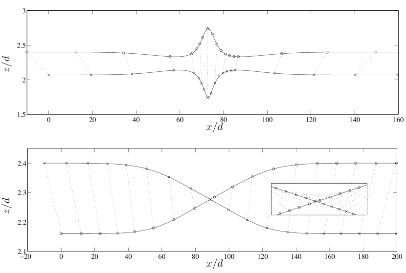
An analysis (Lin, Lee & Sather, 1970; Batchelor & Green, 1972; Zinchenko, 1984) of the relative motion of a pair of spheres in unbounded shear flow (2) indicates that all open trajectories start from and extend to (in a reference frame fixed on the initially slower particle 1). During the approach of the particles their relative vertical offset increases, reaching a maximum when the particle pair crosses the vorticity–gradient plane . However, after the particles have separated, they return to their initial cross-streamline positions , in accordance with the flow-reversal symmetry of Stokes equations and the symmetry of the system with respect to the reflection of the coordinate.
For sufficiently large initial vertical offsets particle trajectories in wall-bounded systems are qualitatively similar to those in free space. The only distinctive feature of the trajectory depicted in the top panel of figure 2 is that decreases before reaching the maximum for the particle pair in the symmetry plane , while in free space would increase monotonically.
However, for smaller initial values of we find an entirely different behavior: for the new kind of open trajectories shown in the bottom panel of figure 2 the offset changes sign before the relative position has been reached. Accordingly, the component of the relative velocity
| (4) |
also changes sign. The particles do not pass each other – they turn around and separate, maintaining for the whole trajectory. As a result, the spheres do not return to their initial streamlines at long times but instead they swap their vertical coordinates . Such particle encounters result, therefore, in displacements of the suspended particles across streamlines of the external flow.
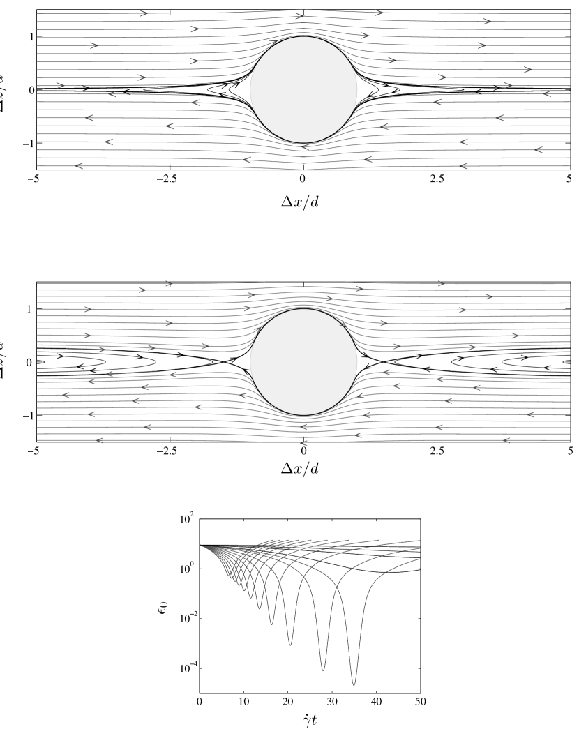
The difference in topology of pair trajectories in unbounded space and in a parallel-wall channel is clearly seen in figure 3, where the relative particle motion is depicted in the reference frame centered on one of the particles. In free space (top panel) the contact surface is surrounded by an envelope of closed orbits, and all open trajectories correspond to particles passing each other. In contrast, in the wall-bounded system (middle panel) there also exists a region of swapping trajectories, delimited by the critical trajectories crossing the plane at the points where .
We emphasize that the swapping trajectories do not violate any symmetries of the system. Since the particles do not pass each other, individual trajectories are not symmetric with respect to the reflection . However, for each trajectory in the halfspace there is a corresponding reflected trajectory in the halfspace .
The position-swapping trajectories have several important consequences. First, they contribute to cross-streamline particle migration in dilute suspensions bounded by planar or nearly planar walls. In particular, this migration mechanism explains the enhanced hydrodynamic self-diffusivity observed by Zarraga & Leighton (2002), as discussed in section 4.
Another important consequence of the swapping mechanism is that it prevents near-contact particle encounters. The results depicted in the middle panel of figure 3 indicate that spheres on the swapping trajectories approach each other less closely than spheres on the usual trajectories (i.e. when the particles pass each other). A detailed view of the evolution of the dimensionless gap between the particles,
| (5) |
is shown in the bottom panel of figure 3. The results (shown for each of the trajectories displayed in the middle panel) indicate that the gap on non-swapping trajectories may decrease to about , whereas on the swapping trajectories always remains of order one. Thus, the swapping mechanism may prevent particle aggregation in the presence of short-range attractive forces.
3.2 Mechanism for particle swapping
As shown in the middle panel of figure 3, the swapping trajectories occur when the vertical component of the relative particle velocity (4) is negative in a subdomain of particle configuration with and positive in the corresponding subdomain of the region . Consider, for example, a pair of spheres located in a flow–vorticity plane , and assume that , i.e., sphere 1 is to the left of sphere 2. If in this configuration, sphere 2 moves from the region below sphere 1 (where ) to the region above sphere 1 (where ). Thus, the particles initially approach each other but then they separate without passing each other – they swap their vertical positions instead.
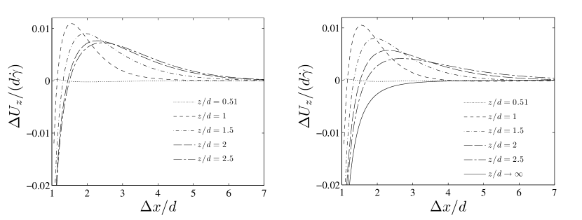
The dependence of the relative vertical velocity on particle separation is depicted in figure 4 for a particle pair aligned in the flow direction. The results indicate that in wall-bounded systems the relative vertical particle velocity changes sign at a critical particle separation that depends on the channel width and the position of the particles with respect to the walls of the channel. For the sign of is consistent with the topology of the swapping trajectories, and for the sign of corresponds to closed orbits. No such sign change, however, occurs in free space.
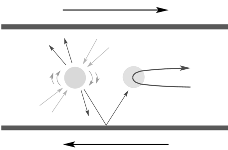
Although particle behavior on swapping trajectories seems at first counterintuitive (the vector connecting the particle centers rotates with an angular velocity opposite to the vorticity of the external flow) it can be qualitatively explained by considering an analogy with shear flow in a channel blocked by an obstacle. If the channel is completely blocked, the fluid dragged by a wall towards the obstacle is deflected to the other side of the channel and returns along the opposite wall. If the channel is partly blocked (by one of the spheres in our system) the streamlines that directly approach the obstacle are deflected and exhibit the recirculation behavior. Analogously, in a two-sphere system the swapping motion of each particle is produced by the flow deflected by the other particle.
A more detailed, quantitative explanation of the swapping mechanism is obtained by analyzing the effect of the walls on the flow pattern around a single sphere in shear flow in a weakly confined system. To leading order in the particle–particle and particle–wall separations, the fluid velocity and the velocity of the second particle are identical. Therefore, for weak confinements the comparison of the particle and fluid velocities has a quantitative meaning (assuming that the interparticle distance remains sufficiently large), and for strongly confined systems, pair trajectories are expected to qualitatively resemble the streamlines of .
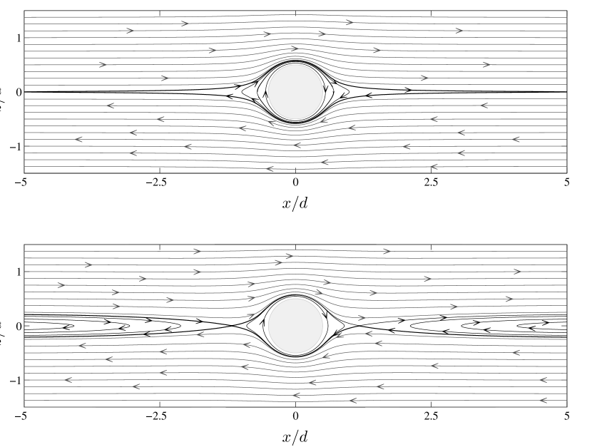
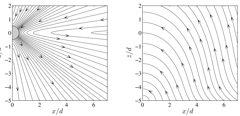
The flow pattern around a single force- and torque-free sphere in an unbounded and in a wall-bounded shear flow is illustrated in figure 5. The streamlines are depicted in a the coordinate system centered on the particle. The top panel shows the familiar velocity field for a particle in free space, and the bottom panel represents the corresponding flow for a sphere in the middle of a channel with wall separation . As expected, in the wall-bounded system there is a region of recirculating streamlines analogous to the swapping trajectories shown in figure 3.
The hydrodynamic mechanism that leads to the recirculating streamlines (and hence to the particle position-swapping) can be explained by examining the wall reflection of the perturbation flow produced by a sphere in external shear flow, as schematically represented in figure 6. Only the reflection from the lower wall will be discussed because the upper wall produces an analogous effect. In our analysis we assume that the wall is in the plane and the particle is at , where .
The perturbation flow that results from the scattering of the external flow (2) by the sphere can be expressed by the formula (Kim & Karrila, 1991)
| (6) |
where (with ) is the position of a field point with respect to the particle center, , and . The flow is a superposition of the radial stresslet contribution (the first term on the right-hand side of the above equation) and the potential contribution (the second term).
The streamlines of the perturbation velocity field (6) are shown in the left panel of figure 7 for a system with particle-wall separation . In the plane (the horizontal plane passing through the particle center), the radial stresslet contribution vanishes, and the shorter-range potential-flow contribution is vertical, with an orientation consistent with the vorticity of the external flow.
Relation (6) indicates that at the wall surface (i.e. the plane ) the perturbation flow points downwards for and upwards for . To ensure that there is no fluid flux through the wall, the flow reflected from the wall, , must point in the opposite direction. Therefore, assuming that the vertical component of is a monotonic function of (at least up to the particle position), we find that the reflected flow has the direction needed to produce the recirculating streamlines (cf. figure 6).
It can be shown that decays as with the distance from the image singularity at (the image flow involves the reflection of the stresslet). It follows that for the flow dominates the oppositely directed potential-flow term of , except in the region near the particle. This behavior is consistent with the pattern of the streamlines depicted in the bottom panel of figure 5 and with the topology of pair trajectories represented in the middle panel of figure 3.
The above essential features of the reflected flow can be explicitly seen for a simple case of free interface. To the leading order in , the flow reflected from such an interface is given by the expression
| (7) |
where and denote the coordinate and position vector in the reference frame centered at the image singularity. Note that for positions close to the particle, the magnitude of the flow (7) is , because both and .
For rigid walls, the crucial features of the reflected flow (i.e., the direction consistent with the swapping particle motion, the overall decay, and the small additional factor for near the plane ) can be derived using Lorentz (1907) reflection formula, as discussed in Appendix A. These features can also be seen from the streamlines of depicted in the right panel of figure 7.
In the above analysis of the particle-swapping mechanism we have focused on a single reflection of the perturbation flow from a wall. However, complete multi-body hydrodynamic particle interactions in wall presence are accurately accounted for in our quantitative calculations. While our paper is focused on particle motion in the creeping flow regime we would also like to note that fluid reversal zones and position-swapping pair trajectories similar to those seen in figures 3 and 5 were observed at finite Reynolds numbers for unconfined configurations (Mikulencak & Morris, 2004; Subramanian & L., 2006; Kulkarni-Morris, 2007).
3.3 The domain of swapping trajectories
A pair of particles on a swapping trajectory crosses the horizontal plane in the direction corresponding to the counter-rotation of the vector connecting the particle centers (cf. section 3.2). Since the counter-rotation ceases at the points where changes sign, the region of swapping trajectories is delimited by a set of critical trajectories for which when the particle pair approaches the plane . (We note that for the condition implies that because the horizontal components of the relative velocity (4) vanish because the symmetry of the problem.)
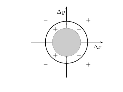
For a two-wall system a typical graph showing the sign of the vertical relative velocity and the location of points where in the flow–vorticity plane is presented in figure 8. The set of points where vanishes consists of two subsets. One is the line in the region with no particle overlap, and the other is the circle (where denotes the horizontal relative position vector, , and is the circle radius). The critical interparticle distance does not depend on the orientation of the particle pair in the plane due to symmetry (cf. explanation in Appendix B).
By analyzing the direction of sphere motion, one can show that the area inside the circle of zeros corresponds to closed trajectories passing through the plane . Therefore, only the part of the line outside this circle is associated with the critical trajectories that delimit the swapping region. We note that closed orbits also exist in unbounded shear flow (Batchelor & Green, 1972). In this case the whole surface corresponds to particle pairs on closed trajectories (as in the top panel of figure 3).
For weakly confined systems the location of zeros of results from the balance between the potential-flow contribution in equation (6) and the wall reflection of the stresslet. As already indicated in section 3.2 (cf. also Appendix A), the leading-order behavior of the vertical component of the reflected flow in the region near the particle is
| (8) |
Thus, for a fixed position of the particle pair in the channel we find that
| (9) |
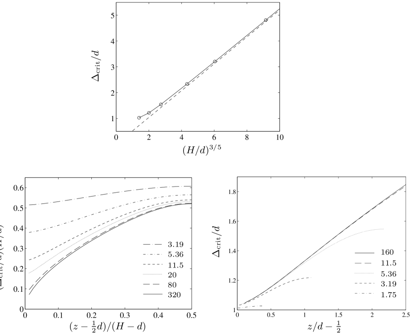
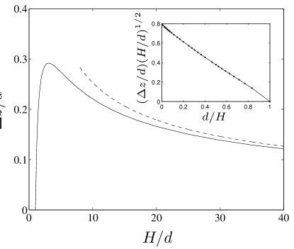
The dependence of the radius on the channel width for a particle pair in the midplane is plotted along with the asymptotic behavior (9) in the top panel of figure 9. The two bottom panels of figure 9 show the dependence of on the position of the particle pair with respect to the channel walls for different . The results represented in the left panel correspond to larger values of , and they are rescaled to emphasize the asymptotic behavior (9). In the right panel the results are shown unscaled for moderate values of . Note that for sufficiently small values of the unscaled curves corresponding to different channel widths coincide, which indicates that the particle mobility is dominated by the single-wall contribution except for particles close to the center of the channel.
An alternative way of characterizing the domain of swapping trajectories is to show the corresponding upstream region of the transverse relative coordinates , i.e., the region through which the swapping trajectories pass in the limit of infinite streamwise particle separations . For trajectories that cross a given horizontal plane during the particle motion, the border of the upstream region can be determined by integrating the trajectories backwards, starting near the loci of zeros of in the plane .
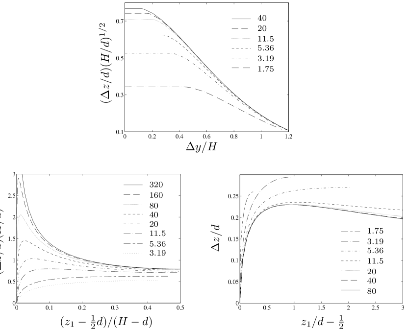
In figure 10 the upstream boundaries of the swapping-trajectory regions are shown for several values of the wall separation . The top panel depicts these boundaries for the trajectories that are symmetric with respect to the midplane (strictly speaking, symmetric with respect to the axis defined by the intersection of the planes and ). The bottom panels illustrate the dependence of the vertical extent of the upstream regions on the initial position of the lower particle for particle pairs moving in the flow–gradient plane . In all the panels the swapping-trajectory domains correspond to the areas below the curves.
By the scaling argument outlined in Appendix C, one can show that the vertical extent of the upstream swapping-trajectory region scales as
| (10) |
which is confirmed by the results shown in figure 11. The vertical axes of the plots shown in the top and left bottom panels of figure 10 are scaled accordingly, to collapse the results for large values of onto the asymptotic master curves. The results in the right bottom panel are shown unscaled to emphasize the near-wall behavior of the swapping trajectory domain.
An interesting feature of the swapping-trajectory regions shown in the top panel of figure 10 is that these domains are delimited by straight horizontal lines for . The straight-line sections correspond to the trajectories that pass through the circle of zeros of the vertical relative velocity when the particle pair crosses the horizontal plane . The remaining portions of the upstream borders of the swapping-trajectory regions correspond to the zeros of located at the axis in the plane (cf. the geometry of zeros of depicted in figure 8). The upstream coordinate in the region is independent of the corresponding position along the circle of zeros of for the same reason why does not depend on the orientation angle (cf. Appendix B).
The results in the top panel of figure 10 indicate that the lateral extent of the upstream swapping-trajectory region (normalized by the wall separation ) remains approximately constant when the wall separation increases. However, the horizontal coordinate of the end point of the straight-line section decreases, as required by the scaling (9).
We conclude this section by discussing the distance of minimal interparticle approach for pairs of spheres on swapping and non-swapping trajectories. As we have already indicated, the interparticle gap (5) on trajectories of the swapping kind typically remains relatively large. For spheres that pass through a given horizontal plane , the minimal interparticle separation on swapping trajectories coincides with the radius of the circle of zeros of the relative transverse velocity . According to the results shown in the top panel of figure 9, is typically well above the particle diameter (except for very small particle–wall separations). Thus, the minimal interparticle gap is usually . In contrast, the minimal interparticle gap on non-swapping open trajectories may be smaller by several orders of magnitude. The sharp transition from the large gaps on the swapping trajectories to much smaller values of on the nearby non-swapping ones is illustrated in the bottom panel of figure 3.
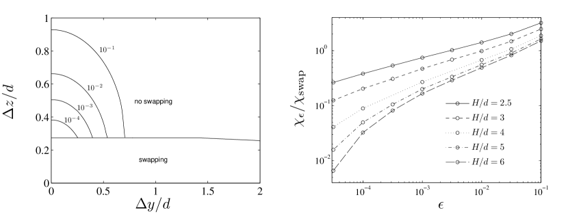
The domains of non-swapping trajectories corresponding to specific values of the minimal gap are depicted in the left panel of figure 12 for a system with a wall separation and particles moving symmetrically with respect to the midplane . The results indicate that the smallest values of the minimal gap are attained for near-critical non-swapping trajectories in the flow–gradient plane . According to our additional calculations the minimal gap decreases for stronger confinements, although it typically remains comparable to the distance of minimal approach for two spheres on open trajectories in the unbounded shear flow (Arp & Mason, 1977).
In a system of spheres interacting via a short-range repulsive potential, the near-contact particle encounters may result in cross-streamline particle displacements. However, for moderate-width channels, the upstream region corresponding to very small gaps is significantly smaller than the upstream region of swapping trajectories.
Quantitatively, the rate of particle encounters of a given type can be evaluated by integrating the upstream relative particle velocity over the appropriate upstream-coordinate region. The ratio between the rates of near-contact and swapping collisions for trajectories symmetric with respect to the midplane is plotted in the right panel of figure 12 versus the cutoff value of the minimal gap for channels of different width. The results indicate that for sufficiently small values of the gap, especially at moderate confinements.
4 Particle migration due to position-swapping binary encounters
As shown above, the position-swapping particle encounters result in cross-streamline particle migration in suspensions confined by planar (or nearly planar) walls. Although this migration mechanism may be dominant in dilute suspensions under moderate-confinement conditions, it has never been described. In this section we present our quantitative predictions for migration of spherical particles in parallel wall channels.
4.1 Population-balance simulations
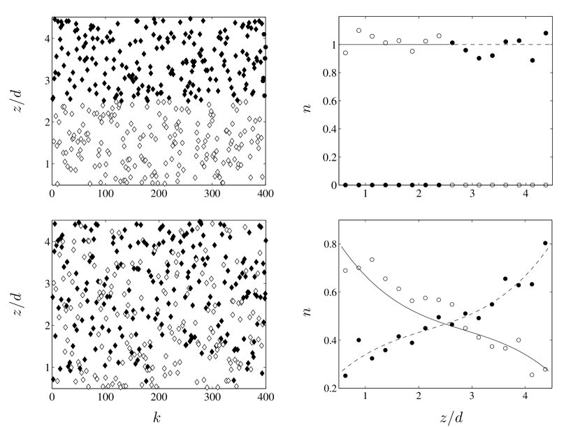
In order to illustrate the role of particle swapping in suspension flows, we have performed a population-balance simulation of a mixture of two species of equal-size spheres in a parallel-wall channel of width . Initially, the particles of species one are located in the upper portion of the channel, , and the particles of species two in the lower portion . In each part of the channel the particles are distributed randomly. Since the system is translationally invariant in the transverse directions and , the particle distribution is characterized only by the vertical coordinate .
To mimic the evolution of a dilute suspension, the particle population is updated using a Boltzmann–Monte Carlo technique. Accordingly, a pair of particles is chosen randomly from the ensemble representing the system, with a probability proportional to the upstream relative velocity . Then, a two-particle evolution run is performed with a large initial offset in the streamwise direction and the transverse offset chosen randomly from the uniform probability distribution truncated at . If the pair evolution results in position swapping, the particle ensemble is updated accordingly.
Sample results of our population-balance simulations are presented in figure 13. The calculations were performed using a set of 600 particles, and the average over seven simulation runs was taken to reduce statistical fluctuations. The top panels show the initial random particle distribution, and the bottom panels the distribution after 128 swapping collisions per particle. In the left panels the distribution is depicted by plotting the vertical positions of 400 randomly chosen particles versus particle index. The right panels represent the corresponding particle density (normalized to unity) as a function of the position across the channel. The results indicate that the two particle species slowly mix together due to the particle-swapping phenomenon. Without particle swapping, all spheres would preserve their initial vertical positions (unless non-hydrodynamic interparticle forces are present).
4.2 Self-diffusion coefficient
Assuming that the wall separation is much larger than the swapping range , a sequence of uncorrelated particle displacements due to binary encounters in suspension flow can be approximately described as a diffusion process. In this section we focus on the transverse diffusivity of a tagged particle in a dilute suspension of mechanically identical spheres.
As shown by da Cunha & Hinch (1996) in their paper on the shear-induced self-diffusivity in a dilute suspension of rough spheres (also see Zarraga & Leighton, 2001), the transverse (cross-streamline) self-diffusion coefficient , can be evaluated from the relation
| (11) |
where the integration is over the upstream region of transverse relative coordinates corresponding to particle encounters of a given type (e.g., swapping or direct particle collisions), is the particle number density and is the cross-streamline displacement of the particle during a binary-encounter event.
Since initially the particles are well separated in the streamline direction, the relative upstream velocity is the difference of the velocities of individual, non-interacting spheres at the positions and with respect to the channel walls. For particles far from the walls we simply have . More generally, assuming that the initial particle offset is sufficiently small, the relative particle velocity can be expressed as
| (12) |
where
| (13) |
is the dimensionless derivative of the velocity of an individual sphere with respect to its transverse position in the channel. According to our results (Zurita-Gotor et al., 2007), the velocity of a single sphere undergoing shear flow in a parallel-wall channel differs very little from the local fluid velocity (2), except when the particle is in the immediate wall proximity. Therefore, the approximation is often sufficient.
Particles on swapping trajectories exchange their vertical positions, which implies that the particle displacement equals the upstream offset of the particles in the interacting pair. Using the above result and relation (12), the integral with respect to in equation (11) can be explicitly performed over the swapping trajectory region. The effective self-diffusivity can thus be determined from the resulting one-dimensional integral
| (14) |
where is the upstream vertical particle offset on the trajectory that delimits the region of swapping trajectories (cf. the contour plots in the top panel of figure 10). Rephrased in terms of the volume fraction and dimensionless particle offsets and , equation (14) yields
| (15) |
where
| (16) |
The dimensionless self-diffusion coefficient depends on the position of the particle pair across the channel. Since the problem is non-local, we assign to be the position of the particle pair when it crosses the horizontal plane .
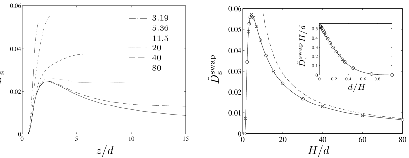
Our numerical results for the swapping contribution (16) to the effective self-diffusion coefficient are presented in figure 14. The left panel shows versus for several values of channel widths, and the right panel shows the self-diffusivity at the channel center as a function of . The results of our calculations indicate that for the self-diffusion coefficient achieves its maximal value at the channel center, where the swapping effect is the strongest due to the superposition of the flow reflected from two walls. In contrast, for the maximum occurs at the distance from each wall. The results also show that particle migration is suppressed near the walls, which is consistent with the observation that the vertical extent of the particle-swapping domain is small near the walls (cf. the bottom panels of figure 10). The effect of the decreased self-diffusivity in the near-wall regions is reflected in the shapes of the density profiles depicted in figure 13.
The behavior of for can be determined by combining relations (10) and (16) and recalling that the lateral extent of the swapping region scales with for the large channel width (as depicted in the top panel of figure 10). Accordingly, we obtain the relation
| (17) |
where depends on the position of the particle pair across the channel . For particles in the midplane we find , according to the results shown in the inset of the right panel of figure 14.
4.3 Comparison with experiment by Zarraga and Leighton
While the mechanism for particle migration due to the swapping trajectories has not been proposed so far, the effect of the swapping motions was observed when Zarraga & Leighton (2002) reported unusually large values of the hydrodynamic self-diffusivity for a dilute suspension of spheres undergoing shear flow in a Couette device. Their measurements gave the result (where is the particle radius) for the low-density self-diffusion coefficient, whereas the estimate of the contribution due to particle roughness was at least four times smaller: it ranged from to , depending on the assumed roughness amplitude. This discrepancy has been unaccounted for, and the result of Zarraga & Leighton (2002) experiment has been puzzling.
By analyzing the effect of the channel walls on particle motion we provide a simple explanation for the anomalous value of the self-diffusion coefficient. The Zarraga & Leighton (2002) measurements were performed in a channel with wall separation . For this geometry we find that the swapping contribution to the self-diffusion coefficient in the center of a channel is . Moreover, in the whole central region the diffusivity only weakly depends on the position , according to the results shown in figure 14. Assuming the upper limit of the roughness parameter quoted by Zarraga & Leighton (2002), we find (note that is slightly smaller than the corresponding value in infinite space because the swapping mechanism reduces the rate of direct particle collisions). Combining the swapping and roughness contributions, we obtain for the total self-diffusion coefficient. Our result agrees with the experimental value with accuracy of 15 %.
In this paper we focus on systems of equal-size spheres but wall-induced cross-streamline particle migration also occurs in bidisperse or polydisperse suspensions. We note that in such suspensions, migration resulting from particle roughness is significantly smaller than in monodisperse ones (Zarraga & Leighton, 2001, 2002). Thus in polydisperse systems particle swapping constitutes the dominant particle migration mechanism even if there is significant particle roughness.
Moreover, cross-streamline displacements of two different-size particles undergoing a binary swapping encounter differ because there is no fore–aft symmetry. It follows that the total suspension density is affected by the swapping trajectories, in addition to the migration of individual particle species. In contrast, in monodisperse suspensions the total density cannot be altered by position-swapping binary encounters.
5 Conclusions
The key finding of our study is that confining walls can qualitatively change the topology of binary encounters of spherical particles in suspension flows. Specifically, we have identified a new class of binary trajectories that result in cross-streamline particle migration in a wall-bounded shear flow. Equal-size spheres on such trajectories do not pass each other (as in an unbounded system) but, instead, they exchange their transverse positions. While our explicit calculations are limited to equal-size spherical particles in shear flow bounded by parallel planar walls, we expect that a similar effect also exists for pressure-driven flows, particles of different sizes, and other wall geometries.
We have shown that the cross-streamline particle motion is driven by the wall reflection of the scattered flow produced by the particles. Namely, the reflection of the flow produced by one of the spheres pushes the other approaching sphere across the streamlines of the external flow towards the fluid region moving in the opposite direction. Due to this mutual interaction, the particles turn around and return to infinity without passing each other – they exchange their vertical positions instead.
The significance of our results stems from the fact that the wall-induced transverse particle displacements associated with position-swapping binary encounters constitute the sole mechanism for cross-streamline migration of spherical non-Brownian particles at low suspension concentrations (if there are no non-hydrodynamic forces). Such migration was indeed observed by Zarraga & Leighton (2002) who found anomalously large self-diffusion coefficient in a confined suspension of spheres. Up till now, however, their measurements have remained unexplained. In this paper we show that the swapping mechanism quantitatively explains the unexpected results of their experiments.
A sequence of uncorrelated binary position-swapping particle encounters in a monodisperse suspension causes a macroscopic self-diffusion process. In multi-component systems a sequence of such encounters results in mutual diffusivity. Moreover, the swapping trajectories produce migration not only in the velocity-gradient direction (considered herein) but also in the direction of fluid vorticity.
In addition to our two-particle results, we have found that in the wall presence there is a domain of recirculating streamlines around a single sphere in shear flow. Such recirculating streamlines result in fluid mixing in suspension flows, so this phenomenon may have important microfluidic applications. Furthermore, the trajectory reversal associated with particle swapping behavior may prevent near-contact particle encounters by causing the particles to separate before arriving into a near-contact configuration. Such a hydrodynamic shielding effect may be especially important for a chain of particles with slightly different cross-streamline positions in a microfluidic channel. Thus, proper understanding of the position-swapping mechanism may contribute towards finding better methods of controlling particle motions in microfluidic devices.
Other consequences of the particle-swapping mechanism will be described in our forthcoming publications. In particular, we will show that binary particle collisions in a dilute suspension under shear may produce a layered particle distribution. Our preliminary results concerning such a layering process have already been presented (Zurita-Gotor, Bławzdziewicz & Wajnryb, 2005).
We would like to thank our reviewers for calling our attention to the experimental results by Zarraga & Leighton (2001), and for providing some alternative explanations of the swapping mechanism. We would also like to acknowledge helpful suggestions by David Leighton regarding explanation of the swapping mechanism in terms of the wall reflection of the stresslet, using equation (16) to evaluate the self-diffusion coefficient, and showing the asymptotic relation (17). This work was supported by NSF grant CTS-0348175 (MZG and EW), NASA grant NAG3-2704 (MZG), Junta de Andalucia grant EXC/2005/TEP-985, and by Polish Ministry of Science and Higher Education grant N501 020 32/1994 (EW).
Appendix A Flow reflected from rigid wall
According to the Lorentz (1907) expression, the wall reflection of the flow field (6) in a rigid wall at can be expressed by the following formulas (Bhattacharya & Bławzdziewicz, 2002),
| (18) |
where
| (19) |
| (20) |
| (21) |
In the above relations, is the coordinate relative to the source position, is the identity tensor, , and is the reflection operator with respect to the plane ,
| (22) |
By inserting (6) into (18) and evaluating the order of magnitude of different terms, we find that the overall decay of the reflected flow with the wall-particle distance is . Equations (6) and (18) also indicate that the vertical component is an odd function of the variable . Therefore, for we find
| (23) |
Appendix B Location of zeros of in the plane
The critical interparticle distance does not depend on the orientation of the particle pair in the plane , which can be shown by decomposing the external flow (2) into the longitudinal component (along the line connecting particle centers) and transverse component (normal to this line),
| (24) |
By symmetry, the transverse velocity does not produce any vertical particle motion. Therefore, only the longitudinal problem defines the location of zeroes of . Moreover, the location of points does not vary with the magnitude of the projection . Thus the distance is independent of the orientation of the vector .
By a similar argument one can demonstrate that the upstream swapping-trajectory domain in the variables () is delimited by a straight line section for (as shown in the top panel of figure 10). The straight-line section corresponds to trajectories that pass through the circle of zeros of . Since the transverse component of the external flow does not produce any vertical particle motion, for all initial orientations of the particle pair on the circle the vertical evolution of the particles is thus the same, except for a varying time scale.
Using the flow decomposition (24) one can also show that for a given , the vertical velocity varies as with the polar angle of the relative-position vector ( varies with in the same way as the flow component . The plots of vs shown in figure 4 are thus sufficient to determine for all orientations of a particle pair in a given plane .
We would also like to mention that our numerical results indicate that additional changes of sign in the relative vertical velocity may occur at large interparticle distances. This would lead to more complex particle recirculation patterns than those described herein. However, the magnitude of at large distances is extremely small due to the exponential decay of the vertical velocity (Bhattacharya et al., 2006a). Therefore, domains of trajectories with different topology are limited to very small regions in the configurational space. We note that multiple changes in sign of the velocity field in a parallel-wall channel were described by Hackborn (1990) for a flow produced by a vertical rotlet.
Appendix C Proof of relation (10)
As we have shown in our previous publications (Bhattacharya et al., 2006a, b), the vertical velocity components for two spheres in Stokes flow in a parallel-wall channel decay exponentially on the lengthscale . Thus, the vertical offset of the particles along the pair trajectory evolves only for . The relative lateral velocity of the particles in shear flow (2) is , where is a typical vertical offset along the trajectory. Therefore,
| (25) |
is the timescale for the evolution of the vertical particle positions. During the time interval (25) the vertical offset may attain the magnitude
| (26) |
where is the typical value of the vertical component of the relative particle velocity.
According to equation (6), the perturbation velocity field produced by a spherical particle of diameter in an unbounded shear flow with the shear rate scales as , where is the distance from the particle. In a wall-bounded system, this perturbation flow interacts with the walls at the distance and then acts on the second particle at a distance , producing its vertical motion. Therefore, the relative vertical velocity of the particles has the magnitude
| (27) |
References
- Acrivos et al. (1992) Acrivos, A., Batchelor, G. K., Hinch, E. J., Koch, D. L. & Mauri, R. 1992 Longitudinal shear-induced diffusion of spheres in a dilute suspension. J. Fluid Mech. 240, 651–657.
- Arp & Mason (1977) Arp, P. A. & Mason, S. G. 1977 Kinetics of flowing dispersions. VIII. Doublets of rigid spheres (theoretical). J. Colloid Interface Sci. 61, 21–43.
- Batchelor & Green (1972) Batchelor, G. K. & Green, J. T. 1972 The hydrodynamic interaction of two small freely-moving spheres in a linear flow field. J. Fluid Mech. 56, 375–400.
- Bhattacharya & Bławzdziewicz (2002) Bhattacharya, S. & Bławzdziewicz, J. 2002 Image system for Stokes-flow singularity between two parallel planar walls. J. Math. Phys. 43, 5720–31.
- Bhattacharya et al. (2005a) Bhattacharya, S., Bławzdziewicz, J. & Wajnryb, E. 2005a Hydrodynamic interactions of spherical particles in suspensions confined between two planar walls. J. Fluid Mech. 541, 263–292.
- Bhattacharya et al. (2005b) Bhattacharya, S., Bławzdziewicz, J. & Wajnryb, E. 2005b Many-particle hydrodynamic interactions in parallel-wall geometry: Cartesian-representation method. Physica A 356, 294–340.
- Bhattacharya et al. (2006a) Bhattacharya, S., Bławzdziewicz, J. & Wajnryb, E. 2006a Far-field approximation for hydrodynamic interactions in parallel-wall geometry. J. Comput. Phys. 212, 718–738.
- Bhattacharya et al. (2006b) Bhattacharya, S., Bławzdziewicz, J. & Wajnryb, E. 2006b Hydrodynamic interactions of spherical particles in Poiseuille flow between two parallel walls. Phys. Fluids 18, 053301.
- Bossis & Brady (1987) Bossis, G. & Brady, J. F. 1987 Self-diffusion of Brownian particles in concentrated suspensions under shear. J. Chem. Phys. 87, 5437–5448.
- Cichocki et al. (2000) Cichocki, B., Jones, R. B., Kutteh, R. & Wajnryb, E. 2000 Friction and mobility for colloidal spheres in Stokes flow near a boundary: The multipole method and applications. J. Chem. Phys. 112, 2548–61.
- da Cunha & Hinch (1996) da Cunha, F. R. & Hinch, E. J. 1996 Shear-induced dispersion in a dilute suspension of rough spheres. J. Fluid Mech. 309, 211–223.
- Drazer et al. (2002) Drazer, G., Koplik, J., Khusid, B. & Acrivos, A. 2002 Deterministic and stochastic behavior of non-Brownian spheres in sheared suspensions. J. Fluid Mech. 460, 307–335.
- Eckstein et al. (1977) Eckstein, E., Bailey, D. & Shapiro, A. 1977 Self-diffusion of particles in shear flow of a suspension. J. Fluid Mech. 79, 191–208.
- Hackborn (1990) Hackborn, W. W. 1990 Asymmetric Stokes flow between parallel planes due to a rotlet. J. Fluid Mech. 218, 531–46.
- Kim & Karrila (1991) Kim, S. & Karrila, S. J. 1991 Microhydrodynamics: Principles and Selected Applications. London: Butterworth-Heinemann.
- Kulkarni-Morris (2007) Kulkarni-Morris 2007 Pair-sphere trajectories in finite Reynolds number shear flow. J. Fluid Mech. p. submitted.
- Leighton & Acrivos (1987) Leighton, D. & Acrivos, A. 1987 The shear-induced migration of particles in concentrated suspensions. J. Fluid. Mech. 181, 415.
- Lin et al. (1970) Lin, C., Lee, K. & Sather, N. 1970 Slow motion of 2 spheres in a shear field. J. Fluid Mech. 43, 35–47.
- Lorentz (1907) Lorentz, H. A. 1907 A general theory concerning the motion of a viscous fluid. Abhandl. Theor. Phys. 1, 23.
- Mikulencak & Morris (2004) Mikulencak, D. R. & Morris, J. F. 2004 Stationary shear flow around fixed and free bodies at finite Reynolds number. J. Fluid Mech. 520, 215–242.
- Press et al. (1992) Press, W. H., Vetterling, W. T., Flannery, B. P. & Teukolsky, S. A. 1992 Numerical Recipes in Fortran 77: The Art of Scientific Computing. Cambridge: Cambridge University Press.
- Subramanian & L. (2006) Subramanian, G. & L., K. D. 2006 Inertial effects on the transfer of heat or mass from neutrally buoyant spheres in a steady linear. Phys. Fluids 18, Art. No. 073302.
- Wang et al. (1996) Wang, Y., Mauri, R. & Acrivos, A. 1996 The transverse shear-induced liquid and particle tracer diusivities of a dilute suspension of spheres undergoing a simple shear flow. J. Fluid Mech. 327, 255–272.
- Wang et al. (1998) Wang, Y., Mauri, R. & Acrivos, A. 1998 shear-induced gradient diusion in a dilute suspension of spheres. J. Fluid Mech. 357, 279–287.
- Zarraga & Leighton (2001) Zarraga, I. E. & Leighton, D. T. 2001 Shear-induced diffusivity in a dilute bidisperse suspension of hard spheres. J. Colloid Interface Sci. 243, 13.
- Zarraga & Leighton (2002) Zarraga, I. E. & Leighton, D. T. 2002 Measurement of an unexpectedly large shear-induced self-diffusivity in a dilute suspension of spheres. Phys. Fluids 14, 2194–2201.
- Zinchenko (1984) Zinchenko, A. 1984 Effect of hydrodynamic interactions between the particles on the rheological properties of dilute emulsions. Prikl.Matem.Mekhan. 48, 198.
- Zurita-Gotor et al. (2005) Zurita-Gotor, M., Bławzdziewicz, J. & Wajnryb, E. 2005 Boltzmann Monte-Carlo simulations of a suspension of non-spherical particles in a parallel-wall channel. Bull. Am. Phys. Soc. 50, 229.
- Zurita-Gotor et al. (2007) Zurita-Gotor, M., Bławzdziewicz, J. & Wajnryb, E. 2007 Motion of a rod-like particle between parallel walls with application to suspension rheology. J. Rheol. 51, 71–97.