Dispersive effects on optical information storage in Bose-Einstein condensates using ultra-slow short pulses
Abstract
We investigate potential of atomic Bose-Einstein condensates as dynamic memory devices for coherent optical information processing. Specifically, the number of ultra-slow pulses that can be simultaneously present within the storage time in the condensate has been analyzed. By modelling short pulse propagation through the condensate, taking into account high-order dispersive properties, constraints on the information storage capacity have been discussed. The roles of temperature, spatial inhomogeneity, the interatomic interactions and the coupling laser on the pulse shape have been pointed out. For a restricted set of parameters, it has been found that coherent optical information storage capacity would be optimized.
I Introduction
The remarkable achievement of ultraslow lightslowlight-exp1 ; slowlight-exp2 ; slowlight-exp3 in a Bose-Einstein condensate (BEC), using electromagnetically induced transparencyeit1 ; eit2 ; eit3 (EIT), inspired many intriguing and attractive applicationsslowlight-apps1 ; slowlight-apps2 ; slowlight-apps3 ; slowlight-apps4 , in particular quantum optical dynamic memoriesqmemory1 ; qmemory2 ; qmemory3 ; qmemory4 ; qmemory5 . A key component of a quantum information processor would be the dynamic memory storage device. BECs have the potential to be used in such an application. Consider a sequence of information bits carried by a train of optical pulses. Upon injection into a BEC, the coherent optical information can be stored for a period given by the transit time of the pulses. In the BEC phase, the demonstrated ultra-slow group velocities allow for long storage periods of the order of few microseconds. Operational performance of such a device can be characterized by the overall bit storage capacity of the BEC, which can be defined as the number of optical pulses that can be simultaneously stored during the storage time in the BEC.
In order to make quantum memories more practical for quantum information processing, it is useful to enhance their bit storage capacity. This would be possible, in principle, by using pulses temporally as short as possible so that more pulses can be injected into the BEC during the storage timeliu . Early ultraslow light experiments use pulses of widths few microseconds. Shorter pulses would have longer frequency bandwidths, beyond the EIT window. EIT window can be modified by an external magnetic fieldwei . Very recently, it has been experimentally demonstrated that EIT in a resonant atomic medium is possible for a comb of picosecond pulsesshortpulse-exp . Promising schemes to introduce large controllable time delays for such ultrashort pulses has been proposed where EIT window is overcome by using spatial and temporal processingshortpulse-prop . Distortions in the shape of a large-bandwidth pulse have been experimentally studied in warm Rb vaporbashkansky . Shapes of the stored pulses will depend on the dispersive characteristics of the BEC. In particular, each pulse in the train will undergo dispersive broadening. The temporal separation of the pulses should be adjusted in such a way that after broadening in the BEC, consecutive pulses do not have significant spatial overlap. This sets the limit to the bit storage capacity of the BEC and can be estimated from the overall group delay and pulse broadening. It is therefore necessary to investigate the dispersive effects inside a BEC and develop accurate models that describe pulse propagation.
In this paper, we consider propagation of short pulses with widths in the microseconds to nanoseconds range. In particular, we investigate the role of dispersion on the temporal characteristics of optical pulses propagating inside a BEC. Analytical formulas are first summarized for the constitutive relations from which the group delay, absorption coefficient, and the second-order group delay dispersion can be calculated. We find that third and higher-order dispersion effects are negligible. The influence of the spatial inhomogeneity of the BEC, the interatomic scattering interactions and the temperature on the pulse shape are taken into account in our treatment. We show that just below the critical temperature of condensation, broadening becomes maximum. Finally, we give analytical formulas for the bit storage capacity of a BEC and determine its optimum performance.
II Propagation and dispersion of slow-light pulses in an atomic ensemble under EIT scheme
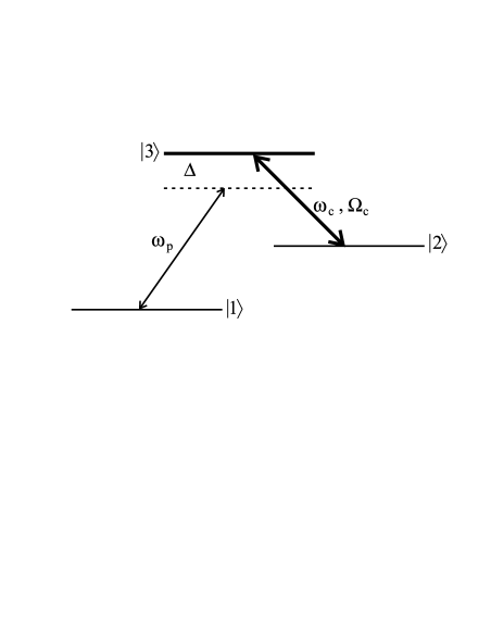
We consider a gas of three-level atoms interacting with two laser beams in configuration as shown in Fig.1. In this scheme, it is assumed that the only dipole forbidden transition is the one between the lower levels. The upper level is coupled to the lower levels via a strong drive field with frequency and a weak probe field of frequency . This particular arrangement leads to the well-known effect of electromagnetically induced transparency (EIT) in which the absorption of the probe field at resonance is cancelled. The underlying physical mechanism of EIT is the quantum interference induced by the drive field. Quantum coherence established between the lower level doublet put them in a dark state where excitations to the upper level become impossible. The transition probabilities destructively interfere for the two possible excitation routes to the upper level. In addition to turning an optically thick, opaque, medium transparent, EIT has recently been used for achieving ultra-slow light velocities, owing to the steep dispersion of the EIT susceptibility near the probe resonance. Susceptibility for the probe transition can be calculated as a linear response as most of the atoms remain in the lowest state. Assuming local density approximation, neglecting local field, multiple scattering and quantum corrections and employing steady state analysis, is found to beeit3
| (1) |
where is the frequency detuning of the probe field with frequency from the resonant electronic transition . For the cold gases considered in this paper and assuming co-propagating laser beams, Doppler shift in the detuning is neglected. It is assumed that the drive field is at resonance. is the Rabi frequency of the drive field; is the dipole matrix element between states and which can also be expressed in terms of resonant wavelength of the probe transition via with is the radiation decay rate between and . and denote the dephasing rates of the atomic coherences between the appropriate states. stands for a given atomic density.
Probe beam propagates along the condensate axis in the direction. We treat the axial propagation of probe beam under paraxial approximation where the paraxial effects and diffraction losses are ignored. This approximation is valid when the probe beam radius is much larger than the radial size of the atomic cloud. In practice, using a pinhole and a flipper mirror, only that portion of the probe beam passing through the thin central column region of the cloud is selectively monitoredslowlight-exp1 . To develop a one dimensional wave equation including the high order diffraction effects in the dispersive medium for the short probe pulse, we follow Ref.Harris .
The probe pulses we shall consider in this paper have carrier frequencies in the order of Hz, while their spectral widths are less than of the order of Hz. We will study their propagation under slowly varying phase and envelope approximations. The wave equation that would govern the propagation of a short pulse in a dispersive medium can be found to beHarris
| (2) |
where determines the pulse attenuation; is the group velocity, and is the second-order dispersion coefficient, or the group velocity dispersion. We have also calculated the third order dispersive coefficient and found it to be orders of magnitude less than for typical experimental parametersslowlight-exp1 . The significant coefficients for the short pulse propagation can be calculated from the susceptibility using the relationsHarris
| (3) | |||||
| (4) | |||||
| (5) |
Here we take , and for convenient notation. It may be noted that these expressions lead to complex parameters in general, as the is a complex valued function and the parameters are merely mathematical coefficients in Eq.2. At EIT resonance however they lead to physically meaningful, well-defined, real valued absorption coefficient, group velocity and dispersion coefficient. EIT susceptibility exhibits steep normal dispersive behavior around the resonance, which allows for the second term in Eq.4 become much larger than the first term. This leads to substantial reduction in the group velocity of the pulse. Such a slow pulse propagates through the medium without much absorption due to the small imaginary EIT susceptibility at resonance. On the other hand, for short pulses the pulse shape would also be influenced by the higher order dispersive coefficients, starting from the group velocity dispersion. Different frequency components would have different velocities and broadening of the pulse may become significant. Let us emphasize that essential physical foundations of these effects are not related to the density but the dispersive properties of the EIT susceptibility. Indeed, slow laser pulses have been observed in various media, including hot rubidium vaporslowlight-hotgas1 ; slowlight-hotgas2 , ultracold Bose gasslowlight-exp1 , and in solid crystalsslowlight-solid . When Rabi frequency for the coupling field is sufficiently large such that , we can calculate these parameters characterizing propagation and dispersion of slow EIT pulses explicitly as follows
| (6) | |||||
| (7) | |||||
| (8) |
It should be noted that the result for is valid when
| (9) |
For m-3, the upper limit would be . In this paper we consider . Corresponding electric field of the coupling laser then would be in the range V/m, with power densities W/m2. is used in typical experimentsslowlight-exp1 . We shall discuss possible enhancement of bit storage capacity by selecting particular within this range. According to their dependencies on the , we see that increasing reduces the dispersive effects significantly, but simultaneously it reduces the storage time of the pulses in the condensate as the group velocity would rise. It is illuminating to realize that decrease of delay time (storage time) is much slower than the decrease of dispersion coefficient with the . This can be exploited to find a critical for which number of probe pulses injected into the medium within the storage time would be optimized.
We note that for extremely large , one should use the following expression instead
| (10) |
For a uniform density medium the Eq.2 can be solved analyticallybahaa . An initial temporally short gaussian pulse after propagating in the medium of length is then found to be delayed with respect to a reference pulse propagating in vacuum by . During that time, the pulse would broaden due to second-order dispersion. Leaving the medium, it would grow to a final width of
| (11) |
with is the initial temporal width of the pulse, and . For we get .
In general, is a spatially varying function, whose profile depends on temperature, inter-atomic interactions and confinement potential. Assuming slow spatial variations within an optical wavelength the wave equation remains the same. The only effect of spatial inhomogeneity would be to give group velocity and its dispersion local character. As a result, the time delay can be calculated through a spatial averaging of the group velocity fieldmorigi . Experimentally measured group velocity is then operationally defined by , where the effective axial length of the medium is evaluated by
| (12) |
The axial length is an effective length corresponding to the axial width of the density distribution. It may be noted that more exact treatments can be used to determine the effective length of an interacting BEC as discussed in detail very recentlylength . There is no simple operational definition for the broadening of the pulse. One has to either determine the output pulse shape from exact numerical simulations of the wave equation or refer to uniform density results for qualitative studies. While it is the atomic density which determines the local group velocity and its dispersion, after spatial averaging, the group velocity and broadening of the pulse would become explicitly dependent on the temperature, interactions between the atoms as well as the other physical parameters due to the confinement potential. In order to elucidate these dependencies, it is necessary to define concretely and discuss how it is shaped by such physical parameters. We shall specifically consider an atomic Bose-Einstein condensate as the medium of propagation in this paper and review its density profile in the next section.
III Density profile of a trapped semi-ideal Bose gas at finite temperature
At low temperatures a Bose gas can be considered to be composed of two components. The first component becomes the condensate part and the other is a thermal gas background. In a harmonic trap, spatial overlap between the components becomes small, which makes effects of collective elementary excitations weaker relative to those in homogeneous gases. This allows for semiclassical descriptions of density distributions in terms of the self-consistent Hartree-Fock model, which simplifies more general Hartree-Fock-Popov descriptiongiorgini . When the thermal component is dilute enough, one may further neglect the atomic interactions in the thermal component. Taking into account mean field repulsion only among the condensed atoms, an analytical explicit description of a partly condensed gas was developed and denoted as the semi-ideal modelnaraschewski . We will now briefly review this model, where condensate density is evaluated under Thomas-Fermi approximationtfa1 ; tfa2 to Gross-Pitaevskii equationgpe1 ; gpe2 , and the thermal gas density is calculated semi-classicallyBagnato ; naraschewski . The total density at a temperature is then written to be
| (13) |
where ; is atomic mass; is the atomic s-wave scattering length; is the chemical potential; is the Heaviside step function; is the Bose function; is the thermal de Bröglie wavelength; ; is the fugacity, and is the critical temperature. The external trapping potential is with the radial trap frequency and the angular frequency in the z direction. is determined from . At temperatures below this yieldsnaraschewski
| (14) |
where is the chemical potential evaluated under Thomas-Fermi approximation and the condensate fraction is given by
| (15) |
with , and is the Riemann-Zeta function. The scaling parameter , characterizing the strength of atomic interactions within the condensate, is calculated to benaraschewski ; giorgini
| (16) |
Here, denotes the average harmonic oscillator length scale. At temperatures above the , can be determined from , where is the third-order polylogarithm function. The semi-ideal model has a wide-range of validity in representing density distribution of a trapped Bose gas at finite temperature provided that naraschewski . At the same time the interactions are assumed to be strong enough to ensure so that kinetic energy of the condensate can be neglected according to the Thomas-Fermi approximation. In typical slow-light experiments in cold atomic gases, remains within these limits. We shall use the semi-ideal model given density profile in our investigations of propagation and dispersion of slow pulses and present our explicit results in the next section.
IV Results and discussions
In our numerical calculations of the theoretical results presented in the preceding section, we shall specifically consider a gas of 23Na atoms for which amu, nm, MHz, , Hz, and nm. For the parameters of the trapping potential, we take Hz and Hz as in Ref.slowlight-exp1 . The coupling field Rabi frequency is taken to be slowlight-exp1 . Critical temperature for Bose-Einstein condensation of such a gas is found to be nK. We illustrate the spatial density profile of the condensate in the axial () direction at nK in Fig.2.
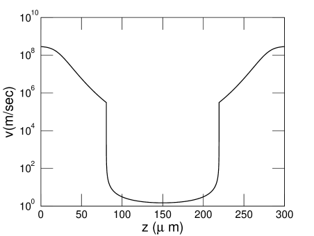
Due to spatially inhomogeneous density, the linear dielectric susceptibility would also be spatially inhomogeneous. In this case, group velocity defined by Eq.(7) would have a local character. Under EIT conditions, when the light pulse enters the condensate from the thermal component of the gas, its group speed exhibits a dramatic slowing down as shown in Fig.3. Here we consider resonant probe pulse with . Within the condensate region, at such low temperatures, the group velocity remains roughly at the same ultraslow value. The pulse rapidly accelerates to high speeds when it leaves the condensate at the interface to thermal component. Before and after the thermal component, the pulse is assumed to be propagating in vacuum. In practice, group velocity is measured in terms of time delay of the pulse with respect to a reference pulse propagating in vacuum over the same distance with the gas. To make comparisons with this operational definition of the group velocity, one needs to make careful spatial averaging of the theoretical group velocitymorigi .
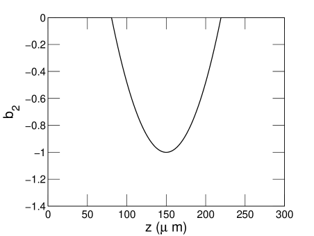
The other coefficients in the wave equation are also locally defined. The coefficient of absorption and the second-order dispersion coefficient are shown in Fig.4 and in Fig.5, respectively. Under EIT conditions, imaginary part of is small, despite the large condensate density. For large we have . For short pulse propagation we shall see that the major source of reduction in the peak of the pulse would be the temporal broadening due to dispersion. The absorption over the small size of the BEC is negligibly small. Taking m-1 and m, we can roughly estimate attenuation of the pulse by , which yields about transmission. The loss term can be made smaller by using larger Rabi frequencies for the coupling control field. The positive sign of reflects its effect on the pulse as the decrease of the pulse intensity. The broadening of the pulse on the other hand is independent of the sign of , as can be deduced from Eq.11.
The region over which dispersive effects are most strong is a small region near the center of the cloud as can be seen in Fig.5. The size of this region can be determined by the width of the density distribution, since is proportional to . It is quite smaller than the classical boundary . As an example, m in Fig.2, while the condensate is extended over a size of m. In such a small region, spatial variations of can be ignored so that . When a pulse of width enters into this strongly dispersive zone, its final width would approximately broaden to , where . Broadening of the pulse depends on the density profile of the medium through its characteristic parameters, its peak value , and its width . For small dispersion, change in the pulse width would be proportional to . For the given within the semi-ideal model, demonstrates the well-known temperature variationgiorgini as shown in Fig.6. At a given temperature, has been evaluated by Eq.12. At very high temperatures, , classical thermal radius would be according to the equipartition theorem. In the temperature range of Fig.6, beyond , is changing linearly with . It might be illuminating to rewrite Eq.12 as . Here, stands for a mean square axial distance evaluated using either condensate (C) or thermal density (T) distribution. The sharp drop of the width of the distribution just below is due to the emergence of condensed component with relatively high density about the center of the cloud. As becomes lower, thermal component shrinks, while the condensate part expands slowly about the center of the cloud. eventually saturates down to Thomas-Fermi width at zero temperature. The thermal behavior of the peak density is also well-knownnaraschewski ; giorgini . At high temperatures it shows decay consistent with classical gas behavior. Just below , grows rapidly due to emerging relatively dense condensate about the center of the cloud. At extremely low temperatures, saturates to Thomas-Fermi density.
Fig.7 describes dependence of broadening on temperature and interatomic interaction. At extremely low temperatures, and are determined by the condensate part and they change slowly with . For increasing , thermal part expands beyond the boundaries of the condensate, so that will be contributed significantly by the thermal part. Except at temperatures close to , is dominated by the condensate part, which exhibits slow dependence on in comparison to that of . As a result, the product grows, following the expansion of thermal component, up to a point just below , where dramatically drops to dilute thermal density value due to rapid disappearance of the dense condensate component. After that peak point, shows faster variation with relative to that of . Hence, the shape of broadening curve is characterized by the thermal behavior of . At temperatures higher than , broadening decreases with temperature. At such high temperatures, grows slowly (almost linear) while decreases like . Thus their product becomes a decreasing function with . Summarizing, the broadening is determined by the density profile through its characteristic product . As and exhibit competing thermal behaviors, a peak arises just before the , a signature of emerging condensate being a strongly dispersive region. Before the peak point, it is which shapes the temperature dependence of the broadening. After the peak point, broadening behaves analogous to the thermal behavior of .
Earlier studies indicate that group velocity depends on the strength of atomic interactions within the condensate which is characterized by the s-wave scattering length . As the grow longer, the group velocity of the pulse within the BEC becomes fasterMustecaplioglu . In order to discuss the influence of atomic interactions on broadening of the pulse, we first note that below the atomic energies are so low that, there is only , s-wave scattering length, to characterize the strength of interactions within the condensate component. At higher temperatures beyond , the interactions has no effect within the semi-ideal model where thermal gas is dilute and non-interacting. In Fig.7, we see that as the increases, the broadening decreases when . According to semi-ideal model density profile, we get at , from which we conclude . This is intuitively expected, as the increase of repulsive atomic interactions results in lower densities. The width of the atomic cloud would slightly increase with . The increase of the size of the condensate can be estimated from the Thomas-Fermi axial radius given by . Thus, we see that the increase of would be slower than the decrease of the , so that and hence the broadening would reduce with . This conclusion remains the same at higher temperatures where the thermal length scale becomes dominant in determining , and it is not influenced by . Thus, broadening decreases due to decrease of . Beyond , the density profile is semi-classically determined and is independent of . The semi-ideal model density profile becomes not as good description of the condensate when the interactions characterized by the scaling parameter becomes larger than , corresponding to nm. For 23Na cloud, nm. The higher may be achieved by utilizing Feshbach resonance techniquefedichev ; bohn ; inouye or by considering alternative atoms.
Our approach in determining the pulse broadening using the effective medium width , as we will show below, gives qualitatively accurate behavior of the broadening but overestimates it. In an actual pulse propagation, a pulse of width would be prepared far from the gaseous medium. Before reaching to the most dispersive zone about the center of the cloud, the pulse would pass through the thermal cloud and then through the edges of the condensate. Due to the inhomogeneous density profile, when the pulse arrives to the center of the cloud, it would already be much broader than . As a result it would suffer less from dispersion than the one predicted above. Despite the lack of actual input value for our analysis above, the overall qualitative behavior is expected to be accurate. To test this expectation and to justify our effective central dispersive zone treatment agree qualitatively with the exact pulse behavior, we now investigate the variation of the pulse width with distance of propagation, taking into account the full spatially inhomogeneous density profile of the gaseous medium. We assume a Gaussian pulse of the form at initial time , , where is the pulse width, and propagate it numerically. A dimensionless form of Eq.(2) is solved via finite difference Crank-Nicholson space marching scheme. The Crank-Nicholson scheme is less stable but more accurate than the fully implicit method; it takes the average between the implicit and the explicit schemesGarcia . We use forward difference scheme for the position and central difference scheme for the time. Discrete equations in matrix form are solved using Thomas algorithmGarcia which is analogous to a fast Gaussian elimination method for tridiagonal matrices.
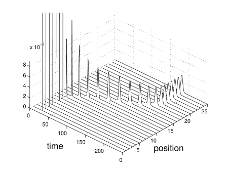
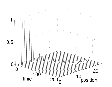
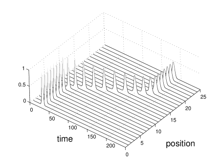
We have performed extensive numerical simulations at various and confirmed that despite being an overestimation, the qualitative behavior predicted in Fig.7 correctly describes the results obtained by the exact solution. We present typical results of our simulations in Figs.8-11. For a nanosecond pulse, at nK, broadening is s which can be seen in Fig.9. This is much smaller than the result found by the uniform density calculation, which gives s at the same temperature in Fig.7. More moderate broadening is obtained for a pulse of width s and shown in Fig.10. As a rule of thumb, we assume that broadening is not significantly large if it is less than a factor of . A microsecond pulse broadens by a factor of as can be seen in Fig.11. For longer pulses therefore we conclude that broadening is not significant.
In early ultraslow light experiments microsecond pulses were usedslowlight-exp1 . Previous theoretical models ignore dispersion effects in the pulse propagation. While they can be used to describe observed group velocities, they cannot explain the transmitted pulse shape adequately. High-order dispersion, absorption, transverse diffraction, and off-resonant transitions to upper levels not included in the three-level model cause imperfect transition, and result in reduction of the transmitted peak intensity. We have already argued that absorption, though still present even under EIT conditions, makes a little effect over the small BEC size. Transverse diffraction due to paraxial pulse propagation is also not too strongMustecaplioglu . To characterize the contribution of second-order dispersion on the reduction of the peak intensity, propagation of a microsecond pulse is simulated and presented in Fig.11. This result indicates that in addition to off-resonant transitions to other levels, broadening of the pulse also contributes to the observed drop of the transmitted peak intensity.
While microsecond pulses are good to minimize dispersive effects, shorter pulses may be more attractive for optical information processing. The question we would like to now address is if such shorter pulses can still be stored as efficiently via EIT scheme in atomic ultracold gases. We may characterize coherent optical information storage capacity through a parameter given by . It measures number of probe pulses simultaneously present in BEC without significant overlap. The storage time is taken to be the delay time of the pulses, . We choose an ideal repetition rate of the pulse train to be . The pulses are assumed to be stored in the central region of the cloud, whose length is given by Eq.12. It is the same with the effective central dispersive zone considered in the analytical broadening calculation. In this region is approximately uniform at its peak value, leading to spatially homogeneous , that can be seen in Fig.3. More explicitly, becomes
| (17) |
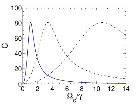
The second term under the square root in the denominator represents the second-order dispersive contribution. When dispersion is not too strong, could be made higher by increasing . On the other hand, it is not very simple task to increase for BEC. Besides, it implicitly and indirectly affects the dispersive term via . For a given , more explicit and direct control parameter would be . exhibits a non-trivial dependence on , which is illustrated in Fig.12. We observe that for given atomic cloud, and , there is an optimum choice of . Fig.12 also compares for different . We deduce that, for a wide range of it is indeed possible to inject more pulses by using shorter . However, reducing from s to s, one cannot hope to increase the capacity times more. Instead, due to dispersive effects, only by using a critical coupling laser Rabi frequency, storage capacity can be made maximum. The maximum achievable capacity is independent of , and is found to be
| (18) |
which is evaluated at the critical coupling Rabi frequency, , given by
| (19) |
These results suggest that shorter pulses can be stored in the cloud as efficiently as microsecond pulses. The storage time when becomes
| (20) |
We note that analytical result of underestimates the actual value of it, as is overestimated. Due to spatial inhomogeneity, , pulse width just before the central zone, would be larger than the width of the original pulse prepared away from the atomic cloud, so that would be smaller. would remain the same under any pulse width change. As a result, actual would be higher than the one predicted above. The analytical expressions are mainly good for predicting qualitative behavior of with , and providing a lower limit for its value.
V Conclusion
We have examined dispersive effects on short pulse propagation through a semi-ideal BEC under EIT scheme. We have found that third and higher order dispersion coefficients are negligibly small for current experimental systems. Distortion of the shape of a short pulse in the atomic cloud would be a temporal broadening arising from second-order dispersion per se. For pulses of widths greater than microseconds we have found that second order dispersion is also negligible. For microsecond pulses the broadening is about of the initial width. As a rule of thumb, when the pulse length is broadened by less than a factor of , the pulse can be considered to be not significantly distorted.
Second order dispersion of the atomic cloud depends on its density profile, which is determined mainly by temperature and atomic interactions. For nanosecond pulses, we have presented the dependence of the broadening on the temperature and interatomic scattering. The broadening is found to be making a peak just below the critical temperature . As the scattering length increases, the broadening decreases at all temperatures, resulting in a lower peak.
Furthermore, we have numerically examined the effect of spatial variations of the atomic cloud. Our results indicate that due to spatial inhomogeneity the broadening is less than that predicted by the calculations based upon effective central dispersive zone. As the pulse is already broadened relative to its original width, when it arrives at the central zone, it suffers less from the high dispersive properties of this region. Qualitatively, we have found effective central zone estimations describe the behavior of the broadening very well. Our numerical simulations showed that the transmitted pulse shape in the ultraslow light experiments starts to get distorted for pulses of widths shorter than or equal to microsecond.
Finally we have shown that despite the dispersive effects it is still possible to achieve significant increase of bit storage capacity by carefully choosing a critical coupling field Rabi frequency. Though shorter pulses allow for higher capacity for a wide range of Rabi frequencies of the coupling field, the maximum achievable capacity is independent of the initial pulse width of the probe pulse and determined by the properties of the atomic cloud only.
Our results may be used for measuring and of the BEC medium by comparing the group speed and the broadening of the probe pulse with a reference pulse propagating in the absence of medium. One may also exploit Feshbach resonances to tune to control broadening. Further uses of our results may be found in pulse shape engineering, frequency filtering, and enhancing capacity of dynamic optical memories.
Acknowledgements.
We thank S. Sefi for help in numerical computations and N. Postacıog̃lu for discussions. Ö.E.M. acknowledges support from TÜBA-GEBİP Award. This work was partially supported by Istanbul Technical University Foundation (ITU BAP) under Project No. 31192.References
- (1) L.V. Hau, S.E. Harris, Z. Dutton, and C.H. Behroozi, ”Light speed reduction to 17 metres per second in an ultracold atomic gas,” Nature (London)397, 594-598 (1999).
- (2) D. Budker, D. F. Kimball, S. M. Rochester, and V. V. Yashchuk, ”Nonlinear Magneto-optics and Reduced Group Velocity of Light in Atomic Vapor with Slow Ground State Relaxation,” Phys. Rev. Lett. 83, 1767-1770 (1999).
- (3) M. M. Kash, V. A. Sautenkov, A. S. Zibrov, L. Hollberg, G. R. Welch, M. D. Lukin, Y. Rostovtsev, E. S. Fry, and M. O. Scully, ”Ultraslow Group Velocity and Enhanced Nonlinear Optical Effects in a Coherently Driven Hot Atomic Gas,” Phys. Rev. Lett. 82, 5229-5232 (1999).
- (4) S. E. Harris ”Electromagnetically induced transparency,” Physics Today 50, 36-42 (1997).
- (5) J. P. Marangos, ”Topical review: Electromagnetically induced transparency,” J. Mod. Opt. 45, 471-503 (1998).
- (6) M. O. Scully and M. S. Zubairy, Quantum Optics, (Cambridge, Cambridge, 1997).
- (7) M. D. Lukin, ”Colloquium: Trapping and manipulating photon states in atomic ensembles,” Rev. Mod. Phys. 75, 457-472 (2003).
- (8) M. Fleischhauer, A. Imamoglu, and J. P. Marangos, ”Electromagnetically induced transparency: Optics in coherent media,” Rev. Mod. Phys. 77, 633-673 (2005).
- (9) M. D. Lukin and A. Imamoglu, ”Nonlinear optics and quantum entanglement of ultraslow single photons,” Phys. Rev. Lett. 84, 1419-1422 (2000).
- (10) H. Kang, G. Hernandez, and Y. Zhu, ”Resonant four-wave mixing with slow light,” Phys. Rev. A70, 061804(R) (2004).
- (11) M. Fleischhauer and M. D. Lukin, ”Dark-State Polaritons in Electromagnetically Induced Transparency,” Phys. Rev. Lett. 84, 5094-5097 (2000).
- (12) M. D. Lukin, S. F. Yelin, and M. Fleischhauer, ”Entanglement of Atomic Ensembles by Trapping Correlated Photon States,” Phys. Rev. Lett. 84, 4232-4235 (2000).
- (13) M. D. Lukin and A. Imamo lu, ”Controlling photons using electromagnetically induced transparency,” Nature (London)413,, 273-276 (2001).
- (14) D. F. Phillips, A. Fleischhauer, A. Mair, R. L. Walsworth , and M. D. Lukin, ”Storage of Light in Atomic Vapor,” Phys. Rev. Lett. 86, 783 786 (2001).
- (15) Y. Li, P. Zhang, P. Zanardi, and C. P. Sun, ”Non-Abelian geometric quantum memory with an atomic ensemble,” Phys. Rev. A70, 032330 (2004).
- (16) C. Liu, Z. Dutton, C. H. Behroozi, and L. V. Hau, ”Observation of coherent optical information storage in an atomic medium using halted light pulses,” Nature (London)409, 490-493 (2001).
- (17) X.-G. Wei, J.-H. Wu, G.-X. Sun, Z. Shao, Z.-H. Kang, Y. Jiang, and J.-Y. Gao, ”Splitting of an electromagnetically induced transparency window of rubidium atoms in a static magnetic field,” Phys. Rev. A72, 023806 (2005).
- (18) V. A. Sautenkov, Y. V. Rostovtsev, C. Y. Ye, G. R. Welch, O. Kocharovskaya, and M. O. Scully, ”Electromagnetically induced transparency in rubidium vapor prepared by a comb of short optical pulses,” Phys. Rev. A71, 063804 (2005).
- (19) Q. Sun, Y. V. Rostovtsev, J. P. Dowling, M. O. Scully, and M. S. Zubairy, ”Optically controlled delays for broadband pulses,” Phys. Rev. A72, 031802(R) (2005).
- (20) M. Bashkansky, G. Beadie, Z. Dutton, F. K. Fatemi, J. Reintjes, and M. Steiner, ”Slow-light dynamics of large-bandwidth pulses in warm rubidium vapor,” Phys. Rev. A72, 033819 (2005).
- (21) S. E. Harris, J. E. Field, and A. Kasapi, ”Dispersive properties of electromagnetically induced transparency” Phys. Rev. A46, R29 (1992).
- (22) M. M. Kash, V. A. Sautenkov, A. S. Zibrov, L. Hollberg, G. R. Welch, M. D. Lukin, Y. Rostovtsev, E. S. Fry, and M. O. Scully, ”Ultraslow Group Velocity and Enhanced Nonlinear Optical Effects in a Coherently Driven Hot Atomic Gas,” Phys. Rev. Lett. 82, 5229-5232 (1999).
- (23) D. Budker, D. F. Kimball, S. M. Rochester, and V. V. Yashchuk, ”Nonlinear Magneto-optics and Reduced Group Velocity of Light in Atomic Vapor with Slow Ground State Relaxation,” Phys. Rev. Lett. 83, 1767-1770 (1999).
- (24) A. V. Turukhin, V. S. Sudarshanam, M. S. Shahriar, J. A. Musser, B. S. Ham, P. R. Hemmer, ”Observation of Ultraslow and Stored Light Pulses in a Solid,” 88, 023602 (2002).
- (25) B. E. A. Saleh and M. C. Teich, Fundamentals of photonics, (John Wiley and Sons, Inc., New York, 1991).
- (26) G. Morigi and G. Agarwal, ”Temperature variation of ultraslow light in a cold gas,” Phys. Rev. A62, 013801 (2000).
- (27) W. Zhang, Z. Xu, and L. You, ”Effective Size of a Trapped Atomic Bose Gas,” Phys. Rev. A72, 053627 (2005).
- (28) S. Giorgini, L. P. Pitaevskii, S. Stringari, ”Thermodynamics of a Trapped Bose-Condensed Gas,” J. Low Temp. Phys. 109, 309-355 (1997).
- (29) M. Naraschewski, D. M. Stamper-Kurn, ”Analytical description of a trapped semi-ideal Bose gas at finite temperature” Phys. Rev. A58, 2423-2426 (1998).
- (30) V.V. Goldman, I.F. Silvera, and A.J. Leggett, ”Atomic hydrogen in an inhomogeneous magnetic field: Density profile and Bose-Einstein condensation,” Phys. Rev. B24, 2870-2873 (1981).
- (31) G. Baym and C.J. Pethick, ”Ground-State Properties of Magnetically Trapped Bose-Condensed Rubidium Gas,” Phys. Rev. Lett. 76, 6-9 (1996).
- (32) E.P. Gross, ”Structure of Quantized Vortex,” Nuovo Cimento 20, 454 (1961).
- (33) L.P. Pitaevskii, ”Vortex lines in an imperfect Bose gas,”, Zh. Eksp. Teor. Fiz. 40, 646 (1961) [Sov. Phys. JETP 13, 451-454 (1961)].
- (34) V. Bagnato, D.E. Pritchard, D. Kleppner, ”Bose-Einstein condensation in an external potential” Phys. Rev. A35, 4354-4358 (1987).
- (35) Ö. Müstecaplıog̃lu and L. You, ”Propagation of raman-matched laser pulses through a Bose-Einstein condensate” Opt. Commun. 193, 301-312 (2001).
- (36) P. O. Fedichev, Yu. Kagan, G. V. Shlyapnikov, and J. T. M. Walraven, ”Influence of Nearly Resonant Light on the Scattering Length in Low-Temperature Atomic Gases,” Phys. Rev. Lett. 77, 2913-2916 (1996).
- (37) J. L. Bohn and P. S. Juliene, ”Prospects for influencing scattering lengths with far-off-resonant light,” Phys. Rev. A 56, 1486-1491 (1997).
- (38) S. Inouye, M. R. Andrews, J. Stenger, H.-J. Miesner, D. M. Stamper-Kurn, and W. Ketterle, ”Observation of Feshbach resonances in a Bose-Einstein condensate,” Nature (London) 392, 151-154 (1998).
- (39) A. L. Garcia, Numerical methods for physics, (Prentice Hall, New York, 2000).
List of Figure Captions
Fig. 1. Schematic energy level diagram of a three-level atom interacting with two laser beams in configuration.
Fig. 2. Axial density profile of 23Na the Bose-Einstein condensate of atoms at nK. is scaled by the peak density. Trap parameters are chosen to be Hz and Hz.
Fig. 3. Spatial dependence of the local group velocity of a resonant probe pulse along the -axis, with , propagating through a 23Na the Bose-Einstein condensate of atoms at nK under EIT scheme. The parameters used are amu, nm, nm, MHz, , , Hz.
Fig. 4. Position dependence of the absorption coefficient along the -axis. The parameters are the same with those of Fig.3.
Fig. 5. Axial spatial profile of the second-order dispersion coefficient for the parameters same with those of Fig.3. Vertical axis is scaled by the peak value of which is snm.
Fig. 6. Thermal behavior of the peak and the effective axial length of the atomic density distribution, given by the semi-ideal model. The parameters are the same with those of Fig.3.
Fig. 7. Thermal behavior of the broadening of a nanosecond pulse obtained analytically by an effective dispersive zone treatment. The solid, dashed, dotted and dot-dashed lines are for nm, and nm, respectively. The other parameters are the same with those of Fig.3.
Fig. 8. Thermal behavior of the broadening of a nanosecond pulse determined by numerical simulations. The solid and dashed lines are for nm and nm, respectively. The other parameters are the same with those of Fig.3.
Fig. 9. Propagation of a nanosecond pulse through the interacting BEC. Time () is scaled by s. and position () is by m. The parameters are the same with those of Fig.3.
Fig. 10. Propagation of a pulse of width s through the interacting BEC. Time () is scaled by s. and position () is by m. The parameters are the same with those of Fig.3.
Fig. 11. Propagation of a microsecond pulse through the interacting BEC. Time () is scaled by s. and position () is by m. The parameters are the same with those of Fig.3.
Fig. 12. Coherent optical information storage capacity (dimensionless) as a function of coupling field Rabi frequency , scaled by . Parameters used are m, s (solid line), s (dashed line), s (dot-dashed line), m-3. The other parameters are the same with those of Fig.3.