Realization of a Room-Temperature Spin Dynamo: The Spin Rectification Effect
Abstract
We demonstrate a room temperature spin dynamo where the precession of electron spins in ferromagnets driven by microwaves manifests itself in a collective way by generating d.c. currents. The current/power ratio is at least three orders of magnitude larger than that found previously for spin-driven currents in semiconductors. The observed bipolar nature and intriguing symmetry are fully explained by the spin rectification effect via which the nonlinear combination of spin and charge dynamics creates d.c. currents.
pacs:
73.50.Pz, 76.50.+g, 84.40.-x, 85.75.-dThere is currently great interest in generating d.c currents via spin dynamics Tulapurkar ; Sankey ; Ganichev ; Yang . The significance is two fold: on the one hand, it provides electrical means for investigating spin dynamics, while on the other hand, it may pave the way for designing new spin sources for spintronic applications. In semiconductor materials with spin-orbit coupling, both aspects have been demonstrated Ganichev ; Yang ; Hu . Progress with ferromagnetic metals (FM) has been achieved using magnetic multilayers Tulapurkar ; Sankey . Very recently, a few groups Gui ; Costache have begun to develop techniques for electrical detection of spin resonances in a FM single layer. Understanding the d.c. effects in a FM single layer is crucial for clarifying whether spin pumping effects might exist in magnetic multilayers Costache ; Azevedo . Until now, in contrast to the case for semiconductors Ganichev ; Yang , the important question of how to effectively generate d.c currents from a single FM remains unclear. This leaves our understanding of the interplay between spin dynamics and electrostatic response incomplete, as evidenced in the controversial views represented in recent work Costache ; Azevedo .
In this paper, we present both experimental and theoretical answers to this question. A spin dynamo is constructed which generates d.c currents via spin waves in a FM microstrip. The observed bipolar nature and intriguing symmetry allow us to unambiguously identify the origin of this phenomenon as the spin rectification effect. A general formula is obtained which fully describes our experimental results. To give a simple picture of the spin rectification effect, we begin with the well-known optical rectification effect, which occurs in nonlinear media with large second order suspetibility. Here the optical response to the product of time-dependent electric fields is governed by the trigornometric relation: . If the frequencies , the terms with difference and sum frequencies causes optical rectification and second harmonic generation, respectively. Similar nonlinear dynamic response to the product of RF electric and magnetic fields is the origin of the spin rectification effect, investigated here by using a spin dynamo.
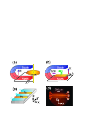
The spin dynamo we constructed is sketched in Fig. 1b and c. It is the microscopic counterpart of Faraday’s dynamo shown in Fig. 1a. Both devices generate d.c currents in a static magnetic field, but the rotational motion of a macroscopic copper plate in the Faraday’s dynamo is replaced by microscopic spin precession in the spin dynamo. The device is based on a permalloy (Py) microstrip (typically 2.45 mm 20 m 137 nm) placed in the slot between the ground (G) and signal (S) strips of a coplanar waveguide (CPW) Wen . From anisotropic magneto resistance (AMR) and ferromagnetic resonance (FMR) measurement, the following material parameters have been determined for the Py strip: the conductivity = 3 104 , the magneto anisotropy = 0.019, the saturation magnetization = 1.0 T, and the demagnetization factors 0, 0.007, 0.993. Here, is the permeability of the vacuum. The coordinate system is shown in Fig. 1c. The CPW is deposited with Au/Ag/Cr layers (5/550/5 nm) on top of a semi insulating GaAs substrate and is impedance matched to 50 . The dimensions of the CPW are 150 m and 100 m in width for the strips and the slots, respectively. As sketched in Fig. 1b, setting the device in an electromagnet and feeding the CPW with microwaves using a conventional microwave power generator, d.c. currents are generated in the Py strip at room temperature. To preserve the symmetry of the CPW, two identical Py microstrips are inserted in both slots. They are measured independently, and the same effect is found. Several spin dynamos with different Py thickness have been measured in various configurations. The data reported here have been rendered, both experimentally and theoretically, to convey the most significant aspects of the observed phenomena. For the same purpose, a special sample holder has been constructed that enables the spin dynamo to rotate about both and -axes with an angular resolution approaching 0.01 degree.
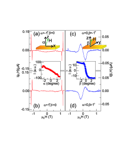
Fig. 2 demonstrates the production of bipolar d.c. currents from the Py strip under microwave radiation. The microwave frequency is set at 5.4 GHz. The current flowing along the -axis is measured using a current amplifier while sweeping the magnetic field applied nearly perpendicular to the Py strip. We define and as the small angles of the field direction tilted away from the -axis towards and axes, respectively. As shown in Fig. 2a, when is set to zero, the current measured at = -1∘ shows a positive peak and a negative dip. The current rapidly diminishes when is tuned to zero, and then changes polarity when becomes positive (Fig. 2b). The same bipolar behaviour holds true for the current measured at = 0 and plotted in Figs. 2c and d, except that its polarity also changes upon reversing the direction of the applied magnetic field. In addition, the sharp features in Figs. 2a and b disappear in Figs. 2c and d. The insets in Fig. 2 summarize the angular dependence of the maximum bipolar current, measured by using standard lock-in techniques to enhance the signal/noise ratio at extremely small angles. The curious results of Fig.2 can be summarized with the following observed bipolar symmetry:
| (1) | |||
| (2) |
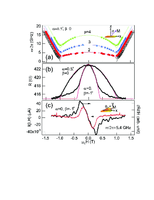
The sharp features in the trace observed in Figs. 2a and b suggest a resonant nature, which is confirmed by frequency dependence measurements. At higher frequencies, up to four resonances are observed. For , the measured resonant relations, plotted in Fig. 3a, follow the dispersion of standing spin waves (SSW) in Py films Morrish , given by . Here, is the wave vector with the values of determined by the number of half wavelength in the Py strip with a thickness . The solid lines in Fig. 3a are calculated using a gyromagnetic ratio GHz/T and an exchange constant = 1.22 10-11 N for Py Morrish . Four modes with = 0, 2, 3, and 4 are determined from the observed resonances, which indicates an intermediate pinning condition Puszkarski . With , the dispersion for SSW was previously unclear, due partially to the experimental challenge of detecting spin waves in a single Py microstrip. However, a similar field curve with a sharp cusp corresponding to the magnetic anisotropy was observed for the FMR Vonsovskii . Here, in the situation with = 0, rotates with increasing from the easy axis parallel to the -axis towards the direction of . When is small, we find the solution of the magnetostatic problem gives where the angle shown in Fig. 3a describes the direction of with respect to the hard -axis. This simple relation is confirmed by the AMR measured at = 0, plotted in Fig. 3b, which is well represented by . By noticing the apparent similarity between the measured SSW dispersion and the AMR trace shown in Figs. 3a and b, respectively, we suggest an empirical expression describing SSW at , given by , which well describes the measured dispersions.
It follows therefore that the spin dynamo is an ideal device for electrically detecting spin resonances in FM microstructures. In order to focus on the origin of the spin rectification effect, we leave the interesting physics of spin waves in the spin dynamo to a later paper and continue here by studying measured at = 0. Since in this case is tilted towards the -axis by a small angle , and because for the long Py strip, we make an approximation to simplify the otherwise complicated magnetostatic problem. With increasing , we assume rotates first from the easy -axis towards the -axis, before it moves out of the plane towards the direction of . Physically this means the Py strip is much easier to magnetize along the -axis than the -axis. By describing the direction of with the angle measured with respect to the -axis as shown in Fig. 3c, we find for , and 0 for , where . As shown in Fig. 3b, our approximation is justified by the AMR trace measured at = 0 and -1∘, which agrees well with the curve calculated from for 0.4 T. In this field range, we find that the current partially follows . This comparison is shown in Fig. 3c.
All of these results indicate that the current is induced by the dynamics of , the equilibrium direction of which is determined by the angles and at , and and at . These results imply that the electric and magneto response in the spin dynamo are coupled, as demonstrated by the following arguments on the nature of the spin rectification effect.
It is well known that under internal magnetic () and electric () fields, the magnetostatic response of the Py strip is determined by via the static permeability tensor , while the electrostatic response is described Jan by the generalized Ohm’s equation . This equation takes into account spin-charge coupling effects phenomenogically via the nonlinear terms. Here the second term describes magnetoanisotropy via the AMR coefficient , which we have used to calculate the AMR trace . The last two terms describe the Hall effect with the ordinary and extraordinary Hall coefficient given by = -1.9 10-8 cm/T and 3.3 10-8 cm/T, respectively Foner . Dynamically, the magneto and electro responses of the Py strip to the RF magnetic () and electric () fields are given by and , respectively. Here, the high-frequency permeability and conductivity tensors and determine the dynamic spin accumulation and the eddy current , respectively. If static and dynamic fields coexist, the nonlinear effects couple not only the magneto and electric response, but also the static and dynamic ones. Solving the equations for both static and dynamic response self consistently, we obtain the d.c. current density in the absence of the applied static electric field as
| (3) |
where is determined by the time average Juretschke of the product of and .
Eq. (2) is the general expression for the spin-rectification effect in FM. Taking into account the large electric and magneto anisotropy of the Py microstrip, the measured current density in our spin dynamo is obtained:
| (4) |
Since the components of are described by the angles , , and defined before, it is straight forward to show that if = 0, for , and for . When = 0, for , and for . From these results, the bipolar symmetry deduced for and is exactly the same as summarized in Eq. (1). The result for explains the disappearance of the sharp resonances in Figs. 2c and d. Note that for , is quasi-resonant which combines the resonant nature of and a nonresonant linear dependence on . It is easy to show that saturates at about at small angles and follows in the field dependence, which agree well with the experimental results shown in Figs. 2 and 3, respectively. Terms related to and cause more complicated features in , and are neglected here for brevity.
It is clear therefore that the spin rectification effect, which generates d.c. currents via spin dynamics, is analogous to the optical rectification effect. The effect appears whenever spin and charge responses mix via nonlinear responses. In semiconductors, spin-orbit coupling may affect such a mixing Ganichev ; Yang . In FM, the effect is nonzero due to spin-charge coupling effects. It should be noted that a few earlier works Juretschke ; Egan have analyzed to a great detail special features of a dc effect induced by FMR in FM thin films. Here in this work, Eq. (2) gives a more general solution to the generalized Ohm’s equation, and the new expression of Eq. (3) describes the spin-induced currents in FM microstrips. Experimentally, in contrast to earlier works Juretschke ; Egan where only a pulsed voltage signal resonantly induced by FMR was recorded by using a high-power (up to kW’s) pulsed microwave source, we are able to directly measure two distinct types of d.c. currents, i.e., induced resonantly by both FMR and SSW, and caused quasi-resonantly by the combination of AMR and the spin excitations. These currents with different characteristics show an intriguing bipolar symmetry which is well explained by Eq. (3). All these striking new results are pivotal for clarifying the spin pumping effect Costache ; Azevedo . And they are achieved due to the exceptional technical advance of the novel spin dynamo, which is significantly different from the devices used earlier Juretschke ; Egan . The spin dynamo based on the lateral seamless combination of a FM microstrip with the CPW strip lines is also of significant technical importance, since it can be easily integrated with modern planar technologies.
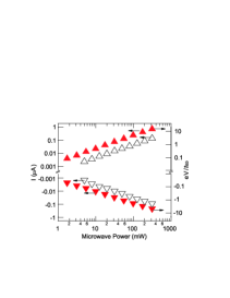
It follows from Eq. (3) that the spin rectification effect is proportional to the microwave power. This is confirmed in Fig. 4 where the results for two spin dynamos measured over a power range varying by three orders of magnitude are plotted. Compared to earlier studies on semiconductors Ganichev and FM films Egan , the current and voltage/power sensitivity have been increased by three orders of magnitude, reaching values as high as 1 A/W and 1 mV/W, respectively. Experimental data obtained from a number of spin dynamos show that the power sensitivity depends on the material parameters, device geometries, and measurement configurations. The unprecedented high power sensitivity achieved and shown in Fig. 4 is by no means the final limit. To further increase it, one should solve the Maxwell equations together with the Landau-Lifschitz equation under different boundary conditions, in order to enhance the efficiency of the microwave coupling by further optimizing the detailed device design. It is also interesting to compare the spin dynamo with the spin battery recently proposed for magnetic bilayers Brataas ; Tserkovnyak . In the spin battery, a d.c. voltage generated by FMR was predicted to occur via the spin pumping effect, with a universal high power limit given by . In contrast, the ratio of the spin dynamo reaches values approaching 18, and shows no evidence of saturation. This indicates that the voltage contribution per photon in the spin dynamo is more than one order of magnitude larger than that predicted for the spin battery. We anticipate that the difference is caused by lateral spin transport in the spin dynamo, which was neglected for spin battery design based on interfacial spin transport Brataas ; Tserkovnyak . Since the characteristic length scale of the spin transport in FM is only about a few nanometers, experimental attempts Costache ; Azevedo to test spin battery are facing the challenge of distinguishing effects caused by lateral and interfacial spin transports. Results of this work provide new solutions. It should be emphasized that the d.c signal generated from the FM strip, as shown in Fig. 2, may reverse its sign and change the order of its magnitude by tilting the device through only a few tenths of a degree.
In summary, we have demonstrated a spin rectification effect which generates d.c currents via spin wave excitations. The unprecedented high power sensitivity and the intriguing bipolar symmetry may enable new RF signal procession and sensor applications utilizing spin dynamics. By highlighting the analogy between spin and optical rectification effects, we have not only achieved a clear understanding of the spin rectification effect in the FM strip, but also provided a more general and consistent view for interpreting spin-driven currents, which is currently of great interest and have been studied in a variety of materials.
We thank G. Roy and G. Mollard for technical assistance, D. Heitmann, U. Merkt and DFG for the loan of equipment. N.M. is supported by a DAAD scholarship. This work has been funded by NSERC and URGP grants awarded to C.M.H.
References
- (1) A.A. Tulapurkar, et al., Nature 438, 339 (2006).
- (2) J.C. Sankey, et al., Phys. Rev. Lett. 96, 227601 (2006).
- (3) S.D. Ganichev, et al., Nature 417, 153 (2002).
- (4) C.L. Yang, et al., Phys. Rev. Lett. 96, 186605 (2006).
- (5) C.-M. Hu, C. Zehnder, Ch. Heyn, and D. Heitmann, Phys. Rev. B 67, 201302(R) (2003).
- (6) Y.S. Gui, S. Holland, N. Mecking, and C.-M. Hu, Phys. Rev. Lett. 95, 056807 (2005).
- (7) M.V. Costache,et al., Phys. Rev. Lett. 97, 216603 (2006); J. Grollier,et al., J. Appl. Phys. 100, 024316 (2006).
- (8) A. Azevedo, et al., J. Appl. Phys. 97, 10C715 (2005); E. Saitoh, et al., Appl. Phys. Lett. 88, 182509 (2006).
- (9) C.P. Wen, IEEE Trans. Microwave Theoy Tech. MTT-17, 1087 (1969).
- (10) A.H. Morrish, The Physical Principles of Magnetism, (IEEE Press, New York, 2001).
- (11) H. Puszkarski, Prog. Surf. Sci. 9, 191 (1979).
- (12) S.V. Vonsovskii, Ferromagnetic Resonances, (Pergamon, 1966), p. 38 and 39; O. Mosendz et al., J. Magn. Magn. Mater. 300, 174, (2006).
- (13) J.P. Jan, in Solid State Physics, Vol. 5. edited by F. Seitz and D. Turnbull (Academic Press, Inc., New York, 1957).
- (14) S. Foner, Phys. Rev. 99, 1079 (1955).
- (15) H.J. Juretschke, J. Appl. Phys. 31, 1401 (1960).
- (16) W.G. Egan, H.J. Juretschke, J. Appl. Phys. 34, 1477 (1963).
- (17) A. Brataas, et al., Phys. Rev. B 66, 060404(R) (2002).
- (18) Y. Tserkovnyak, et al., Rev. Mod. Phys. 77, 1375 (2005).