Current affiliation: ]Information Technology Laboratory, National Institute of Standards and Technology, Gaithersburg, MD, 20899
Challenges in continuum modeling of intergranular fracture
Intergranular fracture in polycrystals is often simulated by finite elements coupled to a cohesive-zone model for the interfaces, requiring cohesive laws for grain boundaries as a function of their geometry. We discuss three challenges in understanding intergranular fracture in polycrystals. First, 3D grain boundary geometries comprise a five dimensional space. Second, the energy and peak stress of grain boundaries have singularities for all commensurate grain boundaries, especially those with short repeat distances. Thirdly, fracture nucleation and growth depends not only upon the properties of grain boundaries, but in crucial ways on edges, corners, and triple junctions of even greater geometrical complexity. To address the first two challenges, we explore the physical underpinnings for creating functional forms to capture the heirarchical commensurability structure in the grain boundary properties. To address the last challenge, we demonstrate a method for atomistically extracting the fracture properties of geometrically complex local regions on the fly from within a finite element simulation.
The nucleation and propagation of cracks in practical engineering materials depends strongly on the mesoscopic structure; grain boundaries, polyphase inclusions, dislocations and other defects determine the toughness. Can continuum computational modeling be used to quantitatively study such complex failure modes?
Consider brittle intergranular fracture—rupture at the boundary between two crystallites. Ignore for the moment problems like embrittlement caused by impurity segregation to grain boundaries, and assume a clean, single-phase, equilibrium grain boundary. Direct atomistic simulations are infeasible for anything larger than nanocrystals; even simulations that focus on the boundaries Quasicontinuum will be overwhelmed by the number of relevant atoms for systems larger than microns in scale. Hence let us imagine a finite-element simulation of the polycrystal coupled to, say, cohesive-zone models for each interface needleman-interfaceCZM ; xu-needleman ; camacho-ortiz ; tvergaard-hutchinson . (A cohesive law gives the crack opening as a function of the traction across the interface; it is often parameterized by a peak stress and a total energy associated with cleaving cube-in-cube .) Can one use atomistic models to measure the fracture properties of the individual boundaries, and then use these properties in a realistic continuum fracture simulation? We outline here some serious challenges involved in continuum modeling of intergranular fracture; complete details are available in longer publications grain-boundary-geo ; cube-in-cube .
The first challenge is that of geometrical complexity. The cohesive law will depend on the structure of the grain boundary. The macroscopic geometry of a 3D grain boundary depends on five parameters that describe the relative orientations of the two grains. (The fracture dynamics may in principle depend on properties of the crack that are not treated explicitly by the cohesive zone model, such as the orientation of the crack front within the grain boundary or the three separate stress intensity factors.) The atomistic structure also depends on how the two crystal lattices are translated with respect to one another along the three directions, which can greatly affect the pattern of atoms along the boundary and hence the peak stress and energy grain-boundary-geo . One particular shift will constitute a global energy minimum corresponding to the most natural configuration grain-boundary-geo .
In a polycrystal, one grain will have to find an energy minimizing configuration with several other, neighboring grains. For a particular grain boundary in a polycrystal, where each grain has been pinned by other neighboring grains, there will be a competition between elastic straining and plastic deforming. For thick grains, in equilibrium, and away from intersections, one can show that it is advantageous for the crystallites to strain slightly to allow the boundary to find the global energy minimum.
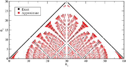
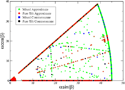
To compute the cohesive properties of grain boundaries efficiently, it is useful to use periodic boundary conditions in directions perpendicular to the grain boundary, which demands that the the two crystals have finite repeat distances along the interface, and that the repeat distances be commensurate with one another. We have found a systematic method of finding commensurate grain boundaries grain-boundary-geo , and have also generalized it to allow for slight elastic strains to mesh the two crystal boundaries together. We can approximate commensurate grain boundaries by allowing small strains in either direction. Fig. 1 describes the commensurate grain boundaries for 2D hexagonal crystals; Fig. 2 shows a cross section of the five dimensional space of commensurate and near commensurate grain boundaries for three-dimensional FCC crystals.
These commensurability questions are not only of practical importance in efficiently computing the properties of grain boundaries; commensurate grain boundaries (especially those with short repeat distances) also have especially low energies and high peak stresses grain-boundary-geo ; wolf-book . Modeling the geometry dependence of the peak stress and energy could be relatively straightforward if they depended in comprehensible ways on the five geometrical parameters. The second challenge in continuum models of fracture is to incorporate the singularities associated with commensurate geometries into appropriate functional forms.
It is well established that cusp singularities in the energy occur at special high-symmetry grain boundaries with low repeat distances grain-boundary-geo ; sansoz-molinari-structure ; chen-GB ; wolf-book ; old-gb-book . The cusps in energy can be understood by thinking of a high-symmetry boundary as an undeformed reference crystal grain-boundary-geo . Nearby grain boundaries (whose crystallites are rotated by a small angle from the high-symmetry boundary) are thus described by decorating the high-symmetry boundary with a few extra dislocations, just as a low-angle grain boundary in a crystal can be described as an array of well-separated dislocations. This analogy leads to a functional form for grain boundary energy as a function of tilt angle in which the cusps around the special high symmetry grain boundaries have the same form as low angle grain boundaries grain-boundary-geo . Fig. 3 shows the results for a systematic study of symmetric 2D grain boundaries and the resulting fitting function grain-boundary-geo .
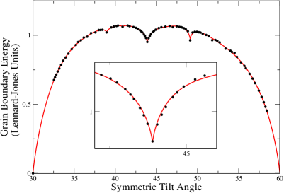
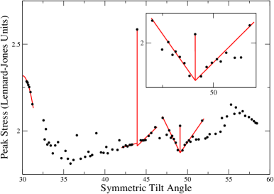
For the peak stress, it is known that there are jumps at the same special grain boundaries chen-GB ; wolf-book ; grain-boundary-geo . We can also understand these jumps by using the dislocation picture described above grain-boundary-geo . As we add a dislocation to the high symmetry grain boundary, we add a nucleation point for fracture, causing a discontinuity in the peak stress. As a result, the plot of peak stress vs. tilt angles is discontinuous at every commensurate geometry (Fig. 3). By considering the elastic interaction between the extra dislocations, we have been able to understand also the dependence of the peak stress in the vicinity of the high-symmetry boundaries (see Fig. 3 and grain-boundary-geo ).
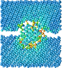
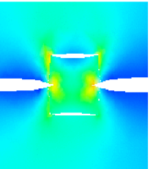
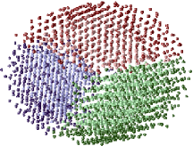
Are cohesive laws enough? We have studied this question computationally cube-in-cube by comparing a direct atomistic simulation of polycrystalline fracture with a finite-element simulation of the same geometry using cohesive-law parameters derived from the same interatomic potential. Fig. 4 shows a snapshot of the two simulations of polycrystalline fracture in Stillinger-Weber silicon. Both in this case and for other simulations, the atomistic simulations fail at significantly lower stresses than the continuum simulations. Crack nucleation in both atomistic and continuum simulations happens not in the middle of grain boundaries, but at triple junction lines, edges, and corners which are not quantitatively described by the cohesive laws for the grain boundary interfaces. Similarly, quantitative understanding of how the crack turns, branches, or goes intragranular (Fig. 4) at triple junctions demands that we understand the effects of the irregular atomistic configurations at these junctions.
The third challenge is thus to develop an effective computational method for modeling more complex local geometries. One in principle could incorporate an analytical understanding of these local geometries into, for example, cohesive laws for triple junctions, but the geometrical complexity would seem daunting. Can one rely here on direct atomistic simulations? Brittle crack nucleation is a local phenomenon, and the intersection of a growing crack with a triple junction edge again will generically happen at a point. A feasible atomistic simulation of the local region of interest could be launched whenever the continuum simulation reached a stress state where its cohesive laws become unreliable. The information about the local geometry (elastic strains, grain orientations, and impinging crack surfaces) would be transferred from the continuum simulation to generate the atomistic configuration, and the results of the atomistic simulation (nucleation thresholds, crack branching and turning events) passed back to the finite-element simulation.
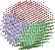
As an example of such a method, Fig. 5 shows an Overlapping Finite Elements and Molecular Dynamics (OFEMD) simulation of fracture at a triple-junction, generated automatically in this fashion cube-in-cube . The grains were generated using geometry, orientation, and boundary strains passed from a finite element simulation, running on a separate machine and communicating either through a command-line interface, a Web service, or a database. OFEMD uses the DigitalMaterial DigitalMaterial atomistic simulation environment to deform and relax the atomistic coordinates, allowing the failure information to be recorded. OFEMD can be downloaded from url:OFEMD .
We have discussed three main challenges involved in continuum modeling of polycrystal fracture. First, exploring the cohesive properties of 3D grain boundaries involves exploring a 5D space. Second, the peak stress and energy have singularities at all commensurate grain boundaries. Even if it weren’t for the first two challenges, our comparisons of atomistic and finite element simulations of polycrystal fracture show that cohesive properties of the interfaces alone are not enough to model the fracture of polycrystals using continuum methods. Sites such as triple junctions, edges, and corners of grains are important nucleation sites. In order to resolve this last challenge, we suggest the use of direct atomistic modeling of local regions of interest.
Acknowledgements.
This work was supported by NSF Grants No. ITR/ASP ACI0085969 and No. DMR-0218475. We also wish to thank Drew Dolgert, Surachute Limkumnerd, Chris Myers, and Paul Wawrzynek.Competing financial Interests
The authors declare no competing financial interests.
References
- 1 Shenoy, V. B., Miller, R., Tadmor, E. B., Rodney, D., Phillips, R., and Ortiz, M. Journal of the Mechanics and Physics of Solids 47, 611–642 (1999).
- 2 Needleman, A. Journal of the Mechanics and Physics of Solids 38(3), 289–324 (1990).
- 3 Xu, X. P. and Needleman, A. Journal of the Mechanics and Physics of Solids 42(9), 1397–1434 (1994).
- 4 Camacho, G. T. and Ortiz, M. International Journal of Solids and Structures 33, 2899–2938 (1996).
- 5 Tvergaard, V. and Hutchinson, J. W. Journal of the Mechanics and Physics of Solids 40(6), 1377–1397 (1992).
- 6 Coffman, V. R. and Sethna, J. P. (2008), submitted, http://arxiv.org/abs/0707.1060.
- 7 Coffman, V. R., Sethna, J. P., Heber, G., Liu, A., Ingraffea, A., and Barker, E. I. (2008), submitted, http://arxiv.org/abs/0803.1003.
- 8 Wolf, D., editor. Materials Interfaces: Atomic-level structure and properties. Chapman & Hall, (1992).
- 9 Sansoz, F. and Molinari, J. F. Acta Materialia 53, 1931–1944 (2005).
- 10 Chen, S. P., Srolovitz, D. J., and Voter, A. F. Journal of Materials Research 4, 62 (1989).
- 11 Chadwick, G. A. and Smith., D. A., editors. Grain Boundary Structure and Properties. Academic Press Inc., London, (1976).
- 12 Bailey, N., Cretegny, T., Sethna, J. P., Coffman, V. R., Dolgert, A. J., Myers, C. R., Schiotz, J., and Mortensen, J. J. (2006), submitted, http://arxiv.org/abs/cond-mat/0601236.
- 13 Coffman, V. R. and Bailey, N. http://www.lassp.cornell.edu/sethna/DM/mdwebservices/.