Slippage of Newtonian liquids: influence on the dynamics of dewetting thin films
Abstract
Slippage of Newtonian liquids in the presence of a solid substrate is a newly found phenomenon the origin of which is still under debate. In this paper, we present a new analysis method to extract the slip length. Enhancing the slip of liquids is an important issue for microfluidic devices that demand for high throughput at low pumping power. We study the velocity of short-chained liquid polystyrene (PS) films dewetting from non-wettable solid substrates. We show how the dynamics of dewetting is influenced by slippage and we compare the results of two types of substrates that give rise to different slip lengths. As substrates, Si wafers were used that have been coated by octadecyltrichlorosilane (OTS) or dodecyltrichlorosilane (DTS), respectively. Our results demonstrate that the dewetting velocity for PS films on DTS is significantly larger than on OTS and that this difference originates from the different slip lengths of the liquid on top of the two surfaces. For PS films of thicknesses between 130 nm and 230 nm we find slip lengths between 400 nm and 600 nm, depending on substrate and temperature.
I Introduction
Thin films of liquid polymers play an important role in numerous technological processes ranging from lithography to biological membranes Oro97 . A key to understanding the stability of, e.g., liquid coatings on solid surfaces was the calculation Vri66 ; Ruc74 ; Sha85 ; Die88 ; Sch89 and the experimental derivation of the effective interface potential Rei92 ; Sfe98 ; Kim99 ; See01 ; See01-2 ; See01-3 . In recent years, one major focus of interest has been to understand the dynamics and morphology of polymer films dewetting from non-wettable substrates Red91 ; Red94 ; Bro94 ; Bro97 ; Mas02 ; Dam03 ; Rei01 ; Vil06 ; Jac98 ; Rei00 ; See01-4 ; Bec03 ; Net03 ; Fet05 ; Vil05 . The dewetting rate of the liquid hereby strongly depends on the flow velocity at the solid/liquid interface. Hitherto it was common sense that the occurrence of a non-zero flow velocity (slippage) at the interface is restricted to high molecular weight polymer films Gen85 . Only recently, new experimental techniques have revealed that also Newtonian liquids may exhibit slippage Pit00 ; Sch05 ; Cot02 ; Leg03 . The occurrence and the nature of slippage is of large technological interest, since a sliding fluid can flow faster through, e.g., microfluidic devices.
Many studies have focused on techniques to measure slippage. These approaches can be classified in direct and indirect methods to determine the fluid velocity profile near the solid/liquid interface. Direct methods use, e.g., tracer particles in combination with near-field laser velocimetry Leg03 ; Herv03 or fluorescence recovery after photobleaching techniques Pit00 ; Sch05 ; Mig93 . Indirect methods aim at measuring the drainage force of an object moved in a liquid to calculate the amount of slippage. Common techniques use a surface forces apparatus Cot02 ; Zhu02 or an atomic force microscope (AFM) with a colloidal probe Cra01 . For details see, e.g., the review articles from Lauga et al. Lau05 or Neto et al. Net05 .
A common measure of slippage is the slip length, which can be understood as the length below the solid/liquid interface where the velocity extrapolates to zero. For simple fluids, the slip length is found to be independent of the shear rate Herv03 ; Pri04 , but is influenced by the wettability of the substrate as well as by the roughness of the wall: Molecular dynamics simulations for a simple liquid with 140∘ contact angle on the surface of interest found a slip length in the order of 30 diameters of the fluid molecules, but no-slip boundary condition for a wetting situation Bar99 . This result is in agreement with experimental data of hexadecane Pit00 ; Sch05 ; Herv03 or glycerol Cot02 . The role of surface roughness is ambiguous: simulations revealed that, depending on the pressure, surface roughness can increase or decrease the amount of slippage Cot03 ; experiments demonstrated the importance of the lateral length scale of the roughness Leg03 ; Jos06 .
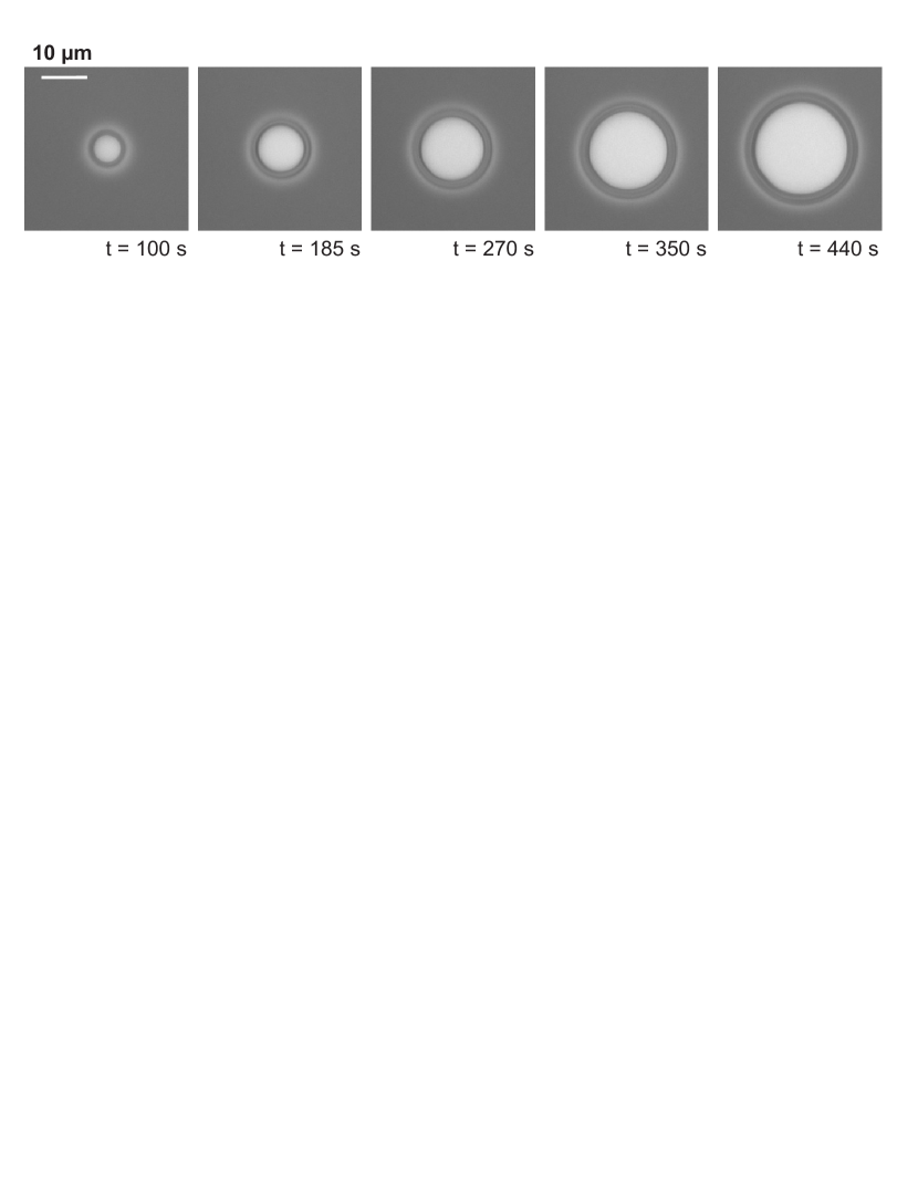
In our studies, we investigate the dewetting process of thin liquid films, a typical scenario is depicted in Fig. 1. In order to extract the slip length, we develop a new method for the analysis of the dewetting rates. Dewetting can be described in three different stages Bro97 , starting from the very beginning of hole formation. In the first stage, the dewetted region grows exponentially in time and, in the vicinity of the dry area, a homogeneous thickening of the film can be observed; the hole does not yet exhibit a rim. In the second regime, the ’birth’ of the rim takes place. In this stage, the rim has an asymmetric shape, and the radius grows linearly in time. In the third stage of dewetting, which starts at radii in the order of the slip length, surface tension rounds the rim which becomes more symmetric and grows from now on in a self-affine manner. Many experiments confirm this three-stage dewetting scenario Mas02 ; Dam03 ; Rei01 ; Vil06 .
In the third stage of a ’mature’ rim, slippage is found to influence the dynamics in a substantial way Red94 ; Bro94 : For the case of a no-slip boundary condition or negligible sliding friction at the solid/liquid interface, viscous dissipation (which occurs dominantly in the vicinity of the three phase contact line) results in a linear growth of holes; if, however, dissipation at the solid/liquid interface dominates the dewetting process, an power law is expected. For the latter case of large slippage, the third stage might be followed by a forth regime, when the rim height is large as compared to the slip length Bro94 . In this case, sliding dissipation again can be neglected and a linear growth is expected.
In our studies we are interested in the stage of a mature rim that grows in a self-affine manner in width and height. In the following we will demonstrate how we can deduce the slip length from the dynamics of the hole growth. We hereby restrict ourselves to liquids of Newtonian behavior and therefore investigate only the dewetting dynamics of short-chained polymer melts below the entanglement length. A short glance on Fig. 3 reveals that the growth law for the hole radius is clearly non-linear. We therefore suppose that slippage cannot be neglected. On the other hand, the polymer melt is not entangled. Hence, slippage is not expected to dominate the growth of holes at any stage. In the theoretical section we will describe a model assuming that neither viscous dissipation at the contact line nor sliding friction at the solid/liquid interface entirely dominates the dynamics. We rather propose that the two different dissipation mechanisms are balanced and both have to be taken into account simultaneously Jac98 .
II Experimental Section
For the experiments, atactic polystyrene (PS, by Polymer Standard Service, Mainz, Germany) with a molecular weight of 13.7 kg/mol and a polydispersity of was used. The samples were prepared by spin casting a toluene solution of PS onto mica, floating the films on MilliporeTM water, and then transferring them to hydrophobic substrates. For the hydrophobization, we used two different self-assembled monolayer coatings on top of Si wafers (2.1 nm native oxide layer), octadecyltrichlorosilane (OTS) and the shorter dodecyltrichlorosilane (DTS), respectively, prepared by standard techniques Was89 . By ellipsometry (EP3 by Nanofilm, Göttingen, Germany), the thickness of the SAMs was found to be nm and nm, respectively. Surface characterization by atomic force microscopy (AFM, Multimode by Veeco, Santa Barbara, USA) revealed an RMS roughness of 0.09(1) nm (OTS) and 0.13(2) nm (DTS) at a m scan size, and a static contact angle of polystyrene droplets of on both coatings. The surface tension of polystyrene is mN/m.
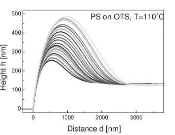
The polystyrene films in this study are either 130(5) nm or 230(5) nm thick. To induce dewetting, the films were heated above the glass transition temperature of PS (C) to three different temperatures (C, C, C). After a few seconds, circular holes are born and instantly start to grow. An example of a typical temporal series captured by optical microscopy is shown in Fig. 1. Due to mass conservation of the liquid rims develop, surrounding each hole. Cross sections of such a growing rim are shown in Fig. 2, as measured by in situ AFM. The dynamic contact angle of the liquid is and stays constant during dewetting.
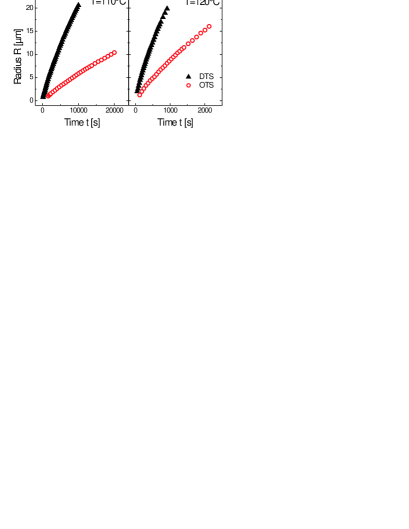
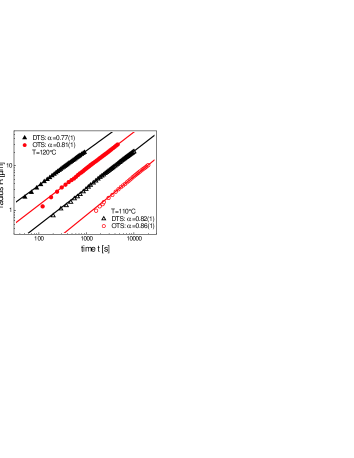
In Fig. 3, the optically measured radii of the emerging holes in the PS(13.7k) films as a function of time are depicted for two temperatures and the two types of silane substrate. Firstly, for each series, we find a non-linear growth law. To emphasize this, the data are additionally drawn in Fig. 4 in a logarithmic diagram, revealing an algebraic growth of the radius in time with an exponent of . Secondly, dewetting progresses clearly faster on DTS than on OTS coated substrates.
We qualitatively interpret this observation as follows. At the same temperature the polymer films on both samples have identical properties: the viscosity as well as the surface tension do not depend on the substrate underneath. Additionally, the static contact angle of polystyrene on both surfaces is constant within the experimental error. Therefore, the spreading coefficient N/m which is the driving force of the dewetting process is identical on OTS and on DTS substrates. The only parameter that could be different is the boundary condition at the solid/liquid interface of the two substrate. Since dewetting on DTS is much faster than on OTS, we expect a significantly larger slip length for PS(13.7k) on the DTS coating.
III Theoretical Section: Energy dissipation models
To get more insight in the mechanisms involved in the dewetting process, a detailed analysis of the velocity is required. The velocity of the moving front is given by the force balance between the driving force and the power dissipated in the dewetting process, . Assuming no slip at the solid/liquid interface, energy is dissipated by viscous friction only within the liquid volume and at the three phase contact line. Since the highest shear rates arise in the vicinity of the contact line, viscous dissipation takes place dominantly at this line and is therefore independent of the size of the rim. However, is influenced by the flow geometry near the contact line, i.e., by the dynamic contact angle . Thus, the dewetting velocity is given by
| (1) |
with the viscosity of the liquid, and a function of the dynamic contact angle that counts for the flow geometry Bro94 .
As shown in Fig. 2, the dynamic contact angle is temporally constant in our experiments. Thus, viscous dissipation does neither depend on hole size nor on time. On the other hand, the driving force does not vary during the dewetting process. Hence, in the model of no-slip boundary condition, the dewetting velocity is constant, and the radius grows linearly in time, , which holds for Newtonian liquids as shown, e.g., in Ref. Red91 .
Since the data in Fig. 3 clearly do not show a linear growth of the radius , but rather a decreasing velocity, our experiments do not allow the assumption of a no-slip boundary condition.
Another model, the so-called ’full-slip’ or ’plug flow’ model, introduced to explain the dewetting rate of entangled polymer melts, assumes large slip lengths at the solid/liquid interface Bro94 . Here, energy dissipation dominantly occurs at this interface over the distance of about the width of the rim, . Hence, the power dissipated in the dewetting process is proportional to , and force balance results in the velocity ,
| (2) |
with the slip length . Self-similarity of the growing mature rim, (which means a constant dynamic contact angle, c.f. Fig. 2), and mass conservation of the liquid yields . Hence, in this model, the velocity decreases with increasing hole size, , and the hole radius increases algebraically in time with an exponent , . For simplicity, we can introduce the constant number and write .
Although the data in Fig. 4 show an algebraic behavior , the exponents fitted to the data achieve values clearly above 2/3; the mean value of the exponents of the four curves shown in Fig. 4 is . Hence, the model of full slippage also is not adequate to describe our experimental results.
Another model combining energy dissipation at the three phase contact line and sliding dissipation at the solid/liquid interface is required. In literature there are some suggestions of a transition within the dewetting process, meaning that at an early stage viscous dissipation at the contact line dominates the dynamics of dewetting, , while in a later stage the holes grow mostly due to slip effects, Bro97 ; Mas02 ; Dam03 . In our experiments, for some small holes, we can see such a transition from an early stage of almost constant dewetting velocity to a later stage of decreasing velocity. Nevertheless, the model of slip-dominated dissipation is not appropriate for the experimental data, even not at the later stage.
In our earlier study, Ref. Jac98 , simple addition of both contributions of the dewetting velocity is suggested (’combined model’),
| (3) |
with and . Separation of the variables yields the function
| (4) | |||||
Unfortunately, this implicit equation for the radius is rather cumbersome. Since it can be fitted to any data of hole growth, this function is not able to critically test the combined model and its assumptions.
IV Testing the combined model
An alternative and more comprehensive way to check the combined model Eq. (3) is to plot the velocity versus . If the combined model is valid, the data points should then appear on a straight line with intercept and slope . As shown in Fig. 5, our experimental data indeed lie on such a straight line with a finite velocity extrapolating to zero, i.e., for infinitely large holes. This gives a first hint that the simple ’combined model’ is an adequate description for the dewetting rate of short chain polymer films. Just the data of small holes on DTS with radii below 4 m deviate from this line. Since the rims of these holes are not yet in the mature regime, we can neglect these data points for further analysis.
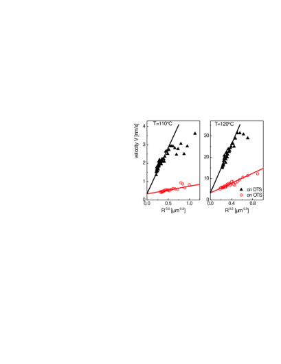
How can we further test that the combined model is indeed an appropriate description?
If the intercept represents the dewetting velocity of viscous flow, , then it should fulfill three conditions: i) the temperature dependence of should be dominated by the inverse viscosity of the polymer melt, ii) should be independent of the initial film thickness , which is a very strong condition, and iii) the intercept should only depend on the contact angle, but not on the slip length.
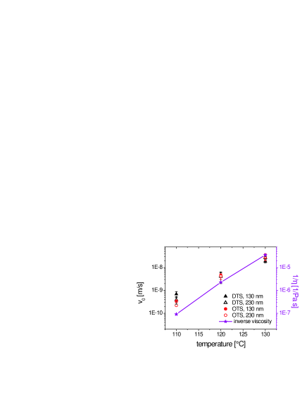
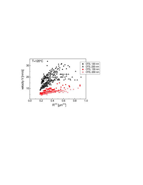
To test these three conditions, we repeated our dewetting experiments at three different temperatures and with films of two different thicknesses on both coatings DTS and OTS, cf. Fig. 6 for the experiments at 120C. As shown in Fig. 7, the extrapolated velocity increases for increasing dewetting temperature, and, moreover, the qualitative run compares well to the inverse viscosity of PS(13.7k) as measured by a rheometer. Note that viscous dissipation in the vicinity of the three phase contact line is not necessarily expected to exactly follow the behavior, since there is a contribution additionally to the shear flow that derives directly from the contact line dynamics, i.e., thermally activated jumps over an energy barrier, pinning, etc. Rui99 . Thus, the first condition for concerning the temperature dependence is satisfied sufficiently. From Fig. 7 we also learn that the initial film thickness does not systematically influence the extrapolated velocity , although the measured velocity at finite hole size does depend on film thickness, cf. Fig. 6. With this, the second condition is fulfilled. Since the intercept is independent of initial film thickness, it also does not depend on the width of the rim and, consequently, not on the effect of slippage at the solid/liquid interface. Additionally, is not influenced by the substrate, OTS or DTS covered silicon wafers, on which the PS films are supposed to show different slip lengths. This satisfies the third condition, the independence of slippage of . Note that in general depends on the substrate, since viscous dissipation is determined by the dynamic contact angle . In our experiments, however, we found the same on both substrates and, consequently, same values for . With the described tests we found all three conditions satisfied and therefore can assume that the intercept indeed compares to , which allows further analysis of the data.
V Results: The slip length
In a second step the velocity component is analyzed and the slip length is extracted. In the case of full slippage at the solid/liquid interface the velocity is given by Eq. (2), where the width of the rim reads
| (5) |
Hence, the slope shown in Fig. 5 is expected to be
| (6) |
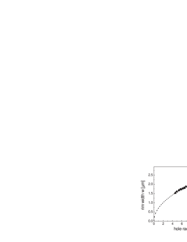
First, the validity of Eq. (5) is tested by plotting the width of the rim, , versus the hole radius , cf. Fig. 8. Here, is taken as the lateral distance between the three phase contact line () and the position where the rim height is dropped to 110% of the prepared film thickness , i.e., . Fitting Eq. (5) to the data of 130 nm and 230 nm thick PS films, we obtain on OTS and on DTS covered wafers.
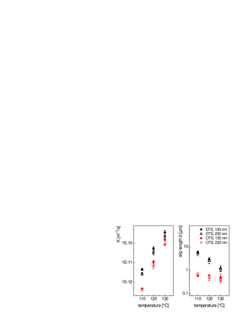
Knowing , the spreading coefficient N/m, the initial film thickness , and the viscosity of the investigated films, cf. Fig. 7, we can now use Eq. (6) to directly determine the slip length from the slope . Although the values for are affected by the film thickness, cf. Figs. 6 or 9a, this dependence is canceled out very well for the slip length, as shown in Fig. 9b. This again indicates that the combined model Eq. (2) can be used to analyze the data of our experimental system. We find decreasing for increasing dewetting temperature. Additionally, the slip length of PS(13.7k) is clearly larger on DTS than on OTS, but the difference decreases with increasing temperature, a fact that corroborates the results for the slip lengths determined by rim shape analysis Fet06 .
VI Conclusion
We have developed a new analysis method to extract slip lengths from dewetting rates. The experiments give evidence that a model has to be put forward that combines frictional energy dissipation at the interface with viscous dissipation at the three phase contact line. We show that simple addition of two different velocity components is an adequate description for highly viscous Newtonian liquids dewetting from smooth surfaces. We moreover were able to demonstrate that this description also captures a variable friction coefficient at the solid/liquid interface. The components and are given by the well known expressions derived for the limiting cases no-slip and plug flow, respectively. From the slope of velocity data plotted versus the slip length can be determined.
For short-chained polystyrene melts on OTS and DTS covered wafers we found slip lengths between 400 nm and 6 m. Slippage in this system decreases for increasing dewetting temperature. On the DTS coating the slip lengths are up to one order of magnitude larger than on OTS.
So far, we have only hypotheses for the molecular mechanisms at the solid/liquid interface that give rise to the different slip lengths on OTS and DTS covered wafers. The commonly investigated system parameters like interaction forces between solid and liquid, i.e., contact angle and long-ranged dispersion forces, or substrate roughness are identical on both types of substrate. Thus, we have no straightforward explanation. The molecular origin of slippage in our system has to be postponed to future research. The simple analysis method of dewetting rates, however, is a powerful tool that allows for extensive studies of various systems to get a comprehensive picture of slippage of simple and complex liquids.
VII Acknowledgments
We acknowledge financial support by the European Graduate School GRK 532 and by grant JA 905/3 within the DFG priority program 1164, and generous support of Si wafers by Siltronic AG, Burghausen, Germany.
References
- (1) Oron, A.; Davis, S. H.; Bankoff, S. G. Rev. Mod. Phys. 1997, 69, 931.
- (2) Vrij, A. Discuss. Faraday Soc. 1966, 42, 23.
- (3) Ruckenstein, E.; Jain, R. K. J. Chem. Soc. Faraday Trans. 1974, II, 132.
- (4) Sharma, A.; Ruckenstein, E. J. Colloid Interface Sci. 1985, 106, 12.
- (5) Dietrich, S. In Phase Transition and Critical Phenomena; Domb, C., Lebowitz, J. L., Eds.; Academic: London, 1988; Vol. 12.
- (6) Schick, M. In Liquids at Interfaces; Charvolin, J., Joanny, J. F., Zinn-Justin, J., Eds.; Elsevier Science: Amsterdam, 1989.
- (7) Reiter, G. Phys. Rev. Lett. 1992, 68, 75.
- (8) Sferrazza, M.; Heppenstall-Butler, M.; Cubitt, R.; Bucknall, D.; Webster, J.; Jones, R. A. L. Phys. Rev. Lett. 1998, 81, 5173.
- (9) Kim, H. I.; Mate, C. M.; Hannibal, K. A.; Perry, S. S. Phys. Rev. Lett. 1999, 82, 3496.
- (10) Seemann, R.; Herminghaus, S.; Jacobs, K. Phys. Rev. Lett. 2001, 86, 5534.
- (11) Seemann, R.; Blossey, R.; Jacobs, K. J. Phys.: Condens. Matter 2001, 13, 4915.
- (12) Seemann, R.; Herminghaus, S.; Jacobs, K. J. Phys.: Condens. Matter 2001, 13, 4925.
- (13) Redon, C.; Brochard-Wyart, F.; Rondelez, F. Phys. Rev. Lett. 1991, 66, 715.
- (14) Redon, C.; Brzoska, J. B.; Brochard-Wyart, F. Macromolecules 1994, 27, 468.
- (15) Brochard-Wyart, F.; de Gennes, P.-G.; Hervet, H.; Redon, C. Langmuir 1994, 10, 1566.
- (16) Brochard-Wyart, F.; Debregeas, G.; Fondecave, R.; Martin, P. Macromolecules 1997, 30, 1211.
- (17) Masson, J.-L.; Green, P. F. Phys. Rev. Lett. 2002, 88, 205504.
- (18) Damman, P.; Baudelet, N.; Reiter, G. Phys. Rev. Lett. 2003, 91, 216101.
- (19) Reiter, G. Phys. Rev. Lett. 2001, 87, 186101.
- (20) Vilmin, T.; Raphaël, E.; Damman, P.; Sclavons, S.; Gabriele, S.; Hamieh, M.; Reiter, G. Europhys. Lett. 2006, 73, 906.
- (21) Jacobs, K.; Seemann, R.; Schatz, G.; Herminghaus, S. Langmuir 1998, 14, 4961.
- (22) Reiter, G.; Khanna, R. Langmuir 2000, 16, 6351.
- (23) Seemann, R.; Herminghaus, S.; Jacobs, K. Phys. Rev. Lett. 2001, 87, 196101.
- (24) Becker, J.; Grün, G.; Seemann, R.; Mantz, H.; Jacobs, K.; Mecke, K. R.; Blossey, R. Nature Materials 2003 2, 59.
- (25) Neto, C.; Jacobs, K.; Seemann, R.; Blossey, R.; Becker, J.; Grün, G. J. Phys.: Condens. Matter 2003, 15, 3355.
- (26) Fetzer, R.; Jacobs, K.; Münch, A.; Wagner, B.; Witelski, T. P. Phys. Rev. Lett. 2005, 95, 127801.
- (27) Vilmin, T.; Raphaël, E. Europhys. Lett. 2005, 72, 781.
- (28) de Gennes, P. G. Rev. Mod. Phys. 1985, 57, 3.
- (29) Pit, R.; Hervet, H.; Léger, L. Phys. Rev. Lett. 2000, 85, 980.
- (30) Schmatko, T.; Hervet, H.; Leger, L. Phys. Rev. Lett. 2005, 94, 244501.
- (31) Cottin-Bizonne, C.; Jurine, S.; Baudry, J.; Crassous, J.; Restagno, F.; Charlaix, E. Eur. Phys. J. E 2002, 9, 47.
- (32) Léger, L. J. Phys.: Condens. Matter 2003, 15, S19.
- (33) Hervet, H.; Léger, L. C. R. Physique 2003, 4, 241.
- (34) Migler, K. B.; Hervet, H.; Léger, L. Phys. Rev. Lett. 1993, 70, 287.
- (35) Zhu, Y.; Granick, S. Phys. Rev. Lett. 2002, 88, 106102.
- (36) Craig, V. S. J.; Neto, C.; Williams, D. R. M. Phys. Rev. Lett. 2001, 87, 054504.
- (37) Lauga, E.; Brenner, M. P.; Stone, H. A. In Handbook of Experimental Fluid Dynamics; Foss, J., Tropea, C., Yarin, A., Eds.; Springer: New-York (2005); cond-mat/0501557.
- (38) Neto, C.; Evans, D. R.; Bonaccurso, E.; Butt, H.-J.; Craig, V. S. J. Rep. Prog. Phys. 2005, 68, 2859.
- (39) Priezjev, N. V.; Troian, S. M. Phys. Rev. Lett. 2004, 92, 018302.
- (40) Barrat, J.-L.; Bocquet, L. Phys. Rev. Lett. 1999, 82, 4671.
- (41) Cottin-Bizonne, C.; Barrat, J.-L.; Bocquet, L.; Charlaix, E. Nature Materials 2003, 2, 237.
- (42) Joseph, P.; Cottin-Bizonne, C.; Benoit, J.-M.; Ybert, C.; Journet, C.; Tabeling, P.; Bocquet, L. Phys. Rev. Lett. 2006, 97, 156104.
- (43) Wasserman, S. R.; Tao, Y.-T.; Whitesides, G. M. Langmuir 1989, 5, 1074.
- (44) de Ruijter, M. J.; De Coninck, J.; Oshanin, G. Langmuir 1999, 15, 2209.
- (45) Fetzer, R.; Rauscher, M.; Münch, A.; Wagner, B. A.; Jacobs, K. Europhys. Lett. 2006, 75, 638.