Electron transport through dipyrimidinyl-diphenyl diblock molecular wire: protonation effect
Abstract
Recently, rectifying direction inversion has been observed in dipyrimidinyl-diphenyl (PMPH) diblock molecular wire [J. Am. Chem. Soc. (2005) 127, 10456], and a protonation mechanism was suggested to explain this interesting phenomena. In this paper, we study the protonation effect on transport properties of PMPH molecule by first principles calculations. No significant rectification is found for the pristine diblock molecular wire. Protonation leads to conductance enhancement and rectification. However, for all considered junctions with rectifying effect, the preferential current directions are samely from dipyrimidinyl side to diphenyl side. Effect of molecule-electrode anchoring geometry is studied, and it is not responsible for the discrepancy between experiment and theory.
I Introduction
Molecular rectifier is the first example proposed for electronic device at molecular scale, aviram7477 and it is an important topic in molecular electronics. nitzan0384 ; joachim0501 Considerable experimental and computational efforts have been devoted in recent years to molecular rectification. Metzger0303 In a recent experiment on rectification of dipyrimidinyl-diphenyl (PMPH) diblock molecular wire, Morales0556 the preferential current direction was found to be able to change possibly by protonation of the dipyrimidinyl moiety. In this experiment, PMPH molecule was first co-assembled on the Au(111) substrate together with dodecane through thiol group. Then the top end of PMPH molecule was connected to a suspended gold nanoparticle, also via thiol group. By using different protect group at the two ends, the direction of the PMPH diblock molecule on the surface can be precisely controlled. The current-voltage characteristics were measured via scanning tunneling spectroscopy (STS). Without protonation, an average rectification ratio of 7.4 was observed, with the preferential current direction from the diphenyl block to the dipyrimidinyl block. After using perchloric acid in a methanol/tetrahydrofuran mixture and sodium ethoxide in methanol to protnate and deprotonate the nitrogen atom in dipyrimidinyl group, a reversible change in the rectifying direction was observed. The protonated diblock molecular wire gave an average inverse of the rectification ratio as 9.2, with current preferring to flow from dipyrimidinyl side to diphenyl side.
Unfortunately, the microscopic mechanism of this interesting experimental observation of rectification inversion remains unclear. Moreles et al. Morales0556 tried to suggest a simple model to rationalize the rectification inversion. In their model, before protonation, the intrinsic dipole moment of the diblock molecule will induce local vacuum level shift and make the highest occupied molecular orbital (HOMO) closer to electrode Fermi energy. After the molecule is protonated, the positive charge centered on the nitrogen reverses the direction of the dipole moment, which makes the lowest unoccupied molecular orbital (LUMO) becomes closer to the electrode Fermi energy. But we notice that the relative position of HOMO/LUMO comparing to the electrode Fermi level is not directly related to rectifying effect. An orbital approaching Fermi energy will typically give conductance enhancement, as we can see later, but rectification should be determined by the bias voltage response of the relevant orbitals.taylor0201 ; li0693 ; li0616
In this paper, we report a comprehensive first principles transport study on PMPH diblock molecular wire. Non-equilibrium Green’s function (NEGF) technique combined with density functional theory (DFT) is used, which has been widely used in molecular electronics and successfully applied to molecular rectification analysis. taylor0201 ; li0693 ; li0616 In the rest part of this paper, computational details are given in section II. In section III, we discuss the protonation effect on transport properties of PMPH molecule wire, with standard hollow site S-Au anchoring. Different anchoring models are discussed in section IV. At last, we conclude in section IV.
II Computational Methods
The electronic structures are described with the implementation of DFT in SIESTA program, Soler0245 which solves the Kohn-Sham equation with numerical atomic basis sets. Double- with polarization (DZP) basis set is chosen for all atoms except Au, for which single- with polarization (SZP) is used. Our test calculations indicate that using SZP basis set for Au does not effect the accuracy of our calculations. Core electrons are modeled with Troullier-Martins pseudopotentials.Troullier91 Perdew-Zunger local density approximation Perdew8148 is used to describe the exchange-correlation potential.
The electronic transport properties are calculated with NEGF technique using ATK package, Brandbyge02 ; atk in which the molecular wire junction is divided into three regions, left electrode, contact region, and right electrode. The contact region typically includes parts of the physical electrodes where the screening effects take place, to ensure that the charge distributions in the left and right electrode region correspond to the bulk phases of the same material. The semi-infinite electrodes are calculated separately to obtain the bulk self-energy. The stacking order of the electrode atomic layer is chosen with inversion symmetry for left and right electrode, which makes the supercell not periodic along the current direction. Therefore, the electrostatic potential is calculated with multigrid method instead of fast Fourier transformation. A (2 2) and (4 4) -point grid on the - plane is used for self-consistent calculation and transmission coeffecients evaluation respectively.
III Protonation Effect on Transport Properties
III.1 geometrical model of molecular junctions
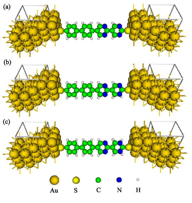
The molecular junction is modeled by sandwiching the diblock molecule between two Au(111)-(33) surfaces with thiol anchoring group. Before exploring anchoring geometry effects in the next section, we limit ourselves to the most popular hollow site adsorption first. Because the PMPH molecule is embeded in dodecanethiol self-assembly monolayer (SAM) in experiment, Morales0556 the lower pyrimidinyl ring should highly unlikely be protonated. So, we only consider protonaton for one or both of the two nitragon atoms within the top pyrimidinyl ring. The resulted molecular junctions are called monoprotonated PMPH (MP-PMPH) and diprotonated PMPH (DP-PMPH).
Fig. 1 shows the optimized geometries for the three molecular junctions with and without protonation. Only one unit cell of the semi-infinite left/right electrode, which contains three Au layers, is plotted. The dangling bonds shown in the figure indicate the periodic boundary condition (PBC) in - plane and semi-PBC for electrodes in direction. In the contact region, two Au layers at both left and right sides are included, of which the most left/right layer is constrained to its theoretical bulk geometry to match the structure of the Au(111) surface. The rest of the contact region is fully optimized. The distance between the left and right electrodes is determined by a serial of optimization calculations with different fixed electrode-electrode distances.
III.2 transmission and current-voltage characteristics
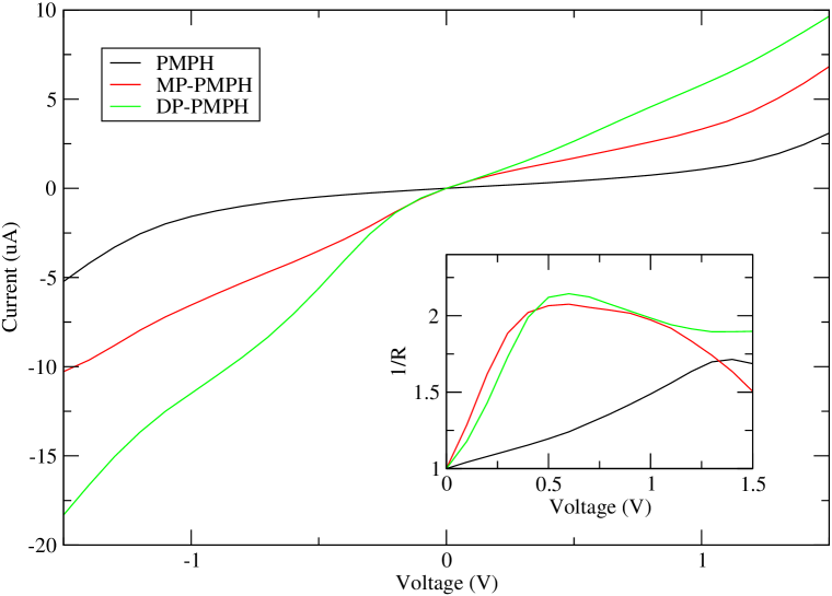
Based on the optimized geometries, the current-voltage (-) curves for PMPH, MP-PMPH, and DP-PMPH junctions have been calculated self-consistently, as shown in Fig. 2. Almost symmetric currents through PMPH molecular wire are obtained for positive and negative bias voltages, especially at low magnitudes of bias voltage. However, obvious asymmetric currents are observed for MP-PMPH and DP-PMPH, for which negative bias leads to larger current. The asymmetry of the - curves can be measured by rectification ratio (), which is define by . In the inset of Fig. 2, we plot inverse of as a function of bias voltage magnitude for all these three junctions. approaches to 1 at low bias voltage for all these three junctions, which means that the slope of I-V curve does not change abruptly at zero bias. Although the rectification ratios for MP-PMPH and DP-PMPH are distinguished with that of PMPH by their much larger values, the rectifying directions are same for all these three junctions, with current preferring to flow from dipyrimidinyl side to diphenyl side. Besides rectification effect, protonation also leads to conductance enhancement. The conductance of MP-PMPH and DP-PMPH is about a factor of 2 and 4 respectively larger than that of PMPH. We notice that the calculated currents are an order of 5 larger than the experimental values. It may be partly caused by the high vacuum barrier between gold nanoparticle and STM tip electron should overcome in experiment. Morales0556
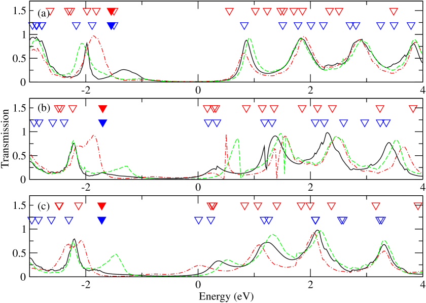
To understand the different electron transport properties for PMPH molecular wire before and after protonation, we plot the transmission curves for PMPH, MP-PMPH, and DP-PMPH at zero bias voltage in Fig. 3. The main common feature of the three transmission curves is that there are four broad peaks above Fermi level up to 4 eV. Below the fermi energy, above -2.5 eV, there are two transmission peaks. The one higher in energy is however very low in transmission. For PMPH, the four above-Fermi-level peaks are almost perfect resonances with transmission possibility close to one. However, for MP-PMPH and DP-PMPH, the first of these four peaks is much low than one. As we can see, the conductance at zero bias voltage is mainly determined by the tail of this peak. We name it peak thereafter. Although the hight of peak is much smaller for MP-PMPH and DP-PMPH than that for PMPH, the Fermi energy is farer away from peak for PMPH. As a result, the conductance of PMPH is smaller than those of MP-PMPH and DP-PMPH. From the transmission curves, we can expect that MP-PMPH and DP-PMPH have similar conductance at zero bias voltage, which is exactly what we observed in Fig. 2.
To consider the finite bias voltage transport and rectification behavior, the voltage response of transmission spectrum should be studied. In Fig. 3, we also plot the transmission curves at a bias voltage of 1.0 V. Because the heights and positions of peak is more strongly affected by the bias voltage in MP-PMPH and DP-PMPH junctions than that in PMPH junction, the latter gives much smaller rectification effect. We notice that for MP-PMPH, there is a sharp transmission peak overlapping with peak at zero bias voltage, and closing to peak at -1.0 bias voltage. At negative bias, this sharp peak even give near perfect transmission, but since the peak is narrow and relatively far away from the Fermi level, it does not really contribute to the low bias conductance of MP-PMPH.
III.3 MPSH orbital analysis
The transmission peaks can be considered as resonant transmission of the electron through renormalized molecule orbitals, which can be obtained by diagonalizing molecular projected self-consistent Hamiltonian (MPSH). Both the energies of orbitals of free molecule (with two thiol groups at two ends) and MPSH orbitals at zero bias voltage are marked by upside-down triangles in Fig. 3. The first row corresponds to molecular orbitals, and the second row is MPSH eigenvalues. By comparing the energies, we notice that almost all transmission peaks are mainly contributed by a MPSH orbital. At the same time, the MPSH orbitals are closely related to molecular orbitals. Typically, we can find a one-to-one map for molecular orbitals and MPSH orbitals by comparing their real space distribution. li0693 ; li0616 ; wu0512 As shown in Fig. 3, their energies are also comparable after a rigid shift. The amount of the rigid energy shift for molecular orbitals is chosen to align an arbitrarily chosen molecular orbital with its corresponding MPSH orbital, as indicated by solid triangles in Fig. 3. There are several reasons why an energy shift is necessary. The real part of the electrode self energy may shift the MPSH energy, and, as suggested by Morales et al., Morales0556 the dipole moment of the molecule may also shift local vacuum level.
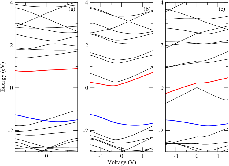
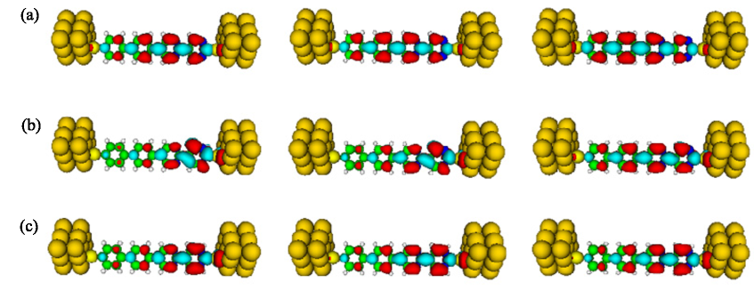
Voltage response of transmission can also be analyzed by MPSH orbitals. Bias voltage may change both the position and the shape of a transmission peak. The peak position generally will follow the energy of corresponding MPSH orbital. In Fig. 4, we plot MPSH energies versus bias voltage, which can also be roughly considered as transmission peak positions versus bias voltage. The line shape and height of transmission peak will be determined by the MPSH orbital real space distribution (transmission channel). Well delocalized transmission channel will give almost perfect transmission (close to one), and strong electrode-molecule coupling results broad transmission peak. For all three junctions studied here, according to the position of the Fermi energy, the low bias transport is mainly determined by peak , the first above-Fermi-level peak. The real space distribution of the corresponding MPSH orbital of peak is plotted in Fig. 5.
For PMPH, peak mainly comes from MPSH LUMO. As shown in Fig. 4 and 5, the energy of MPSH LUMO is only slightly affected by the bias voltage, and the real space distribution is also not very sensitive to bias voltage. As a result, the position of transmission peak is almost independent with the bias voltage, and peak width and height are only slightly changed. For MP-PMPH, the corresponding MPSH orbital is relatively insensitive to negative bias voltage, but become much more symmetric and delocalized at positive bias voltage. Therefore, its peak is much higher at positive bias voltage. However, the MPSH orbital also upshift much at positive bias voltage, which makes peak far from Fermi energy. Finally, we get smaller conductance at positive bias voltage. The sharp peak overlapped with peak at zero bias comes from the next MPSH orbital, which is mainly distributed within bipyrimidinyl group, and thus gives only a low transmission possibility.
It is interesting to note that the transmission response to bias voltage for peak behaviors in the same way for all these three junctions. At negative bias, the peak shift to lower energy, and its magnitude decrease. At positive bias, we get both higher peak position and height. At a first look, it is strange, since the molecules are oppositely polarized. However, if we look at the corresponding MPSH orbitals for peak in Fig. 5, we find that they are all polarized at the same direction. They are all distributed in the dipyrimidinyl group more than in diphenyl group. Of course, the magnitude of polarization is very different. The MPSH orbital for PMPH junction is almost unpolarized, so it is well delocalized within the whole molecule, and gives very high transmission. For MP-PMPH and DP-PMPH, the MPSH orbital is highly polarized even at zero bias, therefore peak is much lower than one, and the peak position is more strongly dependent on the bias voltages. As a result, MP-PMPH and DP-PMPH gives much larger rectification coefficient at small bias voltage. Therefore, to understand the transport properties, we should look into the electronic structure in more details, not only the polarization of the whole molecule, but also the polarization and its voltage response of the relevant orbitals which are close to Fermi level.
IV Effects of molecular anchoring model
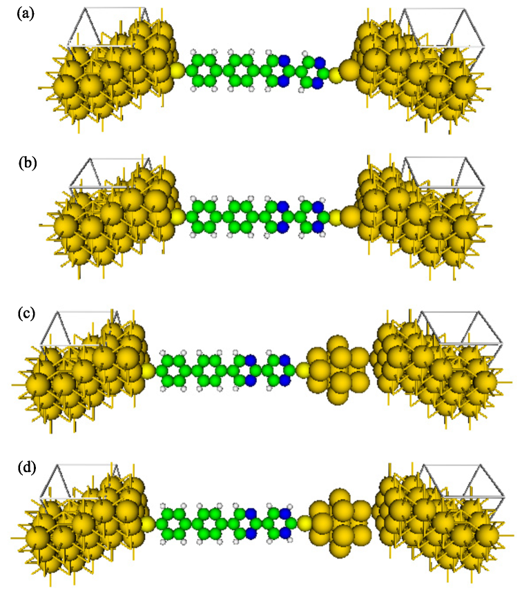
Until now, the thiol anchoring group is connected to gold surface through the fcc hollow site. This is a standard model, but it may not be adequate to describe the experimental setup by Morales et al., Morales0556 where a gold nanoparticle is suspended. The surface of a nanoparticle may be far away from a clean (111) surface. On the other hand, the nanoparticle may address some stress to the diblock molecule, and the electrode-electrode distance may be much different from its equilibrium value. Another big issue is that the STM tip typically is not contact with the Au nanopariticle in STS measurements. Based on these concerns, we construct two more geometrical models for PMPH and DP-PMPH, namely apex model and cluster model. In apex model, we add an apex Au atom on Au (111) surface at the bipyrimidinyl side, and obtain junctions PMPH-A and DP-PMPH-A. In these two junctions, the distance of the two electrode is determined by an optimization with electrode represented by a Au4 cluster. The cluster model is constructed with the diblock molecule connecting to a sphere shaped Au13 cluster, which is separated with the Au(111) surface by 4 Å. The resulted two junctions are called PMPH-C and DP-PMPH-C. The geometrical structures of these four junctions are plotted in Fig. 6.
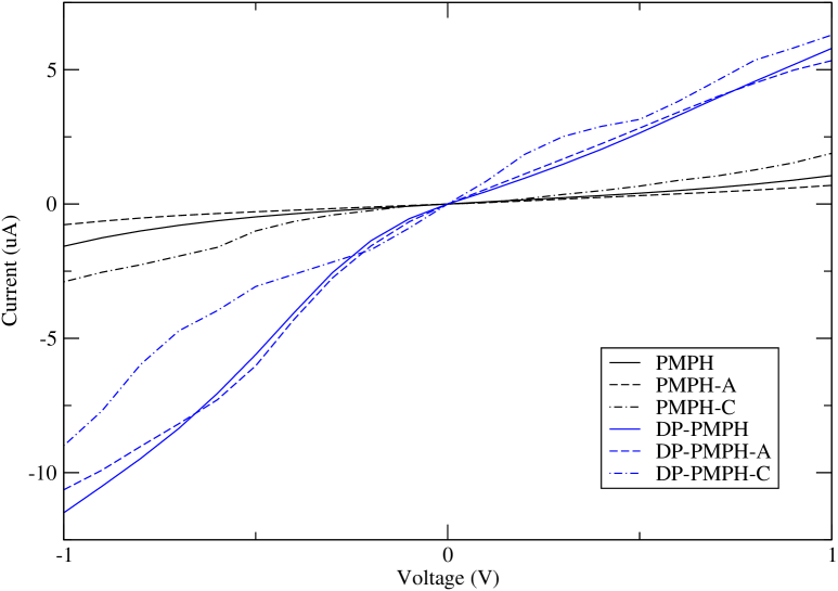
Despite the difference of anchoring geometries, the calculated current-voltage curves, as shown in Fig. 7, however, are qualitatively same for standard, apex, and cluster model. Especially for apex and standard model, the difference of I-V curves is very small. The cluster model gives relatively larger difference, but still no rectification inversion observed. This result indicates that the failure to reproduce of the experimental rectification inversion is not a result of unrealistic anchoring model. It is interesting to notice that, with a 4 Å gap, the current through PMPH-C junction is larger than that through PMPH junction. For DP-PMPH-C, current increases comparing to that of DP-PMPH at positive bias voltages, and decreases at negative bias voltages.
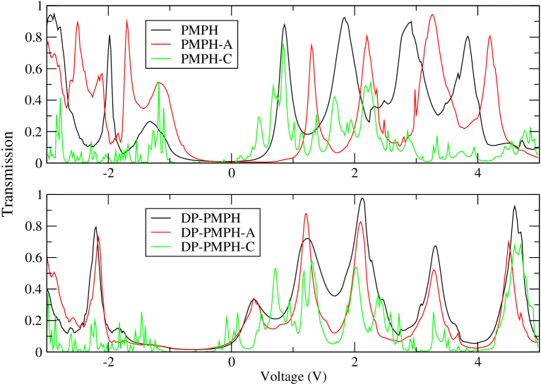
The conductance behavior can be understood from transmission spectra. In Fig. 8, we plot the transmission spectra for these junctions. For apex model, as we expected, the transmission spectra are more or less the same as those for hollow model, except that there is a shift for PMPH-A comparing to PMPH. For cluster model, transmission characters are much more complicated than standard model, because the electronic structure of the gold cluster manifest itself in, as it does in dithiocarboxylate anchoring group.li0616 The interesting conductance enhancement of cluster model comes from some new small peaks very close to Fermi energy. Therefore, for off-resonance transport, it not obvious to get small conductance with weaker electrode-molecule coupling. comment At the same time, the richer transmission feature brought by Au cluster makes the I-V curve less smooth for the cluster model junctions.
V Conclusions
Transport properties of PMPH diblock molecular wire with and without protonation are studied theoretically by combining NEGF and DFT. Protonation is found to be able to enhance conductance and rectification, but no rectifying direction inversion is found in this study. Anchoring geometry effect is carefully checked and it turns out that it is not relevant in this issue. Our calculations indicate that the rectification inversion observed in experiment may not be an intrinsic molecular property related to protonation, and more sophisticated theory should be developed to explain this experiment. There may be two important things missed in this study. One is the interaction between molecular wire and environmental dodecane and solvent molecules, and the other is the electron correlation beyond the NEGF+DFT level of theory.
acknowledgments
The author is grateful to D. S. Kosov for helpful discussion.
References
- (1) A. Aviram and M. A. Ratner, Chem. Phys. Lett. 29, 277 (1974).
- (2) A. Nitzan and M. A. Ratner, Science 300, 1384 (2003).
- (3) C. Joachim and M. A. Ratner, Proc. Natl. Acad. Sci. U.S.A. 102, 8801 (2005).
- (4) R. M. Metzger, Chem. Rev. 103, 3803 (2003).
- (5) G. M. Morales, P. Jiang, S. Yuan, Y. Lee, A. Sanchez, W. You, and L. Yu, J. Am. Chem. Soc. 127, 10456 (2005)
- (6) J. Taylor, M. Brandbyge, and K. Stokbro, Phys. Rev. Lett. 89, 138301 (2002).
- (7) Z. Li and D. S. Kosov, J. Chem. Phys. B 110, 9893 (2006).
- (8) Z. Li and D. S. Kosov, J. Chem. Phys. B 110, 19116 (2006).
- (9) J. M. Soler, E. Artacho, J. Gale, A. Garcia, J. Junquera, P. Ordejon, and D. Sanchez-Portal, J. Phys.: Condens. Matter 14, 2745 (2002).
- (10) N. Troullier and J. L. Martins, Phys. Rev. B 43, 1993 (1991).
- (11) J. P. Perdew and A. Zunger, Phys. Rev. B 23, 5048 (1981).
- (12) M. Brandbyge, J.-L. Mozos, P. Ordejon, J. Taylor, and K. Stokbro, Phys. Rev. B 65, 165401 (2002).
- (13) ATK version 2.0, Atomistix A/S (www.atomistix.com).
- (14) X. Wu, Q. Li, J. Huang, and J. Yang, J. Chem. Phys. 123, 184712 (2005)
- (15) We also want to emphasize that this conductance enhancement of cluster model comparing to standard model may be an artificial result at the NEGF+DFT level of theory, which does not consider electron correlation very well.