Electronic structure and magnetic properties of graphitic ribbons
Abstract
First principles calculations are used to establish that the electronic structure of graphene ribbons with zig-zag edges is unstable with respect to magnetic polarisation of the edge states. The magnetic interaction between edge states is found to be remarkably long ranged and intimately connected to the electronic structure of the ribbon. Various treatments of electronic exchange and correlation are used to examine the sensitivity of this result to details of the electron-electron interactions and the qualitative features are found to be independent of the details of the approximaton. The possibility of other stablisation mechanisms, such as charge ordering and a Peierls distortion, are explicitly considered and found to be unfavourable for ribbons of reasonable width. These results have direct implications for the control of the spin dependent conductance in graphitic nano-ribbons using suitably modulated magnetic fields.
pacs:
pacsI Introduction
Recently, room temperature ferromagnetism has been reported for samples of highly oriented pyrolytic graphite that has been irradiated with high energy protons esquinazi ; esq2 ; esq3 . These observations have fuelled interest in the magnetic properties of carbon-only materials, which are of both great technological and fundamental importance. The experimental evidence gathered thus far indicates that the magnetism does not originate from or electrons provided by chemical impurities but states of - symmetry unpaired at structural defects esquinazi2 . The interest in - magnetism predates these recent discoveries rode ; turek ; sradnov , and so does the interest in the technological exploitation of nanosized particles of graphite, or nanographite, which exhibit unusual features depending on their shape, surface termination and applied field or pressuretoshia . Their tunable and controllable properties open the way to implementing electro-magnetic devices that are simultaneously high-tech, low-cost and easy-to-process.
A graphitic ribbon, created by cutting a graphene sheet along two parallel lines, exhibits edges, which lower the dimensionality of the system and, if close enough to each other, produce a nanosized material. This system is particularly interesting from a theoretical point of view because the investigation of its properties as a function of width allows one to explore nanosize effects as well as bulk effects and the crossover between the two. Moreover, graphitic ribbons are of particular interest from the magnetic point of view as the presence of zig-zag edges disrupts the diamagnetic delocalisation of the graphitic -electron system creating an instability which can be resolved by stabilisation via electronic spin polarisation. Several theoretical studies employing the tight-binding model and density functional theory (DFT) have been devoted to graphitic ribbons fujita ; hikihara ; kusakabe and indicate that both charge localisation and paramagnetism occur in ribbons with zig-zag edges waka . Experimental evidence of a room temperature paramagnetic response exists for activated carbon fibers consisting of disordered networks of minute graphitic fragments about 2-3 nm across enoki .
Room temperature ferromagnetism requires that long range order exists amongst the localised spin moments, of such a strength as to survive significant thermal fluctuations. While the creation of localised magnetic moments in these systems has been widely investigated arcon ; yamashiro , the mechanism, strength and range of the interaction between these moments are still largely unexplored. The current work addresses the strength and range of the magnetic interactions amongst the magnetic centres in graphene ribbons with parallel, zig-zag edges. This is achieved by computing the magnetic interaction strength as a function of the ribbon’s width. The method of choice for this work is hybrid exchange density functional in the B3LYP form. bec88 ; bec93 ; lyp88 The mixing of non-local and semi-local exchange present in hybrid-exchange functionals, overcomes the major flaws of the local density (LDA) and generalised gradient (GGA) approximations in the prediction of the correct electronic and magnetic ground state in strongly correlated electron systems picket89 ; Mackrodt93 . Furthermore, they yield an improved quantitative description of thermochemistry ern99 , optical band gaps mus01 , magnetic moments and coupling constants mar97 ; bre00 ; mor02 ; per01 ; feng_nio_J_04 ; feng_cacuo2_04 and metal insulator transitions feng_nio04 in strongly interacting systems. This approach has also been used succesfully in recent studies of magnetic ordering in wide band gap semiconductors schmidt_mgti2o4_04 , Prussian blue analogs chan2 , and and in fullerene based metal-free systems chan2 ; chan . It appears that the hybrid exchange approach allows the balance between electron localisation and delocalisation, which is crucial in the current work, to be described more reliably than in the LDA and GGA. The authors, however, are not aware of a systematic study of the perfomances of B3LYP for systems containing localised (in the sense of non-bonding/atomic) orbitals of only s-p nature. The sensitivity of the calculated results to the treatment of electronic exchange and correlation is therefore explored by comparison with LSDA and GGA calculations. In addition to the magnetic stabilisation, alternative mechanisms involving geometric distortion and charge polarisation are also addressed.
The organisation of this article is as follows: in section II the details of the system and of the computations are described. In section III, the electronic structure of the non-magnetic state and the eventuality of an instability with respect to the electron-lattice interaction are discussed. In section IV the possible magnetic states (para-, ferro-, and antiferromagnetic) and the strength of the exchange interaction as a function of the ribbon width are investigated. Before concluding in Section VI, section V presents a preliminary study of the likelihood of a charge-polarised state as opposed to the spin-polarised one.
II System’s geometry and computational details
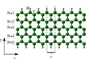
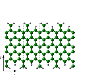
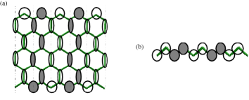
A graphene ribbon of the type shown in Fig. 1 is obtained by cutting a graphene sheet along two parallel zig-zag lines. The ribbon is periodic in the direction only, and the unit cell is delimited by the dashed lines. The width of the ribbon along the non periodic dimension , is defined here by the number, , of trans–polyacetylene-like rows of carbon atoms that run along . Concerning the electronic structure of a ribbon, this work mainly investigates one type of termination for the dangling bonds at the edges: the mono-hydrogenated ribbon (Fig. 1 illustrates this ribbon structure for =5). Concerning the magnetic properties, the study is extended to the cases of non-terminated and methylene group terminated ribbons, the latter being depicted in Fig. 2 (=5), where the dangling bonds are saturated alternatively by a methylene group and a H atom (saturation with methylene groups only in a planar configuration is prohibited by the steric hindrance between adjacent methylene groups). In the monohydrogenated ribbon, the electron states of the edge atoms are bound to appear closer to the Fermi level than the states, since the latter provide a stronger bonding interaction than the former. In the following the focus will be on these highest occupied states.
The first principles calculations presented here have been performed using
the hybrid exchange density functional B3LYP
as implemented in the CRYSTAL package crystal .
In CRYSTAL, the crystalline wavefunctions
are expanded as a linear combination of atom centred Gaussian orbitals
(LCAO) with , , , or symmetry. The calculations reported
here are all-electron, i.e., with no shape approximation to the ionic potential or
electron charge density.
The geometry optimisations are performed
using the alghorithm proposed by Schlegel et al sch82 .
The starting geometry was determined by cutting a sheet of graphene
optimised with B3LYP and saturating the dangling bonds with H atoms,
with a C–H distance equal to that of B3LYP-optimised benzene.
The optimisation with B3LYP for graphene gave a lattice constant value
of 2.460 Å, which is only 0.04% smaller than
the experimental lattice constant of natural graphite
and corresponds to C–C bond lengths of 1.420 Å.
The B3LYP optimised C–H bond length of benzene is 1.093 Å, consistent
with the experimental value of 1.080 Å benzene .
Basis sets of double valence quality (6-21G∗ for C
and 6-31G∗ for H) are used.
A reciprocal space sampling on a Monkhorst-Pack grid of shrinking
factor equal to 60 is adopted after finding it
to be sufficient to converge the total energy to within eV per unit cell.
The Gaussian overlap criteria which control the
truncation of the Coulomb and exchange series in direct space
are set to , and .
Typically linear mixing of 70% and an Anderson second order
mixing scheme is used to guide the
convergence of the SCF procedure.
Level shifting (typically by 0.3 a.u.) is sometimes required
to converge the non-spin polarised configuration.
In order to compare the energies of various magnetically ordered
states, it is necessary to converge stable self-consistent field
solutions for different electronic spin configurations. This is
achieved by preparing a superposition of aligned or antialigned
spin densities for particular atomic states to provide
a suitable initial wavefunction.
It is important to note that that this only affects the initial
wavefunctions and that all solutions presented are unconstrained
and self-consistent.
III Non-magnetic state
III.1 Electronic band structure and density
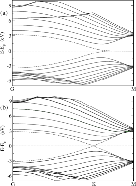
In this section, the properties of the non-magnetic state of a mono-hydrogenated ribbon of width =10 are discussed. Ribbons with the other terminations considered here and of different width show a qualitatively similar behaviour and will therefore not be discussed in detail. Fig. 3 shows the band structure of (a) the ribbon compared to that of (b) an infinite graphene sheet projected onto the ribbon’s first Brillouin zone. In both cases, only the bands due to the pz orbitals are shown because these states, which sandwich the Fermi level, , are the relevant states for this study. The most striking difference between (a) and (b) affects the highest occupied and the lowest unoccupied band, represented with dashed lines. The shape of these two bands in (a) and (b) is similar between and but becomes markedly different between and (). In the case of graphene, (b), the two bands become degenerate at at a single point, which is equivalent to the K point (point at which the semimetallic zero-gap appears) in the first Brillouin zone of graphene, and then diverge from each other between K and . In the case of the ribbon, the two bands converge until they become degenerate exactly at (and the point at which this happens depends on the ribbon’s width) graphband , and they remain degenerate and totally dispersionless until . This results in a high density of states at and this electronic structure suggests an instability that might be resolved by a number of mechanisms including: (i) a geometric distorsion; (ii) electronic spin polarisation; (iii) electronic charge polarisation. The likelyhood of each of these eventualities will be investigated in this work.
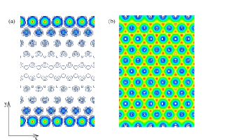
By plotting the electron density from states with an energy falling in a small interval below the Fermi level, the location of the dispersionless states at within the ribbon can be visualised. By choosing an energy interval of 0.4 eV, the charge density map in Fig. 4(a) is obtained. The electron density is localised mostly at the edges, with the peaks corresponding to the location of the C atoms at the edges, and decays into the bulk of the ribbon. In the following, therefore, the two dashed bands will be referred to as the “edge” bands. Notably, due to the topology of the lattice, the atoms of the two edges belong to different sublattices of the bipartite graphene lattice and therefore the degenerate orbitals at EF interpenetrate in a non-bonding network. Within a tight binding model, Fujita et al. fujita have shown that non-bonding orbitals alone form the dispersionless part of these bands. At the states are fully localized at the edges and as approaches they penetrate into the bulk.
In contrast, projection onto the rest of the occupied bands in Fig. 3(a) produces the charge density plot in Fig. 4(b). The electronic charge contributed by these states is distributed across the whole ribbon, and does not decay. The highest values of this density correspond to the positions of the C atoms with the exception of the edge’s atoms and is significant also along the C-C bonds, showing a strong bonding character. These states are in nature the same as the bonding states in graphene and in the following they will be referred to as “bulk” bands.
III.2 Geometric Distortion
As mentioned in the previous section, the high density of states at the Fermi level present in the non-magnetic ribbons may indicate an instability with respect to a geometric distortion, which in this case would be a Peierls distortion as the system is one-dimensionally periodic peierls . The prototype system for a Peierls distortion is trans-polyacetylene which, interestingly, coincides with the =1 mono-hydrogenated ribbon. It is therefore interesting to investigate whether also ribbons with 2 are unstable with respect to dimerisation.
The nature of the electronic states at in polyacetylene, however, is drastically different from those of a ribbon with 2. kertesz By inspection of Fig. 3(a) all “bulk” bands appear to be nearly degenerate at (about 3 eV below the Fermi level). By applying a simple LCAO scheme to a ribbon with one obtains the description displayed in Fig. 5(a), where a wavefunction of those degenerate “bulk” bands is superimposed upon a wavefunction of the two-fold degenerate state at the Fermi level at . Analogously, for the case of undistorted polyacetylene, Fig. 5(b) represents one of the possible wavefunctions of the two-fold degenerate state at . In polyacetylene, the non-bonding orbitals are located on nearest neighbours and thus may gain electronic stabilisation energy by forming dimers with a consequent opening of a gap at the Fermi level. In the ribbon, the same orbitals are separated by sites in which orbitals participate in “bulk” states. In order for the edge states to dimerise the bulk bonding must be disturbed causing an energy loss which competes with the energy gained from dimerisation. The energy cost of dimerisation increases with ribbon thickness and therefore one expects dimerisation to be suppressed at some critical ribbon width. Our fully relaxed, first principles calculations, predict a bond alternation length along the polyacetylene-like chain at the edge is 0.027 Å for N=2 and smaller than 0.001 Å for N=3. The sharp decrease of the magnitude of the dimerisation with N is a measure of the rigidity of the underlying bonding structure.
Full structural relaxation of the =10, mono-hydrogenated ribbon confirms the absence of a dimerisation distortion but at the same time a lattice distortion occurs due to an edge relaxation effect. To describe the topology of the relaxation we adopt the view in which the ribbon is made up of polyacetylene-like chains linked by rungs. A carbon atom in the bulk has two intrachain bonds and one interchain (rung) bond with its nearest neighbours; at the edge only intrachain bonds are present. The edge relaxation consists of a uniform contraction (by 0.02 Å in the case of =10) of the intrachain bonds at the edge and a consequent expansion of the interchain rungs. This effect decrease sharply moving away from the edge and is to be ascribed to the accumulation of extra bonding charge (with respect to the bulk bonds) at the non-bonding part of the orbital at the edge. Contrary to the Peierls distortion in polyacetylene, not all the non-bonding charge at the edge participates in this extra bonding due to the lack of a bonding counterpart at the atom involved in an interchain bond. Crucially this establishes that the localised non-bonding charge persists at the edge even after surface relaxation, mantaining its tendency towards a magnetic state, as it will be shown in section IV.
III.3 Very wide ribbons and the graphene limit
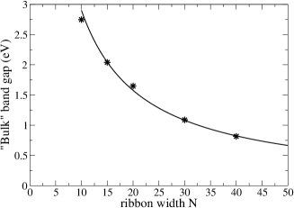
As the width of the ribbon increases, it is expected that its “bulk” bands, as defined in Sec. III.1, will recover the graphene limit and the gap between the “bulk” occupied and “bulk” unoccupied states will eventually close. In other words, for , the band structure of a ribbon will be given by the superposition of the graphene band structure and the two “edge” bands which, sandwiched between the bulk bands, will become degenerate,with an energy equal to , at (K). It is therefore interesting to determine the ribbon’s width at which the band gap between the “bulk” states in a ribbon closes. By extrapolating the data in Fig. 6, this gap is found to recover the graphite limit of a zero band gap, within the room temperature thermal energy, when the ribbon width is . This result is independent of whether the geometry of the ribbons is constrained at the graphene geometry or fully relaxed. This critical width is very large, indicating that the screening of the perturbation caused by the presence of the edges is very slow compared to, for instance, the screening of an electronic perturbation at the surface of semiconducting crystals (typically around 10 nm). The much larger penetration depth in graphitic ribbons could be related to the large delocalization energy (hopping parameter t 2.5 eV) typical of carbon aromatic systems, as well as to their dimensionality. Unusually long ranged surface effects have been found in previous studies of graphitic systems. In a combined AFM/STM study, Ruffieux et al. observed electronic polarisation effects extending over a range of 5060 nm when H was adsorbed on graphite ruffieux . In a diamagnetic susceptibility study, waka it was found that the the slope of the orbital susceptibility as a function of the ribbon width depends on whether it has a zig-zag or armchair geometry. Surprisingly, the difference between the slope in the two cases was observed to increase with the ribbon’s width.
The long-ranged nature of these effects indicates that in the graphene ribbon a small concentration of defects would be enough to drastically alter the semimetallicity and the conducting properties of the material. This conclusion may also be tentatively extended to a wide range of graphitic systems but the effects of the three dimensional structure requires further investigation.
IV Electronic Spin Polarisation
IV.1 Electronic band structure and density of states
As the analysis in Sec. III.2 excludes the possibility that a Peierls distortion can resolve the instability brought about by the high density of states at the Fermi level in the non-magnetic ribbons, the eventuality of stabilization through spin polarisation is investigated here.
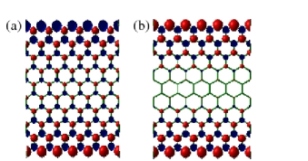
By allowing the system to be spin-polarised, stable magnetic states are found, whose spin density is shown in Fig. 7(a) and Fig. 7(b). Here, the state depicted in Fig. 7(a) is referred to as antiferromagnetic (AF) because the spin moments on the C atoms on one edge are anti-aligned to the spin moments on the opposite edge. Fig. 7(b) shows the ferromagnetic (FM) configuration, where the spin moments on both edges point in the same direction.
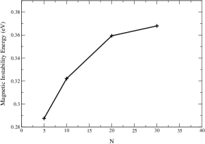
Both the AF and FM configurations are found to have a total energy lower than the non-magnetic state for all ribbon widths, indicating that spin polarisation is a possible stabilisation mechanism. The energy difference between the non-magnetic and the antiferromagnetic states plotted in Fig. 8 is a measure of the strength of the magnetic instability. The stabilisation is larger for wider ribbons and converges to about 0.38 eV per unit cell at . Unlike the idealised system presented here, however, realistic systems are likely to present a mixture of zig-zag and armchair edges. Since the armchair edges do not give rise to a high density of states at the Fermi leveldresselhaus , the magnetic instability computed here for the idealised system is likely to be overestimated with respect to the systems experimentally realised thus far.
The ground state of the system is found to be the AF case, as predicted by the spin alternation rule discussed elsewhere chan and formally expressed in Lieb’s theorem lieb in the framework of a Hubbard model. It is noteworthy that the spin alternation rule is satisfied also at the DFT level, which goes beyond the strictly on-site treatment of the electron-electron interaction of the Hubbard model. These results, therefore, extend the validity of the spin alternation rule beyond the approximations of the Hubbard model.
The analysis of the electronic structure and energetics of these two stable magnetic states as a function of the ribbon’s width documents the range of the magnetic interaction between the edges and the nature of the stabilisation mechanism via spin polarisation. In Fig. 9 the band structures of the AF (upper panel) and FM (lower panel) states are presented. The instability of the non-magnetic case discussed in Sec. III.1 is resolved into two completely different but well-known scenarios: the AF solution gives a Slater insulator, whilst the FM solution gives a Stoner metal.
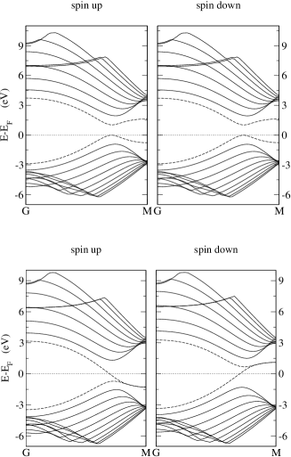
In the AF configuration, opposite spin polarisation on neighboring sites localises the electrons in singlet pairing between the two sublattices and a band gap opens at , where the valence and conduction bands of graphene are degenerate (Fig. 3). The electronic ground state of a mono-hydrogenated ribbon of finite width is therefore insulating. As the width increases, the band gap tends to zero following an algebraic decay of the type 1/N (as for the “bulk” gap of Fig. 6). The band gap vanishes, within the room temperature thermal energy, when N400, i.e., for a 80 nm width. This length scale could be reached by the nanotechonolgy industry in the future with the synthesis of single, relatively thin sheets of nanographite.
Conversely, in the case of the metastable FM configuration the spin-up and spin-down bands cross in a non-bonding fashion at at . The states near are delocalised in the middle of the ribbon, where no spin density is present. In contrast, a small amount of spin polarisation and electron localisation is present in the same region in the case of the AF configuration, indicating that the spin polarised nature of its “edge” states penetrates deeper into the bulk. The range of “edge” states and of the magnetic interactions will be discussed further in Sec. IV.2. Notably, no significant difference is detected in the “bulk” bands of the non-magnetic, AF and FM cases, indicating that magnetic effects on these bands are negligible. As the ribbon’s width increases, the “bulk” bands closest to approach each other and eventually become degenerate at , thus recovering the graphene band structure.
From a nanotechnological point of view, the AF and FM band structures show some appealing features. In fact, the prediction that at the nanometer level an AF allignment of the edges’ spins produces a strongly insulating state and that a FM alignment is conducting, implies that one is able to control the conducting properties of a nano-sample by applying appropriately modulated magnetic fields.
By adopting a mean-field version of the Hubbard model with nearest neighbour hopping, it is possible to estimate the values of the hopping integral, , and of the on-site Coulomb repulsion parameter, usually referred to as the Hubbard . This is achieved by fitting the computed band structure due to the “edge” states at with that produced by the Hubbard model. The resulting values are: eV and . Note that this Hubbard parameter, defined as the direct Coulomb integral between the non-bonding localised orbitals (of atomic nature, as for the -orbitals in transition metal compounds) that exist at the edges of graphene ribbons is not to be compared with the parameter of an infinite graphene sheet where the orbitals are always delocalised.
It is noteworthy that the values obtained for and depend on the choice of the exchange-correlation functional used within the DFT calculations. Within the gradient-corrected functional PBE pbe one obtains eV and , while the local density approximation (LSDA) vbh gives =2.5 eV and .
These trends can be understood in terms of the approximation to the electronic exchange in the various functionals. The LSDA has a tendency to delocalise states and suffers from electron self-interaction which, in this context, results in a lower value for the Hubbard U parameter. The LSDA might therefore be expected to yield an overestimation of the hopping parameter and an underestimation of U. The gradient-corrected PBE functional contains a somewhat better description of the semilocal exchange which increases U but does not significantly affect . The B3LYP functional contains an element of Fock exchange which explicity compensates for electronic self-interaction and therefore provides a significantly higher U, and tends to localise the electronic states much more than LSDA or GGA. As will be discussed in the next section, a higher degree of delocalisation increases the strength of the magnetic interaction but decreases its range. As discussed above, B3LYP is likely to provide a more reliable description of this delicate balance but further studies of - bonded systems are required to establish this.
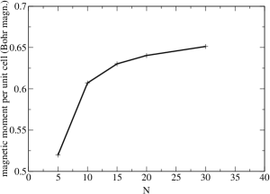
Fig. 10 shows the magnetic moment per unit cell for the FM case which, as expected, approaches the saturation value of 2/3 . As the ribbon widens, the covalent interaction between the tails of the edges’ wavefunctions diminishes in favor of a purely ionic arrangement of the charge which consists in 1/3 (for each edge atom) not participating in any bonding.
IV.2 Range of magnetic interaction
As the AF and FM states differ by flipping the spin moments of one edge, the range of the magnetic interaction in the ribbons can be measured by computing how the energy difference, , between these two states varies as a function of the ribbon’s width. The behaviour of the B3LYP-computed as a function of the ribbon’s width is plotted in Fig. 11 for the different types of termination described in Sec. II. The plot refers to unrelaxed ribbons (geometric relaxation has been found to affect only negligibly).

By fitting the energy variation with N, one obtains a decay law close to for each of the three different terminations considered here: the mono-hydrogenated, the methylene-group terminated and the non terminated ribbons. This establishes that the essential behaviour in these systems is independent of the particular mechanism used to terminate the zig-zag ribbon edge.
Irrespective of the termination type, a width of , corresponding to approximately 14-16 Å, gives 25 meV and thus room temperature magnetic ordering. This value is significantly higher compared to previous studies based on standard DFT. In a recent LSDA study by Lee et al. lee , the exchange interaction is reported to be less than 5 meV at . Moreover, Wakabayashi et al.waka_03 found a value smaller than 5 meV for in their investigation of the spin wave spectrum within the random phase approximation of the Hubbard model.
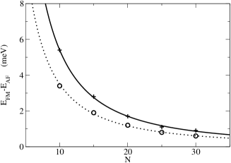
Fig. 12 displays the same property computed for the mono-hydrogenated ribbons within the GGA functional PBE and the LSDA. As noted in Sec. IV.1, when calculating the Hubbard U the degree of charge localisation is smaller in PBE and LSDA than in B3LYP; the magnetic tails of the edge states in PBE and LSDA are more delocalised and therefore more long-ranged. The delocalisation of the state means that the strength of the interaction is lower than with B3LYP but its range is increased. The decay power law is within PBE and within LSDA. It is interesting to note that only very narrow ribbons could display room temperature magnetic order according to LSDA and GGA, whilst within B3LYP their width is predicted to extend to 1-2 nm.
V Electronic Charge Polarisation
The instability brought about by the
high density of states at the Fermi level in the non-magnetic
ribbons could, in principle, also be resolved by a charge polarisation mechanism.
When the Hubbard model is extended to include off-site
Coulomb interactions, for instance, the possibility of charge order appears.
Recently, Yamashiro et al.
investigated the effect of nearest-neighbour interactions for a graphitic ribbon
adopting an extended Hubbard model
within the unrestricted Hartree-Fock (UHF) approximation.
In their study it was found that
for some values of the off-site parameter, the charge-polarised (CP)
and spin polarised states compete.
The possibility of a CP state is explored here for an ribbon and
within two levels of theory: UHF and B3LYP.
In the case of UHF, a metastable CP state can be computed in which a
charge transfer of about 0.05
occurs from the C atoms of one edge
to those of the other.
The spin-polarised state, however, is much more stable (by 1 eV per cell) than
the CP state.
In the case of B3LYP, different initial charge densities were tried,
corresponding to charge transfers of 0.05 (as in the stable UHF
solution) and 0.04 . All such states, however, converge to the spin-polarised
solution. If the proportion of Fock exchange included in the hybrid functional
is increased from 20% (i.e. the percentage of Fock exchange present
in B3LYP),
a metastable CP state is only achieved at the extreme limit
of 100% which corresponds to UHF with a LYP treatment of correlation.
It seems that this extreme limit produces an unphysical instabilty and indeed
it is found that both the 100 Fock exchange functional and UHF theory
predict the FM state to be the ground state for larger ribbon widths
which is inconsistent with all other
results and clashes with Lieb’s theorem and the spin alternation rule.
VI Discussion and Conclusion
In this work, the possible stabilisation mechanisms for a zig-zag ribbon via geometric distortion, spin polarisation and charge polarisation have been investigated. The influence of the ribbon’s width on the electronic structure and relative stability of the different solutions were also analysed.
The topology of the non-bonding crystalline orbitals at the edges does not allow for a significant Peierls distortion for ribbons with N greater than 3 but rather an edge relaxation which preserves a strong tendency of the system to stabilise through a magnetic polarisation, where magnetic moments are localised at the edges. Two magnetic states were investigated: (i) an antiferromagnetic configuration where the spin moments on the C atoms at one edge are antialigned to those on the other edge; (ii) a ferromagnetic configuration where all spin moments on the C atoms at the edges point in the same direction. Both states were found to be lower in energy than the non-magnetic state for any width of the ribbons. The antiferromagnetic state was found to be the ground state in agreement with the spin alternation rule and extending Lieb’s theorem beyond the nearest neighbour approximation.
The magnetic state was found to be about 0.38 eV per unit cell more stable than the diamagnetic one for wide ribbons. In ribbons that have been realised thus far there is a mixture of zig-zag and magnetically inactive edges which weaken the tendency towards a magnetic state. This is a possible explanation of the recent scanning tunneling spectroscopy experiment in which Niimi et al. niimi measured a peak in the local density of states (LDOS) of edge atoms signalling the existence of a non-magnetic metallic state (Fig 3). In fact, if the system were magnetic, the LDOS at the edge would have shown two symmetric peaks around the Fermi level representing the opening of a Hubbard gap due to the magnetic polarisation of the system, as discussed in session IV.
By fitting the antiferromagnetic band structure to a nearest neighbour Hubbard model the value of the parameter associated with the localised states at the edges was found to be dependent on the exchange-correlation functional used. Going from GGA and LSDA to B3LYP the value increases due to the explicit inclusion of a self-interaction correcting term in the DFT Hamiltonian. The self-interaction error is known to be the main cause of the failure of the LSDA and GGA in the treatment of systems containing localised -orbitals. However it is not clear at present which treatment of exchange and correlation provides the most reliable approach for a system containing localised/atomic-like orbitals.
The magnetic interaction strength was computed as a function of the ribbon width and, within the B3LYP functional, it was found that ribbons less than 1.5-2 nm across retain magnetic order above room temperature. Within LSDA and GGA the magnetic interaction strength is weaker but longer ranged. These three functionals provide differing descriptions of the interplay between localisation and delocalisation and its effect on the strength and range of the magnetic interaction. This is evident in the predicted critical ribbon width at which the magnetic state becomes thermally unstable at room temperature; B3LYP predicts a critical width of 1-2 nm while LSDA and GGA predict a width an order of magnitude smaller.
In conclusion, first principles calculations have been used to establish that the electronic structure of graphene ribbons with zig-zag edges is unstable with respect to a magnetic polarisation of the edge states. This mechanism is stable with respect to alternative stablisation routes involving charge polarisation or structural distortions. The magnetic interaction of the edge states is remarkably long ranged. A band gap in the bulk of the ribbon exists in the antiferromagnetically alligned ground state with the size of the gap also displaying a very long ranged dependence on the ribbon width closing, at room room temperature for ribbon widths exceeding 80nm. The qualitative features of these results are robust with respect to differing treatments of electronic exchange and correlation. This explicit demonstration of the long ranged nature of the magnetic interaction mediated by the delocalised orbitals in graphitic systems is consistent with recent observations of magnetism induced by low defect concentrations in a number of materials. These results have direct implications for the control of the spin dependent conductance in graphitic nano-ribbons using suitably modulated magnetic fields.
Acknowledgments
This work is supported by the European Union under the NEST FERROCARBON project (CEC 012881). The authors would like to thank S. Bennington and T. E. Weller for illuminating discussions and the Computational Science and Engineering Department of the CCLRC for providing the computing facilities.
References
- (1) P. Esquinazi, D. Spemann, R. Höhne, A. Setzer, K.-H. Han and T. Butz, Phys. Rev. Lett. 91, 227201 (2003).
- (2) J. Barzola-Quiquia, S. Petriconi, P. Esquinazi, M. Rothermel, D. Spemann, A. Setzer, T. Butz, cond-mat/0610293.
- (3) H. Ohldag, T. Tyliszczak, R. Hoehne, D. Spemann, P. Esquinazi, M. Ungureanu, T. Butz, cond-mat/0609478.
- (4) T. Butz, D. Spemann, K.H. Han, R. Hohne, A. Setzer and P. Esquinazi, Hyper. Inter. 160, 27 2005.
- (5) A. V. Rode, E. G. Gamaly, A. G. Christy, J. G. Fitz Gerald, S. T. Hyde, R. G. Elliman, B. Luther-Davies, A. I. Veinger, J. Androulakis, and J. Giapintzakis, Phys. Rev. B. 70, 054407 (1999).
- (6) P. Turek, K. Nozawa, D. Shiomi, K. Awaga, T. Inabe, Y. Maruyama,and M. Kinoshita, Chem. Phys. Lett. 180, 327 (1991).
- (7) V. I. Srdanov, G. D. Stucky, E. Lippmaa, and G. Engelhardt, Phys. Rev. Lett. 80, 2449 (1998).
- (8) T. Enoki and Y. Kobayashi, Journ. Mat. Chem. 15, 3999 (2005).
- (9) M. Fujita, K. Wakabayashi, K. Nakada and K. Kusakabe, J. Phys. Soc.Jap. 65, 1920 (1996).
- (10) T. Hikihara,X. Hu, H.-H. Lin, and C. Y. Mou, Phys. Rev. B. 68, 035432 (2003).
- (11) K. Kusakabe and M. Maruyama, Phys. Rev. B. 67, 092406 (2003).
- (12) K. Wakabayashi, M. Fujita, H. Ajiki, and M. Sigrist, Phys. Rev. B. 59, 8271 (1999).
- (13) Y. Shibayama, H. Sato, and T. Enoki and M. Endo, Phys. Rev. Lett. 84, 1744 (2000).
- (14) D. Arcon et al., preprint
- (15) A. Yamashiro, Y. Shimoi, K. Harigaya, and K. Wakabayashi, Phys. Rev. B. 68, 193410 (1999).
- (16) A. D. Becke, Phys. Rev. A 38, 3098 (1988).
- (17) A. D. Becke, J. Chem. Phys. 98, 5648 (1993).
- (18) C. Lee, W. Yang, and R. G. Parr, Phys. Rev B 37, 785 (1988).
- (19) W. E. Pickett, Rev. Mod. Phys. 61, 433 (1989).
- (20) W. C. Mackrodt, N. M. Harrison, V. R. Saunders, N. L. Allan, M. D. Towler, E. Apra, and R. Dovesi, Phil. Mag. A 68, 653 (1993).
- (21) M. Ernzerhof, and G. E. Scuseria, J. Chem. Phys. 110, 5029 (1999).
- (22) J. Muscat, A. Wander, and N. M. Harrison, Chem. Phys. Lett 342, 397 (2001).
- (23) R. L. Martin, and F. Illas, Phys. Rev. Lett. 79, 1539 (1997).
- (24) T. Bredow, A. R. Gerson, Phys. Rev. B 61, 5194 (2000).
- (25) I. P. R. Moreira, F. Illas, R. L. Martin, Phys. Rev. B 65, 155102 (2002).
- (26) J. K. Perry, J. Tahir-Kelhi, WilliamA. Goddard III, Phys. Rev. B 63, 144510 (2001).
- (27) X. Feng and N.M.Harrison, Phys. Rev. B 70, 092402 (2004).
- (28) X.-B. Feng and N.M.Harrison, Phys. Rev. B 69, 132502 (2004).
- (29) X.-B. Feng and N.M.Harrison, Phys. Rev. B 69, 035114 (2004).
- (30) M. Schmidt, W. II Ratcliff, P. G. Radaelli, K. Refson, N. M. Harrison and S. W. Cheong ,Phys. Rev. Lett. 92, 056402 (2004).
- (31) J. A. Chan, B. Montanari, W. L. Chan and N. M. Harrison, Mol. Phys. 103, 2573 (2005).
- (32) J. A. Chan, B. Montanari, J. D. Gale, S. M. Bennington, J. W. Taylor, and N. M. Harrison Phys. Rev. B 70, 041403(R) (2004).
- (33) Saunders, V. R., Dovesi, R., Roetti, C., Orlando, R., Zicovich-Wilson, C. M., Harrison, N. M., Doll, K., Civalleri, B., Bush, I. J., D’Arco, Ph., and Llunell, M. CRYSTAL2003 User’s Manual, (University of Torino, Torino, 2003).
- (34) Schelegel, H. B., 1982, J. Comp. Chem., 3, 214.
- (35) J. Demaison and G. Wlodarczak, Structural Chemistry 5, 57 (1994).
- (36) P. R. Wallace, Phys. Rev. 71, 622 (1947).
- (37) R. E. Peierls, Quntum Theory of solids (Clarendon, Oxford, 1955).
- (38) M. Kertesz and R. Hoffmann, Solid State Comm. 47, 97 (1983).
- (39) P. Ruffieux, O. Groning, P. Schwaller, L. Schlapbach, and P. Groning, Phys. Rev. Lett. 84, 4910 (2000).
- (40) K. Nakada, M. Fujita, G. Dresselhaus and M. S. Dresselhaus, Phys. Rev. B. 54, 17954 (1996).
- (41) E. H. Lieb, Phys. Rev. Lett. 62, 1201 (1989).
- (42) J. P. Perdew, K. Burke, and M. Ernzerhof, Phys. Rev. Lett. 77, 3865 (1996).
- (43) U. von Barth and L. Hedin, J. Phys. C: Solid State Phys. 5, 1629 (1972).
- (44) H. Lee, Y.Son, N. Park, S. Han, and J. Yu, Phys. Rev. B 72, 174431 (2005).
- (45) K. Wakabayashi, M. Sigrist and M. Fujita, J. Phys. Soc. Jpn. 67, 2089 (1997).
- (46) Y. Niimi, T. Matsui, H. Kambara, K. Tagami, M. Tsukada, and H. Fukuyama, Phys. Rev. B 73, 085421 (2006).