Hybrid reciprocal space for X-ray diffraction in epitaxic layers
Abstract
Even after several decades of systematic usage of X-ray diffraction as one of the major analytical tool for epitaxic layers, the vision of the reciprocal space of these materials is still a simple superposition of two reciprocal lattices, one from the substrate and another from the layer. In this work, the general theory accounting for hybrid reflections in the reciprocal space of layer/substrate systems is presented. It allows insight into the non-trivial geometry of such reciprocal space as well as into many of its interesting properties. Such properties can be further exploited even on conventional-source X-ray diffractometers, leading to alternative, very detailed, and comprehensive analysis of such materials.
I Introduction
The capability of growing thin layers of single-crystals onto one face of another single crystal has made possible many fundamental achievements in semiconductor technology. Epitaxic growth is today one of the most important and basic processes used in manufacturing nanostructured devices. Multilayered materials, such as superlattices and quantum wells, or even quantum wires and dots, require epitaxy at some stage of their preparation procedures. X-ray diffraction has been the primary tool for structural analysis of epitaxic layers, with the associated techniques and machinery following closely the needs of the semiconductor industry.
A quarter of a century ago, when using a divergent X-ray source and photographic films to record the layer/substrate diffraction lines [the simplest possible setup (Chang, 1980) to measure lattice mismatch of epilayers], Isherwood et al. (1981) reported the observation of extra features, a kind of short line, appearing all over the recorded images. Such features were sequences of consecutive Bragg reflections in both single-crystal lattices, and were named hybrid reflections. Latter, the phenomenon was quantitatively described and methods to exploit its properties were suggested (Morelhão & Cardoso, 1991; 1993a; 1993b). However, to probe the excitement conditions of hybrid reflections precisely, collimated X-ray beam setups would be necessary, such as those commonly found in most synchrotron facilities where the beam can be highly collimated in two orthogonal directions (Morelhão et al., 1991, 1998, 2002, 2003). Such requirements have created a huge barrier for the systematic usage of this peculiar phenomenon in the technology of semiconductor devices.
Even after several decades of using X-ray diffraction as one of the major analytical tools for epitaxic layers, the vision of the reciprocal space of these materials is still a simple superposition of two reciprocal lattices: one from the epilayer and the other from the substrate. Diffraction conditions generating any other extra feature have been avoided since they could not be explained within this simplistic vision of the reciprocal space. The incident-beam optics available for conventional X-ray sources have, in the past, seemed inappropriate (considering the requirement for a highly collimated beam in two orthogonal directions) to investigate azimuthal-dependet features; consequently, the analysis of epilayers by standard X-ray diffraction techniques would be compromised when hybrid reflections are excited. This work is an attempt to change this scenario. Introducing a reciprocal-space description of hybrid reflections opens the possibility of exploiting in detail the properties of this phenomenon without the necessity of using synchrotron facilities. In other words, instead of avoiding hybrid features when using tube-source diffractometers, exciting them via standard reciprocal-space probing techniques can lead to alternative methods for analyzing epilayered materials. Here, besides presenting the theory and discussing some properties of the hybrid reciprocal lattice, experimental examples are given regarding the type of information that can be accessed by analyzing the phenomenon properly on commercial diffractometers.
II Hybrid reciprocal lattice theory
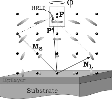
Any three-dimensional reciprocal lattice gives rise to a phenomenon known as -beam diffraction (Colella, 1974; Chang, 1984; Weckert & Hümmer, 1997). Although it can change the relative strength of Bragg reflections, no extra features are generated in the reciprocal space since sums of diffraction vectors always end up at a reciprocal-lattice point (RLP). On the other hand, when two distinct reciprocal lattices are superposed, as in epilayer/substrate systems, sum of diffraction vectors may end up at an empty position of the reciprocal space. This occurs when one diffraction vector in the sum does not belong to the same lattice as the others. In this case, hybrid reciprocal-lattice points (HRLPs) are generated, as illustrated in Fig. 1 and described mathematically below.
Three-beam X-ray diffractions in single crystals are excited when the incident beam (wavevector and wavelength ), fulfills two Bragg conditions:
| (1) | |||||
| (2) |
Since , we also have
| (3) |
where , , and are diffraction vectors of the primary, secondary and coupling reflections, respectively. The primary reflection is the one whose intensity is been monitored while the secondary reflection is brought to diffraction condition by the crystal azimuthal rotation around , as in X-ray Renninger scanning (Renninger, 1937). Other cases of -beam diffractions with will be treated here as coincidental three-beam diffractions.
Only equations (1) and (2) are in fact necessary to predict three-beam diffractions in a single lattice (Cole et al., 1962; Caticha, 1969), which can be either the epilayer or the substrate one. However, there are several other similar diffraction processes: the above-mentioned hybrid reflections, whose secondary and coupling reflections do not belong to the same lattice. To predict what should be the exact incident-beam direction for exciting one of such inter-lattice rescattering process, equations (2) and (3) are more suitable to this purpose, as demonstrated elsewhere for the case of satellite reflections (Morelhão et al., 2003) and summarized here in Appendix A for the case of epilayer/substrate systems. Accounting for all possible rescatterings leads to a reciprocal space that is highly populated with HRLPs and much more complex than that obtained by just superposing both epilayer and substrate reciprocal lattices. This hybrid reciprocal space has been neglected; its features remain unexplored; all knowledge on this matter is found in reports of a few accidental observations (Hayashi et al. 1997, Domagala et al., 2006) sometimes investigated (Morelhão et al., 2003), but most of the time avoided in order not to compromise the system characterization by standard diffraction techniques, such as rocking curves and reciprocal-space mapping in triple-axis goniometry.
To visualize the hybrid reciprocal space, let us label the diffraction vectors of both lattices as
where and subscripts stand for the substrate and epilayer reciprocal-lattice vectors, respectively. , , and are the Miller indexes of the secondary reflection, and the complete hybrid reciprocal space around one chosen primary reflection of the substrate lattice, whose diffraction vector is , only appears by rotating the sample around by . The position of all features regarding the vector is then given by
| (4) |
which is a sub-reciprocal-lattice of points with periodicity , for = , , and , since , , and are integer numbers. They stand for either coupling-reflection () or secondary-reflection () indexes according to or , respectively.
Although equation (4) gives the general aspect of the hybrid reciprocal lattice, there are a few restrictions that should be considered for each particular system. One is the direction of the secondary beam (wavevector ) that must cross the epilayer/substrate interface in order for its respective hybrid diffraction vector, , to be measurable. In other words, if is the interface normal direction pointing upwards into the epilayer and , we have that
| (5) |
Hence are the indexes of the Bragg reflection that occurs in the epilayer lattice. Refraction and total reflection of the secondary beam, , at the interface is also a possibility to be taken into account mainly when . In general, epilayers of quaternary alloys grown on miscut substrates present a relative tilt between both lattices, and this tilt must be considered when calculating .
II.1 Properties of the hybrid reciprocal lattice
One of the most interesting properties of the hybrid reciprocal lattice is that the relative positions of the HRLPs depend exclusively on the lattice mismatch between both real lattices, i.e. their positions do not depend on the X-ray wavelength. What change with is the azimuthal angle, , where each HRLP is excited, as can be calculated by solving equations (2) and (3); see Appendix A. This implies that HRLPs are more easily excited with an X-ray beam that is poorly collimated in the axial direction, i.e. the direction perpendicular to the primary incidence plane: the plane that contains the substrate vector , the X-ray source and the detector system. In commercial high-resolution diffractometers, the beam is highly conditioned in the incidence plane to about a few arc seconds, while the axial divergence is of the order of a few degrees (). On the other hand, in synchrotron facilities for X-ray diffraction, where the beam is well conditioned in both directions, the azimuthal positioning of the sample has to be more accurate if hybrid features are to be measured (Morelhão et al., 2002; 2003).
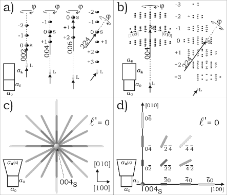
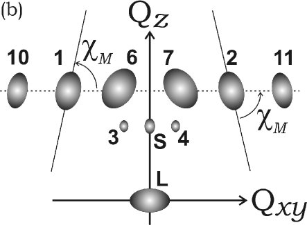
In Fig. 2, the general properties of hybrid reciprocal lattices are depicted. Just a few points aligned along the growth direction in the case of fully strained layers (Fig. 2a), or a well defined three-dimensional lattice of points around the substrate reciprocal-lattice points occurs in the case of relaxed layers (Fig. 2b). Consequently, strain gradients along the layer thickness give rise to a hybrid lattice of rods instead of points, as illustrated in Figs. 2(c) and 2(d). Besides the fact that HRLPs are excited only at certain azimuthal positions, their experimental observation via conventional reciprocal-space mapping techniques also require detection optics with some angular acceptance in the axial direction. When a given HRLP is excited, its diffraction vector is not on the primary incidence plane and neither is its diffracted beam . Therefore, visible HRLPs are those whose diffracted beam, , falls within the angular range of axial acceptance of the detection system. Moreover, HRLP positions on reciprocal-space maps correspond to projections of on the incidence plane. In terms of longitudinal and transversal components of the maps, and respectively, the HRLPs are seen at
| (6) |
where and . It is then possible to calculate
| (7) |
as the takeoff angle of from the incidence plane of the primary reflection. , and is the azimuthal position of around with respect to the same reference direction for and in the same sense of rotation.
II.1.1 Strain grading
A unique property of hybrid reflections arises from the layer reflections since they are always Laue reflections, i.e. transmitted-diffracted beams where diffraction occurs through the entire layer thickness. In any other X-ray diffraction technique, structural analyses of layers are carried out by means of Bragg reflections: those with reflected-diffracted beams. Therefore, in principle, HRLPs are equally sensitive to lattice mismatch at both the top and the bottom of the epilayer. Hence, strain variation across the layer thickness should generate elongated HRLPs, i.e. HRL rods, oriented at specific directions on reciprocal-space maps. Except for the particular cases discussed in Figs. 2(c) and 2(d), which are sensitive only to the in-plane strain grading, the general orientations of the rods are affected by the elastic properties of the layer compound; for example, in the case of (001) growth on cubic systems with parallel, , and perpendicular, , strain gradings. The HRL rod around a symmetric primary reflection will be oriented at an angle where
| (8) |
assuming a tetragonal distortion of the layer unit cell varying as a function of the strain according to and ; is the unstressed layer lattice parameter and, for isotropic materials,
| (9) |
where is the Poisson ratio. Being able to predict HRL rod orientation due to grading is important since there are other causes for the elongated shapes of the HRLPs, as better explained below.
II.1.2 Anisotropic mosaicity
Besides strain grading and finite layer thickness effects, the HRLPs may also present elliptical shapes due to mosaicity in the epilayer. Most diffraction vectors taking part in hybrid reflections have both in-plane and out-plane components, and therefore, they are sensitive to the spatial misorientation of the crystallites, or mosaic blocks, building up the epilayer. In-plane rotation of the crystallites around the growth direction gives raise to a mosaicity of width , while crystallite rotations around in-plane axes give rise to an out-plane mosaic width . It is possible to compute effects of mosaicity on the shape and orientation of the HRLPs by projecting the trajectory of the reciprocal vector
| (10) |
on the incidence plane of the reciprocal-space maps as varies through . and is the layer diffraction vector in , i.e. either or . The orientation angle is with respect to the direction of largest projection so that
| (11) |
when the value of is a maximum.
| HRLP | (Å-1) | () | ||||||||
|---|---|---|---|---|---|---|---|---|---|---|
| 1 | 27.7043 | 27.6 | ||||||||
| 2 | 27.8258 | 27.6 | ||||||||
| 3 | 28.5022 | 27.6 | ||||||||
| 4 | 28.5928 | 27.6 | ||||||||
| 5 | — | 28.5865 | 27.6 | — | — | — | — | |||
| 6 | 30.1328 | 30.0 | ||||||||
| 7 | 30.0750 | 30.0 | ||||||||
| 8 | — | 30.0369 | 30.0 | — | — | — | — | |||
| 9 | — | 29.8584 | 30.0 | — | — | — | — | |||
| 10 | 44.6644 | 45.0 | ||||||||
| 10 | 45.3356 | 45.0 | ||||||||
| 11 | 44.5215 | 45.0 | ||||||||
| 11 | 45.4785 | 45.0 |
III Results and Discussions
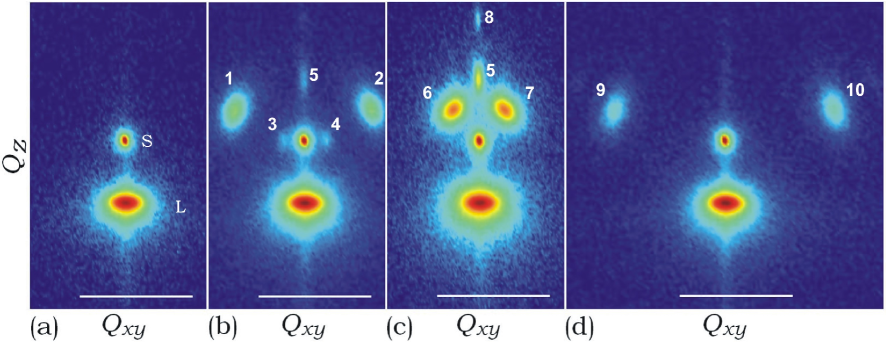
Occurrence of experimental HRLPs is demonstrated in Fig. 3, obtained in a sample with a single m thick ZnSe epilayer on GaAs (001) substrate. Proper identification of the HRLPs is given in Table 1. The reciprocal-space maps were collected on a Philips X’Pert-MRD high resolution diffractometer: Cu tube, X-ray mirror, four-crystal asymmetric 220 Ge monochromator and three-bounce 220 Ge analyzer crystal; nominal spectral width ; X-ray beam divergences and in the incidence plane and in the axial direction, respectively.
Direct and complete strain analysis of the epilayer is possible even from reciprocal-space maps of the symmetric 002 GaAs reflection when HRLPs are excited. The components of the HRLPs in Figs. 3(b), 3(c), and 3(d) are well reproduced by using Å-1, and their longitudinal separation (an integer fraction of the layer-substrate reciprocal-lattice point distance) provides Å-1. Hence, assuming a Poisson ratio of , which implies , the fully relaxed lattice parameter of the layer compound is obtained as Å, which is the same as the nominal value of the ZnSe compound, while the epilayer undergoes an expansive in-plane strain .
HRLPs in Fig. 3(d), numbers 10 and 11, have the largest observed component, scattering within a theoretical takeoff angle , equation (7), but still accepted by the analyzer system of the diffractometer. In fact, the minimum required acceptance of the analyzer system should be, in general, equal or larger than the axial divergence since the experimental takeoff angles are increased by an amount corresponding to the difference between and values in Table 1. For instance, HRLPs 3 and 4 would not appear on the map in Fig. 3(b) if the axial acceptance was below .
HRLPs with null component, such as those numbered 5, 8, and 9 in Figs. 3(b) and 3(c), can not be related to second-order sequences of reflections. hybrid reflections do not occur for partially or fully relaxed epilayers on (001) substrates because and in equation (4) have non-null values. Sequences of third-order, such as and can explain the and type of HRLP even in relaxed layers. Note that when carrying out longitudinal scans, i.e. scans, HRLPs along the primary reflection axis generate extra features even in samples with a single epilayer. Moreover, in ordinary rocking curves, hybrid intensity contributions could be misinterpreted as due to sublayers or other sort of structural change, such as composition grading.
Two hypotheses have been verified to explain the elongated shapes of the experimental HRLPs in Fig. 3. The strain grading hypothesis should, according to equation (8), reduce the absolute value of as the in-plane component of increases. The expected values of , calculated using , are given in Table 1. Although elongations happen in the same sense as the observed ones, their behavior as the indexes increase is the opposite of that expected. For instance, , , and , are the expected values for the HRLPs numbered 6, 1, and 10, while the observed values are instead , , and .
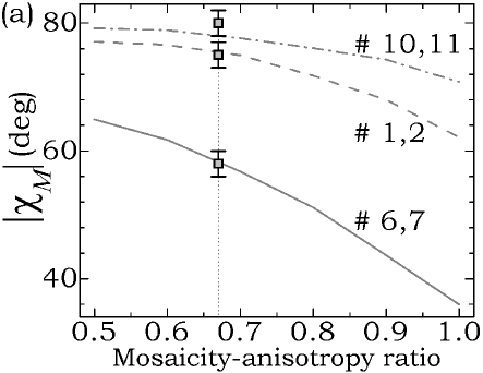
A successful explanation for the elliptical shapes of the HRLPs comes from mosaicity in the epilayer. Its 002 reciprocal-lattice point in Fig. 3 (spot labeled L) has a full width at half-maximum (FWHM) of Å-1 along the coordinate, yielding an out-plane mosaic width of . Fig. 4(a) shows the computed directions of maximum projection of the vector onto the maps, described by the angle , equation (11), as a function of mosaicity-anisotropy ratio . A very good match to the experimental values is obtained for a ratio of , as can be seen by comparing and in Table 1, and then, . Projection shapes for this ratio value is given in Fig. 4(b). In theory (Fig. 4a), hybrid reflections of indexes and , HRLPs 6 and 7, have better sensitivity to the in-plane mosaicity, and they are used to estimate the error bar of the found ratio value.
IV Conclusions
Hybrid reciprocal lattices for x-ray diffraction in epilayer/substrate systems exist. Without a systematic description, as the one provided in this work, accidental excitement of hybrid reflections in most X-ray diffraction techniques can jeopardize data analysis. On the other hand, understanding their properties leads to three-dimensional information of the layer structure even in symmetrical high-angle diffraction geometries. In the case analyzed here, from reciprocal-space maps of a single symmetric reflection we were able to determine parallel and perpendicular lattice mismatches, the stress state of the epilayer, the absence of strain grading, and the spatial misorientation of mosaic grains in the layer.
Appendix A Bragg condition for hybrid reflections
Let us initially consider a given three-beam diffraction of the substrate lattice in which . In the reference system where , is an arbitrarily chosen in-plane direction perpendicular to , and , the incident beam wavevector
| (12) |
fulfills the two Bragg conditions in equations (1) and (2) when and . Hence, is the Bragg angle of the primary reflection, diffraction vector , and can be calculated by the expression
| (13) |
given that .
The problem is how to calculate the exact incidence, , and azimuthal, , angles of a hybrid reflection whose effective diffraction vector is . Since is not parallel to the axis, equation (13) is no longer valid for either or diffraction vectors of the secondary reflection. To solve this problem we first wrote (Morelhão, 2002)
| (14) |
and then equations (2) and (3) were used to build the system of linear equations
| (15) |
where and stand for and , respectively.
The values in Table 1 were calculated by solving the above equations. For instance, consider the HRLP, line 7 in Table 1. Since the 002 GaAs reflection is the primary one and the [110] crystallographic direction was chosen as reference for the rotation,
The corresponding substrate three-beam diffraction occurs at
as obtained from equation (13) since , , and . The and angles provide the wavevector from equation (12), as well as and . By replacing in equation (15)
with Å, Å, and Å, we have
which leads to in Table 1.
Acknowledgements.
Thanks are due to Vaclav Holý (Charles University, Prague, Czech Republic) for helpful discussions, and to the European Community program C1MA-CT-2002-4017 (Centre of Excellence CEPHEUS) for partial support. SLM also acknowledges founding from Brazilian agencies CNPq (proc. No. 301617/1995-3) and CAPES/GRICES (proc. No. 140/05).References
- (1) Caticha-Ellis, S. (1969). Acta Cryst. A25, 666–673.
- (2) Chang, S.L. (1980). Appl. Phys. Lett. 37, 819–821.
- (3) Chang, S.L. (1984). Multiple Diffraction of X-rays in Crystals. Heidelberg: Springer-Verlag.
- (4) Cole, H., Chambers, F.W. & Dunn, H.M. (1962). Acta Cryst. 15, 138–144.
- (5) Colella, R. (1974). Acta Cryst. A30, 413–423.
- (6) Domagala, J.Z., Holý, V., Sadowski, J., Minikayev, R., Romanowski, P., Bak-Misiuk, J., Caliebe, W., Szuszkiewicz, W. & Pelka, J. (2006). Proceedings of the 8th Biennal Conference on High Resolution X-ray Diffraction and Imaging (unpublished).
- (7) Hayashi, M.A., Morelhão, S.L., Avanci, L.H., Cardoso, L.P., Sasaki, J.M., Kretly, L.C. & Chang, S.L. (1997). Appl. Phys. Lett. 71, 2614–2616.
- (8) Isherwood, B.J., Brown, B.R., & Halliwell, M.A.G. (1981). J. Cryst. Growth 54, 449–460.
- (9) Morelhão, S.L., Avanci, L.H., Hayashi, M.A., Cardoso, L.P. & Collins, S.P. (1998). Appl. Phys. Lett. 73, 2194–2196.
- (10) Morelhão, S.L., Avanci, L.H., Quivy, A.A. & Abramof, E. (2002). J. Appl. Cryst. 35, 69–74.
- (11) Morelhão, S.L.& Cardoso, L.P. (1991). J. Cryst. Growth 110, 543–552.
- (12) Morelhão, S.L. & Cardoso, L.P. (1993a). J. Appl. Phys. 73, 4218–4226.
- (13) Morelhão, S.L. & Cardoso, L.P. (1993b). Solid State Commun. 88, 465–469.
- (14) Morelhão, S.L., Cardoso, L.P., Sasaki, J.M. & Carvalho, M.M.G. (1991). J. Appl. Phys. 70, 2589–2593.
- (15) Morelhão, S.L., Quivy, A.A., & Härtwig, J. (2003). Microelectron. J. 34, 695–699.
- (16) Renninger, M. (1937). Z. Phys. 106, 141–176.
- (17) Weckert, E. & Hümmer, K. (1997). Acta Cryst. A53, 108–143.