Modelling contact angle hysteresis on chemically patterned and superhydrophobic surfaces
Abstract
We investigate contact angle hysteresis on chemically patterned and superhydrophobic surfaces, as the drop volume is quasi-statically increased and decreased. We consider both two, and three, dimensions using analytical and numerical approaches to minimise the free energy of the drop. In two dimensions we find, in agreement with other authors, a slip, jump, stick motion of the contact line. In three dimensions this behaviour persists, but the position and magnitude of the contact line jumps are sensitive to the details of the surface patterning. In two dimensions we identify analytically the advancing and receding contact angles on the different surfaces and we use numerical insights to argue that these provide bounds for the three dimensional cases. We present explicit simulations to show that a simple average over the disorder is not sufficient to predict the details of the contact angle hysteresis, and to support an explanation for the low contact angle hysteresis of suspended drops on superhydrophobic surfaces.
I Introduction
Our aim in this paper is to investigate contact angle hysteresis on chemically patterned and superhydrophobic surfaces. For a surface that is flat and chemically homogeneous, a liquid drop will form a spherical cap with a contact angle given by Young’s law Young
| (1) |
where , and and the gas–solid, liquid–solid and liquid–gas surface tensions respectively. This shape corresponds to the minimum free energy configuration of the system, assuming that the drop size is much smaller than the capillary length so that gravity can be neglected.
Real surfaces are, however, neither perfectly flat nor chemically homogeneous. These inhomogeneities result in the existence of multiple local free energy minima, not just the global minimum prescribed by Young’s formula (1). This can cause pinning of the contact line and lead to drop shapes which depend not only on the thermodynamic variables describing the state of the drop, but also on the path by which that state was achieved. This phenomenon is known as contact angle hysteresis.
There are several different manifestations of contact angle hysteresis commonly reported in the literature and it is important to distinguish clearly between them. One favoured experimental approach to measure the contact angle of a drop is to slowly increase the volume until the drop starts to spread. The angle at which spreading occurs, which corresponds to the drop being able to cross any free energy barrier which impedes its motion, is termed the advancing contact angle. Similarly, as the drop volume is quasi-statically decreased, the contact line first moves at the receding contact angle. The difference between the advancing and receding contact angles is the contact angle hysteresis, zero for a perfect substrate, but possibly or more, and notoriously difficult to measure, for a real surface. We shall concentrate on this set-up here and shall term it unforced, static hysteresis.
It is also possible to push a drop across a surface and measure the advancing angle, at the front of the drop, and the receding contact angle, at the rear, when it first moves. We shall refer to this case as forced, static hysteresis and comment on it further in the discussion. However it is important to point out that the measured unforced and forced contact angle hystersis for a given drop on a given surface need not necessarily be the same as a forced drop will be deformed and the free energy barriers will depend on the shape of the drop.
In the literature there is also mention of dynamic contact angle hysteresis, the difference in angles at the front and rear of a moving drop. This is again a different situation, which cannot be treated by equilibrium statistical mechanics, and we shall not consider it further here.
Understanding contact angle hysteresis quantitatively is not easy because it depends on the details of the surface inhomogeneities which will, in general, be random in position and size. However recent advances have allowed surfaces to be fabricated with well-defined chemical patterning – areas of differing contact angle – which can be varied in size relative to the size of a drop (e.g. Lenz1 ; Darhuber1 ; Leopoldes1 ). This is allowing more quantitative measurements of how advancing and receding contact angles, and contact angle hysteresis, depend on the details of the surface patterning.
Another exciting development is the fabrication of superhydrophobic surfaces Quere1 ; Quere2 ; McCarthy1 . When surfaces with an intrinsic hydrophobic contact angle are covered with micron scale posts, the macroscopic contact angle increases to, in certain cases, close to . Drops can either lie in a suspended, or Cassie-Baxter Cassie , state on top of the posts or a collapsed, or Wenzel Wenzel , state filling the interstices between them. Moreover on these surfaces, drops can roll very easily Quere1 ; Quere2 ; McCarthy1 ; McCarthy2 ; McCarthy3 and contact angle hysteresis is important in understanding why. It is of interest to ask how the position, size and spacing of the posts affects the hysteresis, questions which have caused some controversy in the literature McCarthy1 ; McCarthy2 ; McCarthy3 ; McHale1 ; Extrand , for example whether contact angle hysteresis is primarily a surface (e.g. McHale1 ), or a contact line (e.g. McCarthy1 ; McCarthy2 ; McCarthy3 ; Extrand ), effect. Very recent experiments by Dorrer et al. Dorrer show that the advancing contact angle is constant, while the receding contact angle varies as a function of the post size and spacing.
The role of free energy barriers in contact angle hysteresis has been known for some time Derjaguin ; deGennes2 ; Iwamatsu1 ; Johnson1 ; Huh1 ; Johnson3 ; Marmur1 ; Marmur3 ; Huh2 ; Amirfazli ; Schwartz1 ; Schwartz2 ; deGennes1 ; Marmur2 ; Chatain1 ; Kong . Several authors have considered the two dimensional (or axisymmetric three dimensional) problem of a drop moving over chemically striped surfaces Iwamatsu1 ; Johnson1 , sinusoidal surfaces Huh1 ; Johnson3 ; Marmur1 ; Marmur3 , or surfaces with posts Huh2 ; Amirfazli using analytic or numerical techniques to minimise the free energy. Extensions to three dimensions have also been attempted Johnson1 ; deGennes1 ; Marmur2 ; Chatain1 ; Kong ; Schwartz1 ; Schwartz2 . These efforts include surfaces with random isolated heterogeneities deGennes1 , striped patterns Marmur2 , and regular lattices of posts Chatain1 ; Kong or chemical patches Johnson1 ; Schwartz1 ; Schwartz2 . The common themes in all these works are the pinning of the contact line, the existence of multiple local energy minima, and the occurence of a slip-jump-stick behaviour.
In this paper we investigate contact angle hysteresis on chemically patterned and superhydrophobic surfaces, as the drop volume is quasi-statically increased and decreased. We consider both two, and three, dimensions using analytical and numerical approaches to minimise the free energy of the drop. In two dimensions, on a surface striped with regions of different equilibrium contact angle, , we find, in agreement with other authors Iwamatsu1 ; Johnson1 , a slip, jump, stick motion of the contact line. The advancing and receding contact angles are equal to the maximum and minimum values of the respectively. In three dimensions these values provide bounds, but the contact angle hysteresis is reduced by the free energy associated with surface distortion Schwartz1 ; Schwartz2 ; deGennes1 . A stick, slip, jump behaviour persists, but we caution that the definition of a single macroscopic contact angle is problematic for patterns of order the drop size. The position and magnitude of the contact line jumps are sensitive to the details of the surface patterning and can be different in different directions relative to that patterning.
For drops suspended on superhydrophobic surfaces we find that, in two dimensions, the advancing contact angle is (ideally) , in agreement with Huh2 and the receding angle is , the intrinsic contact angle of the surface. For collapsed drops in two dimensions the advancing contact angle is also but the receding angle is because the contact line has to dewet the sides of the posts. In three dimensions, for both suspended and collapsed drops, the advancing angle remains close to McCarthy1 ; McCarthy2 ; McCarthy3 ; Dorrer ; Chatain1 , but the receding contact angle is increased. However, the receding angle still remains considerably smaller for the collapsed state and the contact line pinning is much stonger for the collapsed state. As a result, the hysteresis of suspended drops is, in general, much smaller than that of collapsed drops on the same surface. Again we argue that a simple average over the disorder is not sufficient to predict the details of the contact angle hysteresis.
We organise the paper as follows: in the next section we list the equations describing the dynamics and thermodynamics of the drops we consider. We briefly describe the lattice Boltzmann algorithm used to solve these equations and, in particular, the numerical scheme employed to incrementally add or remove the drop volume. In sections III and IV, we focus on chemically patterned surfaces. We then discuss topologically patterned surfaces in sections V–VII treating first the suspended, and then the collapsed, state. In each case we consider two, and then three, dimensions. Section IX summarises our conclusions and discusses areas for future research.
II The model drop
We choose to model the equilibrium properties of the drop by a continuum free energy Briant1
| (2) |
is a bulk free energy term which we take to be Briant1
| (3) |
where , and , , , and are the local density, critical density, local temperature, critical temperature and critical pressure of the fluid respectively. This choice of free energy leads to two coexisting bulk phases of density , which represent the liquid drop and surrounding gas respectively. Varying has the effects of varying the densities, surface tension, and interface width; we typically choose .
The second term in Eq. (2) models the free energy associated with any interfaces in the system. is related to the liquid–gas surface tension and interface width via and Briant1 . Unless stated otherwise, we use , , , and .
The last term in Eq. (2) describes the interactions between the fluid and the solid surface. Following Cahn Cahn the surface energy density is taken to be , where is the value of the fluid density at the surface. The strength of interaction, and hence the local equilibrium contact angle, is parameterised by the variable . Minimising the free energy (2) leads to the boundary condition at the surface,
| (4) |
and a relation between and the equilibrium contact angle Briant1
| (5) |
where and the function sign returns the sign of its argument. On chemically heterogeneous surfaces the contact angle will be a function of position. This can be modelled easily within a simulation by using Eq. (5) to calculate the appropriate value of and then constraining the normal derivative at different regions of the surface to take the appropriate values, given by Eq. (4). Similar boundary conditions can be used for surfaces that are not flat: a way to treat the corners and ridges needed to model superhydrophobic surfaces is described in Dupuis2 .
The equations of motion of the drop are the continuity and the Navier-Stokes equations
| (6) | |||
| (7) |
where , , , and are the local velocity, pressure tensor, kinematic viscosity, and acceleration respectively. The thermodynamic properties of the drop appear in the equations of motion through the pressure tensor which can be calculated from the free energy Briant1 ; Dupuis2
| (8) | |||
| (9) |
When the drop is at rest and the free energy (2) is minimised .
We use a lattice Boltzmann algorithm to solve Eqs. (6) and (7). No-slip boundary conditions on the velocity are imposed on the surfaces adjacent to and opposite the drop and periodic boundary conditions are used in the two perpendicular directions. Details of the lattice Boltzmann approach and of its application to drop dynamics are given in Briant1 ; Dupuis2 ; Leopoldes1 ; Succi1 ; Yeomans .
To implement unforced static hysteresis we need to slowly increase or decrease the drop volume. To do this we vary the drop liquid density by . This in turn affects the drop volume as the system relaxes back to its coexisting equilibrium densities. Forced hysteresis can be addressed by imposing a body force in the Navier-Stokes equation (7).
III Two dimensional drop on a chemically patterned surface
In this section we shall investigate a two-dimensional situation, the hysteresis of a cylindrical drop spreading over a chemically striped surface, where an analytic solution is possible. We shall demonstrate that the contact line shows a stick, jump, slip behaviour and that the advancing and receding contact angles are equal to the maximum and minimum equilibrium contact angles of the surface respectively. We also show that lattice Boltzmann simulations reproduce the analytic results well.
Consider a cylindrical drop with a macroscopic contact angle that forms a spherical cap of radius as shown in Fig. 1. (Note that we reserve , , and to describe the equilibrium, advancing, and receding contact angles on a given surface.) The base length of the drop is . The drop volume per unit length is
| (10) |
and therefore, for a drop at constant volume,
| (11) |
The liquid–gas surface area per unit length is
| (12) |
The important contributions to the free energy per unit length of the cylindrical drop come from the interfacial terms:
| (13) |
where the integral is taken over the substrate. Using Young’s equation (1) the reduced free energy follows as
| (14) |
We consider, as in Johnson3 ; Iwamatsu1 , the simple case where a drop is lying on a surface regularly patterned with (relatively) hydrophilic stripes with equilibrium contact angle and width and (relatively) hydrophobic stripes with parameters and width . Let us further assume that the contact line is initially lying on a hydrophilic stripe. Our aim is to discuss the motion of the contact line as the drop volume slowly increases. The drop initially lies at an angle with respect to the solid surface. As the volume is increased the contact line moves in order to keep the contact angle at a value . This remains true until the contact line reaches the chemical border between stripes. It will then be pinned as it costs free energy for the drop to spread onto the more hydrophobic stripe. The contact line will continue to be pinned until the free energy cost of distorting the liquid–gas interface exceeds the surface energy gain. We demonstrate that, as expected, this occurs when Iwamatsu1 ; Johnson1 .
From Eq. (14) we may write the reduced free energy of the drop as
| (15) |
where is an integer and . Moving the drop a small distance onto the hydrophobic stripe the free energy changes by
| (16) |
which, using the constant volume constraint (Eq. (11)) can be rewritten
| (17) |
Hence and the drop depins when .
Increasing the volume further the drop contact line moves with a constant contact angle . Once the drop reaches the hydrophobic–hydrophilic chemical border it can lower its free energy by immediately spreading onto the hydrophilic stripe. It will either move to a position where the contact angle has returned to or to the next hydrophilic–hydrophobic boundary, whichever is reached first. In the particular examples we show below, the latter is the case and the contact line becomes pinned at the next hydrophilic-hydrophobic border, with a contact angle .
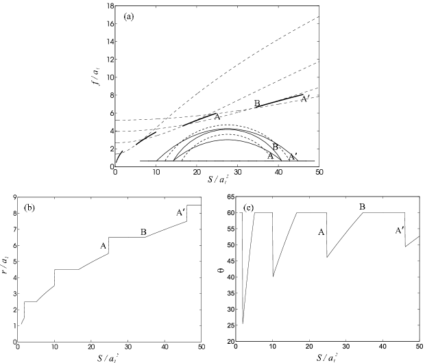
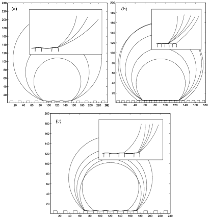
The free energy (14) of the advancing drop is illustrated in Fig. 2(a) for , and . The dashed lines show the free energy of the drop pinned at successive hydrophilic–hydrophobic boundaries as the drop volume is increased. The solid line shows the path in free energy space taken by the drop as it spreads with a contact angle . At A the drop reaches, and immediately wets the hydrophilic stripe corresponding to a sudden fall in free energy. It reaches the hydrophobic boundary and remains pinned along AB. At B the contact angle attains the value and the drop spreads across the hydrophobic stripe, reaching the next hydrophilic stripe at A′. The solid lines in the inset in Fig. 2(a) show the drop profiles at A, B and A′. The dashed lines in the inset correspond to the drop profiles at A and A′ immediately before contact line jumps occur. The drop base length and contact angle as a function of volume are plotted for the advancing contact line in Fig. 2(b) and (c). The stick, slip, jump behaviour will be a recurrent theme for all the substrates we consider.
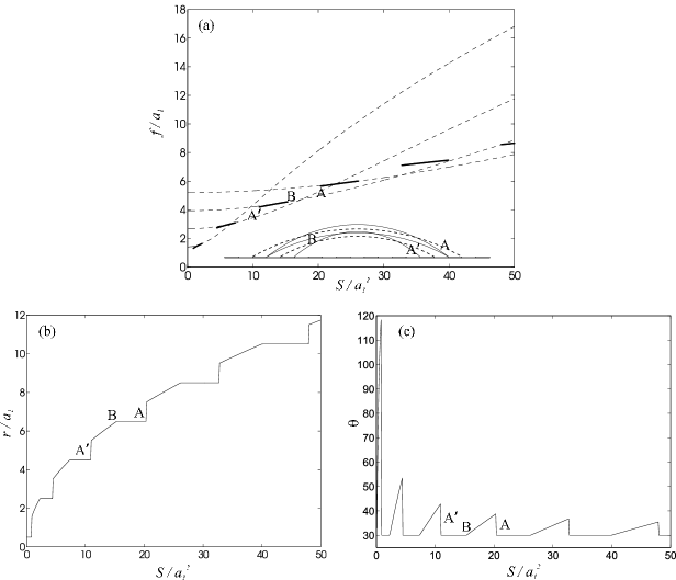
Similar reasoning can be applied to understand the dynamics of the receding contact line. Free energy curves for this case are shown in Fig. 3(a). (As this is the receding contact angle, the correct way to read the plot is from right to left.) Assume that the contact line is initially placed on the hydrophobic stripe with . As the volume of the drop is reduced, the contact line will recede smoothly to the hydrophobic–hydrophilic border where it remains pinned until Iwamatsu1 ; Johnson1 (along AB in Fig. 3(a)). The contact line then continues to move along the hydrophilic stripe with contact angle (BA′). A sudden jump occurs when it reaches the hydrophilic–hydrophobic border as the drop can lower its free energy by dewetting the hydrophobic stripe (at A′ in Fig. 3(a)). The inset in Fig. 3(a) show the profile of the drop as its volume is reduced. The drop base length and contact angle as a function of volume are shown in Fig. 3 (b) and (c).
Fig. 4 shows a typical hysteresis curve: the variation of the macroscopic contact angle as the volume is increased, then decreased. Diagonal, horizontal, and vertical lines correspond to the drop sticking, slipping, and jumping respectively. The data points are results from the lattice Boltzmann simulations, while the solid line corresponds to the analytical calculations. The contact line dynamics is well captured by lattice Boltzmann simulations, though contact line jumps occur earlier in lattice Boltzmann simulations than one would expect from the analytical expressions. This is because the numerical interface has a finite width, typically lattice spacings.
We can conclude that for unforced hysteresis on a two dimensional chemically striped surface, the advancing contact angle and the receding contact angle . If we return to the free energy curves in Fig 2(a) and 3(a), paths AB and BA′ are reversible. Even though contact line pinning is observed there, the contact angle is unique for a given drop volume. It is the free energy jumps at A and A′ that make contact angle hysteresis an irreversible phenomenon.
IV Three dimensional drop on a chemically patterned surface
In section III, we showed that and for a two dimensional drop on a chemically striped surface. We now turn to three dimensions. Here we find that the values of the advancing and receding contact angles are strongly dependent on the details of the surface patterning. Therefore we shall focus on the general aspects of the hysteresis, particularly those not captured by the two dimensional model described in section III, rather than quantitative details. The drops no longer form spherical caps so analytic results are not possible without serious approximation. Our arguments will be illustrated by numerical results obtained using lattice Boltzmann simulations of the model described in Section II.
The chemically patterned surface we consider is shown diagrammatically in Fig. 5. Squares of side are separated by a distance . In the first case that we consider (surface A), the equilibrium contact angle of the squares is taken as , while that of the channels between them is . In the second case (surface B), we swapped the values of the equilibrium contact angles so that for the squares and for the channels. Due to the particular choice of and , the two surfaces have almost the same macroscopic contact angle, calculated using the Cassie-Baxter formula
| (18) |
which averages over the surface contact angles. and are the fractions of the surface with intrinsic equilibrium contact angle and respectively. Therefore we might naively expect the two surfaces to have very similar behaviour. However, this is not the case unless the strength of the heterogeneities is below a certain threshold deGennes2 ; deGennes1 , a condition which implies negligible contact angle hysteresis.
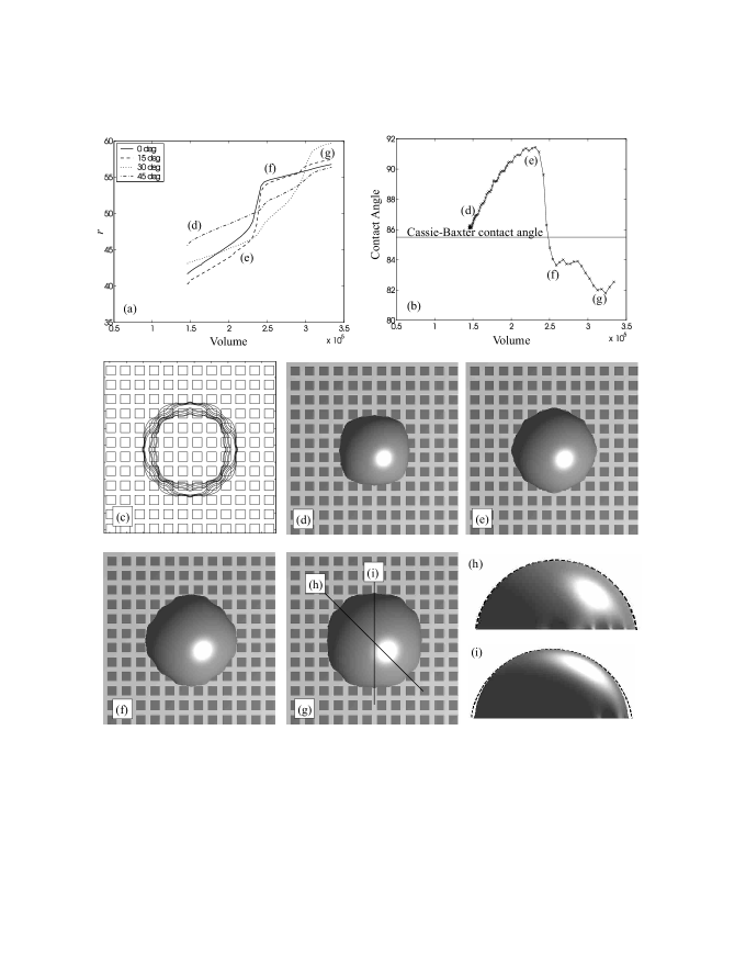
Consider first the advancing contact angle. From the discussions in Section III, we know that contact line pinning occurs because there is an energy barrier for the drop to move onto a hydrophobic area, whilst the contact line jumps when it reaches a new hydrophilic region. Therefore we expect to observe stick behaviour when the contact line reaches unwetted hydrophobic parts of the surface, slip when it moves across partially covered hydrophobic portions, and jumps as the contact line reaches the hydrophilic areas. This is indeed observed in the lattice Boltzmann simulations, as shown by the plots of the base radius of the drop at different volumes in Figs. 6(c) and 7(c) for surfaces A and B respectively.
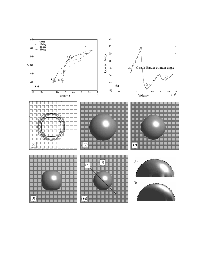
Since the contact line is no longer circular the local contact angle varies along the contact line and the notion of a macroscopic contact angle pertaining to the whole drop is not well defined. However, a popular approach (e.g. Chatain1 ) is to match the drop profile far away from the substrate to a spherical cap to obtain the drop radius of curvature, and hence define a macroscopic contact angle
| (19) |
where is the drop height and is the radius of curvature at the top of the spherical cap. If the length scales of the heterogeneities are of order the interface width then one expects Eq. (19) to give a value of equal to the Cassie-Baxter contact angle. However, as we see in Figs. 6 – 7, this is not necessarily the case for the length scales considered here. Indeed, in some of the metastable states the drop shape is far from a spherical cap and therefore it makes little sense to define a macroscopic contact angle. As a guide to the accuracy of the definition (19), Figs. 6 – 7 (h–i) show the side views of the largest (for advancing contact angle) or smallest (for receding contact angle) simulated drops at two different viewing angles, with the dashed lines showing the corresponding spherical fit. In general, the fit is better for the diagonal cross sections as compared to the vertical or horizontal cross sections. This is because along the diagonal direction it is very disadvantageous for the contact line to lie entirely in the hydrophilic region. As a result, contact line pinning is weaker, and the drop interface is more able to take a circular shape. The top view of the drops are shown in Figs. 6 – 7 (g).
With these cautions the macroscopic contact angle, defined by Eq. 19 is plotted as a function of drop volume in Figs. 6 – 7 (b). Fig. 6 gives the results for surface A and Fig. 7 for surface B. The overall behaviour of the curves is reminiscent of that for the two dimensional case in Fig. 2. However changes in slope are rounded and there is secondary structure that depends on the details of the surface patterning, and on the shape and position of the contact line. This is an important new feature of the three dimensional geometry; that the slip-stick-jump behaviour can occur at different volumes in different directions, leading to secondary structure in the base radius and contact angle plots. This underlines the importance of using multiple viewing angles when measuring the advancing and receding contact angles on patterned surfaces.
The behaviour of the different directions is, however, correlated. This can be seen in Figs. 6(a) and 7(a), where the variation of the interface position is plotted against volume at several angles with respect to the lattice axes. For example, any variation in the drop radius at is typically accompanied by a similar variation at , although the drop radius at does not necessarily follow the same trend. Essentially this more complex motion of the drop in three dimensions occurs because the contact line lies on both hydrophobic and hydrophilic portions of the surface to avoid large surface distortions which would lead to a large liquid–gas surface free energy penalty. The shape of the contact line is thus very complicated and can be approximated analytically only in a few special cases Schwartz1 ; Schwartz2 . Nevertheless, as one would qualitatively expect, the simulation results show that the sections of contact line which lie on hydrophobic areas are concave whilst those on hydrophilic regions are convex.
We now compare the behaviour on surfaces A and B. Results for surface A are shown in Fig. 6. As its volume increases the drop wishes to move onto the hydrophilic channels between the hydrophobic patches, but prefers to also cover part of the hydrophobic regions to avoid significant interface distortion. As a result, the drop tends to be facetted. The first, larger, jump in contact angle in Fig. 6(b) occurs when the contact line reaches the hydrophilic channels in the vertical and horizontal directions. The contact line moves more easily in the diagonal directions and the second, smaller, jump is due to the sudden movement of the contact line along the diagonal.
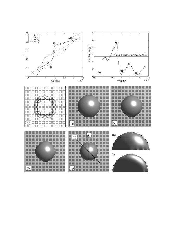
Contact line pinning is more pronounced on surface B (see Fig. 7). There is a relatively high free energy barrier to move onto the hydrophobic channels and hence contact line jumps occur at higher contact angles. As a corollary of this the free energy release and the jump in contact angle upon depinning is also higher for surface B. From Figs. 6 and 7, the jumps can be read off as and for surfaces A and B respectively. Indeed even the order of the stick-slip-jump behaviour is not neccesarily the same. For the simulations we have presented in Figs. 6 and 7, the order is stick-slip-jump on surface A, whereas on surface B, it is stick-jump-slip.
Similar results for the receding contact angles are presented in Figs. 8 and 9 for surfaces A and B respectively. Comparing the contour plots for the advancing and receding contact line, we find that contact line pinning occurs at very similar positions: for surface A, when the drop tries to dewet the hydrophilic channel, and for surface B, as it dewets the square hydrophilic patches. Since the free energy barrier is highest in the vertical or horizontal directions, the primary features of the curves are caused by contact line pinning in these directions. The secondary features are due to the contact line dynamics in the diagonal directions. Again, this is similar to the behaviour as the drop advances. It is important to realise, however, that this is only a qualitative similarity. The receding jumps occur at different volumes and have magnitudes and for surfaces A and B respectively. Figs. 6(b) and 8(b) also provide a clear example that the secondary structures can be different for the advancing and receding contact angles.
In two dimensions the advancing and receding contact angles were and (here and ). In three dimensions, these values are reduced by the additional surface free energy penalty caused by distortions of the drop. On surfaces A and B, are and respectively, bounded by and the Cassie-Baxter contact angle . The receding contact angles are and for surfaces A and B and are bounded by and . We therefore find that contact angle hysteresis is slightly larger for surface B () than for surface A (). We expect this discrepancy to become larger if the wettability contrast between the hydrophilic and hydrophobic patches is increased and future work will explore both this and the dependence of contact angle on patch size. The initial positioning of the drop with respect to the hydrophobic grid will change the quantitative details of the behaviour, but we expect the qualitative descriptions we have here to remain true.
V Two dimensional suspended drop on a topologically patterned surface
We now consider unforced hysteresis on a topologically patterned surface that consists of an array of posts as shown in Fig. 10; this is a typical fabricated superhydrophobic surface. It is well-established that such topological heterogeneities amplify the hydrophobicity of the surface Quere1 ; Quere2 . There are two ways in which this can occur. When the drop is suspended on top of the surface roughness, as shown in Fig. 10(a), the substrate is effectively a composite of liquid-solid and liquid-gas sections. If the length scale of the posts is much smaller than the drop size, averaging over the corresponding interfacial energies is equivalent to putting (of the posts) and in the Cassie-Baxter equation (18) to give a macroscopic contact angle equation Cassie
| (20) |
where is the solid (area) fraction of the substrate. On the other hand, if the liquid drop fills the space between the posts, as shown in Fig. 10(b), the liquid-solid contact area is increased by a roughness factor , and the macroscopic contact angle is given by the Wenzel equation Wenzel
| (21) |
This is called the collapsed state. Both the Wenzel and Cassie-Baxter formulae give reasonable estimates for the values of the contact angle. However, as they only take account of the average properties of the susbtrate and do not address the problem of multiple local free energy minima, their relevance in understanding contact angle hysteresis will be limited.
In this section, we concentrate on a two dimensional suspended drop, showing that the advancing and receding contact angles are and respectively Huh2 . We then, in section VI, treat the two-dimensional collapsed drop. Here the hysteresis is larger with and equal to and . The extension to three dimensions will be discussed in section VII and VIII for the suspended and collapsed drops respectively.
As the drop retains the shape of a circular cap above the posts, the free energy calculations described in Section III can be adapted to explore the way in which the contact line moves as the volume of the drop is slowly increased or decreased. The argument is analogous to that for the chemically striped surface if we take to be the equilibrium contact angle of the posts and to be the liquid–gas interface contact angle, which is equal to . Hence we expect the advancing and receding contact angles to be and respectively. For a finite value of base radius , the contact angle will reach only as . As a result, the contact line will remain pinned indefinitely at the outer edge of a given post as the drop volume is increased.
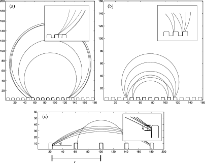
These predictions are consistent with lattice Boltzmann simulations as shown in Fig. 11(a). In this set of simulations, we used a post width , post separation , and an equilibrium contact angle . The drop volume increased by about a factor 4, and the contact angle to , and no transition was observed. At this point it was no longer possible to run the simulation as the drop filled the simulation box. As the drop volume was decreased (Fig. 11(c)) the drop jumped between posts at . We do not find that the receding drop establishes its equilibrium contact angle on the side of the asperities as proposed by Extrand Extrand .
If the separation between the posts was decreased to (with ), however, we did observe a contact line jump from one post to another as shown in Fig. 11(b). The contact angle of the drop just before the jump was . This is due to the diffuse liquid–gas interface in the lattice Boltzmann simulations which allows the interface to probe the existence of the neighbouring post and hence lower its free energy by jumping across to it. To check this interpretation we ran a simulation increasing from to corresponding to a wider interface. This led to a decrease in the advancing contact angle from to .
In the model, the interface width is comparable to the dimensions of the posts, a problem inherent in mesoscale simulations of multiphase fluids. This is not true for typical superhydrophobic surfaces where the posts are m in size. Nevertheless, in real systems, there are likely to be mechanical vibrations Garoff1 , surface imperfections, and thermal fluctuations Kong , which will cause the contact line to feel the neighbouring posts. Gravity will also lower the liquid–gas interface and hence makes it easier to touch the neighbouring posts.
VI Two dimensional collapsed drop on a topologically patterned surface
We now discuss unforced hysteresis for a cylindrical collapsed drop where the gaps between the posts are filled with liquid. When the drop volume is increased the advancing contact angle is and the drop behaves in the same way as for the suspended state. This is because locally, in the vicinity of the contact line, the drop has no information as to whether it is in the collapsed or suspended state. Indeed, in the two dimensional simulations we have run, if the contact line does advance, the grooves are not filled by the liquid drop as the contact line advances from one post to the next, in contradiction to the work of Li et al. Amirfazli , which assumes that the gap is filled as the contact line advances. The results are shown in Fig. 12(a) for , , , and , the same parameters as in Fig. 11(b). In a perfect system there should be no advancing jump between posts. We see a transition at for the collapsed drop because of the diffuseness of the interface. This is consistent with the results in Fig. 11(b) where a contact line jump was seen at for the suspended drop.
Next we consider the way in which the contact line recedes as the drop volume decreases. The typical behaviour is shown in Fig. 12(b). As for the suspended drop, the contact line is pinned at the outer edge of a post until . It then retreats smoothly across the post. However, unlike the suspended case, the contact line is pinned again at the inner edge of the posts. This happens because the free energy gain from the reduced liquid–gas interface of the circular cap is not large enough to dewet the side walls of the posts.
To demonstrate this we recall that drop free energy has two important contributions. The first comes from the liquid–gas interface of the circular cap, while the second is from the liquid–solid boundary.
| (22) |
where , , and are respectively the base radius, the macroscopic contact angle, and the distance from the inner edge of the posts to the contact line. These are illustrated in Fig. 12(c). Taking the first derivative of gives
| (23) |
For a drop of a constant volume
and hence to are related by
| (24) |
Subsituting Eq. (24) into Eq. (23) gives
| (25) |
The condition implies that pinning will hold at the top of the posts as long as . This is best seen in Fig. 12(c) where the posts’ separation has been increased to to facilitate the measurement of the receding contact angle. The drop is found to recede at , consistent with the expected analytical result . We note that this is equivalent to the criteria first proposed by Gibbs Gibbs and confirmed experimentally by Oliver et al. Huh2 .
Once this condition is satisfied, further reduction in the drop volume will cause the drop to steadily dewet the side of the post. If the posts are short, the contact line will touch the base of the interstices and it will quickly retract to the neighbouring posts. If the posts are tall, however, the liquid–gas interface can intersect the corners of the neighbouring post, in which case satellite drops will be formed in between the posts. In either case, the contact line will typically reach the next post and move to its inner edge without regaining a contact angle . Therefore the behaviour will typically be stick-jump rather than stick-jump-slip. Furthermore, comparing this motion to that described for the suspended drop in section V shows that, in this simple two dimensional model, the contact angle hysteresis is larger for the collapsed state than for the suspended state.
VII Three dimensional suspended drop on a topologically patterned surface
The two dimensional model discussed in Section V and VI captured the phenomenon of contact line pinning on topologically patterned surfaces but the three phase contact line was only represented by two points at the ends of the liquid–gas interface. Hence we were unable to address the effect of distortions of the contact line caused by the surface roughness. Therfore we now present results from three dimensional lattice Boltzmann simulations aimed at investigating contact angle hysteresis on three dimensional topologically patterned surfaces.
For the suspended state we used , , , and which, using the Cassie-Baxter formula (20), gives an estimate of for the macroscopic contact angle. The very high value of the drop contact angle is challenging for the simulations because a small change in the contact angle requires a large change in the drop volume. Moreover, since one needs the drop to be suspended on a reasonable number of posts, a huge simulation box is needed. We used 168 x 168 x 168 lattice points and the largest drop simulated had a volume of .
Small deviations in the drop shape near the surface (from a spherical cap) can cause large uncertainties in the contact angle measurements. The definition in Eq. (19) gives for the drops modelled in this section. We therefore use
| (26) |
where is the height of the drop and is the maximum base radius, as an alternative definition of macroscopic contact angle.
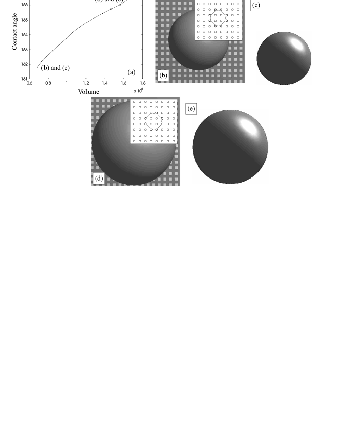
Fig. 13 (a) shows the drop contact angle as a function of volume. In the simulation, we have quasi-statically increased the volume from to . This gives a macroscopic contact angle (Eq. (26)) which ranges from to . At least for the range of volumes simulated the contact line remains pinned as suggested by other groups McCarthy1 ; McCarthy2 ; McCarthy3 ; Chatain1 ; Dorrer and consistent with our two dimensional arguments that the contact line jump occurs when or when the interface is able to touch the neighbouring posts. In Fig. 13(b–e) the contour plot, top view, and side view of the drop at the beginning and at the end of the simulation are shown.
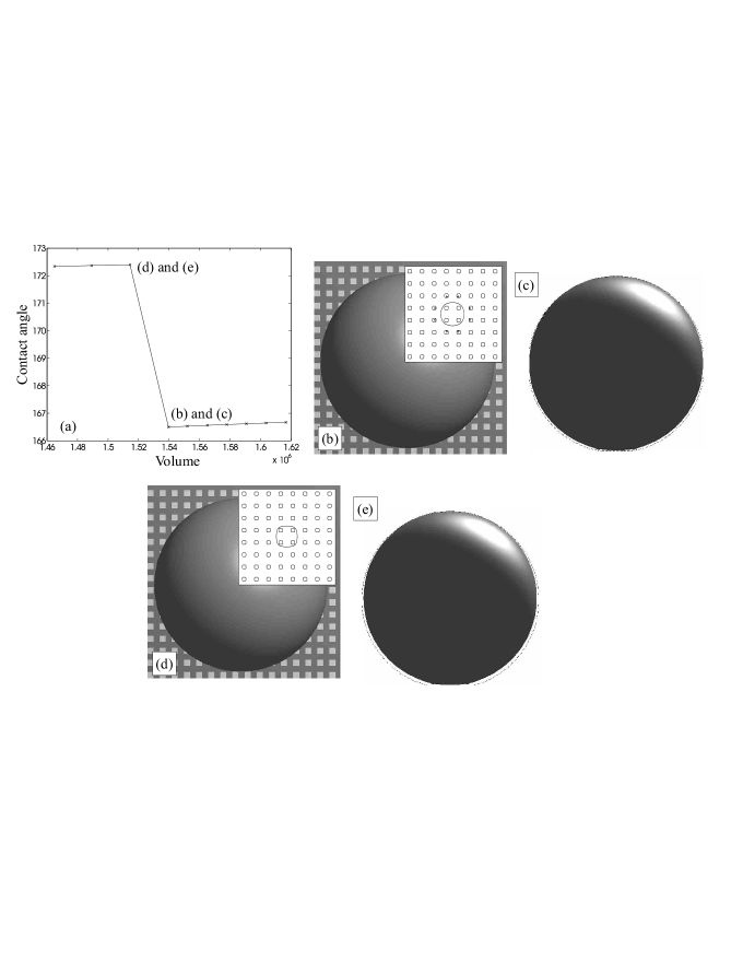
While the contact line is very difficult to advance, it is a lot easier to recede. We reduce the drop volume by reducing the liquid density by around and then let the system to relax to a (local) minimum energy state. For the parameters used here, the receding contact line jump occurs at (), as shown in Fig. 14(a). This high value of the receding angle implies that the receding contact line is very unstable against small perturbations, highlighting the weak adhesion of suspended drops on superhydrophobic surfaces. Indeed even the small volume changes we used in the simulations tended to make the drop detach slightly from the surface. The receding contact line can be made even less stable by reducing the solid fraction or by increasing the hydrophobicity of the posts McCarthy1 ; McCarthy2 . The contour plot, top view, and side view of the drop before and after the contact line jump are shown in Fig. 14(b–e).
VIII Three dimensional collapsed drop on a topologically patterned surface
We now turn our attention to the collapsed state where the space between the posts is filled with liquid. We use , , , and , which according to the Wenzel formula (21) gives a contact angle .
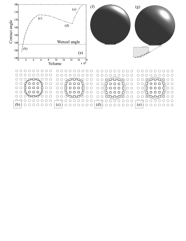
Fig. 15(a) shows the macroscopic contact angle of the drop, calculated using the definition (19), as a function of increasing volume. Initially the contact angle increases because, even though the contact line moves outwards in the diagonal direction (with respect to the posts), it remains pinned in the horizontal and vertical directions. This can be seen in the contour plots shown in Fig. 15(b–c). Once the drop has touched the four neighbouring posts along the diagonals, it wets the top of these posts (Fig. 15(d–e)) and this allows the contact angle to decrease slightly, by about . At this stage the contact line will again be pinned until it is energetically favourable to jump and wet the neighbouring posts in the vertical and horizontal directions. This will become possible when the drop can feel the neighbouring posts. We note that this contact line jump has not occured in the simulations we have presented here. Increasing the size of the simulation box was prohibitively expensive in computer time
Typical side views of the drops are shown in Fig. 15(f–g), with the dashed line showing the corresponding spherical fits. The fitted curves match well with drop profiles above the posts, but not with the profiles in between the posts. This again emphasises that any definition of macroscopic contact angle is arbitrary and should be treated with caution. In this section, the contact angle is calculated at the intersection between the fitted curve and the base surface. If instead we take the intersection between the fitted curve and the top of the posts, the values of the contact angles would be lower. This will however, not change the trends we describe in this section.
In section VI, we found that, in two dimensions, the receding contact angle for the collapsed state is because of the adhesion provided by the sides of the posts. In three dimensions, we expect the adhesion effect to remain relevant. However, the corresponding energy barrier will now be lowered by the free energy costs due to the liquid–gas interfaces between the posts.
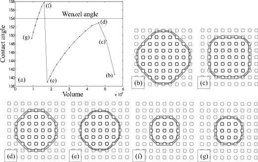
The drop’s macroscopic contact angle as a function of decreasing volume is shown in Fig. 16(a). The general features of the curve are very similar to the other examples of receding contact line dynamics that we have discussed. The contact angle decreases slowly as volume is reduced (Fig. 16(d–e) and Figs. 16(f–g)) until any further reduction in drop volume makes it more favourable for the drop to depin its contact line (Figs. 16(b–d) and 16(e–f)). Naturally, as a result of the contact line jump, the contact angle increases very sharply. Taking the lowest (highest) value of the contact angle in Fig. 16(a) (Fig. 15(a)) as the receding (advancing) contact angle, we obtain , and .
IX Discussion
In this paper we described contact angle hysteresis on both chemically patterned and superhydrophobic surfaces as the drop volume was quasi-statically increased or decreased. We first considered the two dimensional case of a cylindical drop. This is a useful baseline calculation as the models are tractable analytically and contain many features that carry over to three dimensions. It was also useful to check the results of lattice Boltzmann simulations against the two dimensional results. The simulation approach was then used to explore the full, three dimensional problem.
For chemically patterned surfaces in two dimensions the advancing (receding) contact angle is equal to the maximum (minimum) value of the equilibrium contact angle. In three dimensions these parameters act as bounds on the hysteresis. Extra free energy contributions, which result from the distortion of the surface, decrease the advancing, and increase the receding, contact angles, thus decreasing the contact angle hysteresis.
For superhydrophobic surfaces in two dimensions the advancing contact angle is close to for both suspended and collapsed drops. The drop will only advance when it is able to feel the neighbouring posts because of, for example, finite interface width or mechanical vibration. This remains true in three dimensions.
The receding contact angle is, however, very different for the suspended and collapsed states. In two dimensions, for suspended drops, it is equal to the contact angle of the posts . For the collapsed state it is equal to because the interface needs to move down the sides of the posts to recede. In three dimensions these angles again provide limiting values.
For a suspended drop, to obtain a low contact angle hysteresis, the receding angle needs to be driven as close to as possible McCarthy1 ; McCarthy2 . This can be done by making as large as is feasible and then choosing the surface patterning to distort the drop so that the free energy barriers are lowered. For the collapsed state, contact line pinning is stronger and hence we expect the receding contact angle to be lower and the contact angle hysteresis to be larger. This is observed experimentally (e.g. Quere1 ; Quere2 ; McCarthy1 ) and is related to the very different adhesive properties of the suspended and collapsed states. To increase the receding contact angle, one can increase , increase the posts’ separation, or decrease the posts’ size.
It is important to note that, because of the distorted drop shape, the advancing and receding contact angles depend on the direction in which the measurement is taken; indeed the concept of macroscopic contact angle is a matter of definition. They also depend sensitively on the details of the surface patterning and any average over the area of the patterning or over the angle along the contact line is not sufficient to predict the hysteretic properties of a surface. We also note that when the contact line jump involves more than one post (or chemical patch), it does not wet/dewet the posts simulatenously. For the advancing drop, movement starts at the centre post, while for the receding drop, the contact line first dewets the outer posts. This is in agreement with deGennes2 ; Schwartz1 ; Schwartz2 ; Dorrer .
It will be of interest to compare the results we have presented here for unforced hysteresis, where the drop volume is changed quasi-statically, to what we will term forced hysteresis, where the drop is pushed by, for example, a body force. The aim is to slowly increase the force and discuss the value of the advancing and receding contact angles at which the drop first starts to move. Because we are working in the limit of zero velocity free energy arguments can still be used.
On a flat, perfectly smooth surface the limiting force is zero and the drop will start to move as soon as it is pushed. On a patterned surface there will be pinning. The problem is, however, now much more complicated than for unforced hysteresis as the free energy barriers, of which there might be many, depend not only on the local surface patterning, but also on the overall shape of the drop. This in turn will depend on the size of the drop and the magnitude and details of the applied force. Therefore we expect that, in general, the advancing and receeding contact angles will differ from those of unforced hysteresis and that they will depend sensitively on the details of the problem. Preliminary results indicate that the stick-slip-jump behaviour is still observed, both in two and three dimensions. In general the depinning of the front and back contact line occur at different times, as opposed to the simultaneous depinning seen in the unforced case.
The aim will then be to consider dynamic hysteresis, the effect of free energy barriers on the motion of a drop. This is now a dynamical problem which will depend on the equations of motion of the drop as well as its static properties. For the results presented in this paper the full lattice Boltzmann formalism is not needed, except to follow the motion of a drop during a jump and to aid relaxation to equilibrium. However, we wanted to use it to allow an immediate generalisation to dynamical problems. A fuller investigation of forced and dynamic hysteresis will be presented elsewhere.
There are many other directions for future work. Among these are the effects of random patterning on the advancing and receding contact angle and any differences that may arise from having smooth, rather than abrupt, junctions between regions of different contact angle. It would also be interesting to perform simulations to more fully explore the dependence of contact angle hysteresis on the size and spacing of the posts and chemical patches.
Acknowledgements
We thank G. A. D. Briggs, A. Dupuis, G. McHale, D. Quéré and R. J. Vrancken for useful discussions. HK acknowledges support from a Clarendon Bursary.
References
- (1) Young, T. Philos. Trans. R. Soc. London 1805, 95, 65.
- (2) Gau, G.; Hermingaus, H.; Lenz P.; Lipowsky, R. Science 1999, 283, 46.
- (3) Darhuber, A. A.; Troian, S. M.; Miller, S. M.; Wagner, S. J. Appl. Phys. 2000, 87, 7768.
- (4) Léopoldès J.; Dupuis, A.; Yeomans, J. M. Langmuir 2003, 19, 9818.
- (5) Quéré, D. Physica A 2002, 313, 32.
- (6) Quéré, D. Rep. Prog. Phys. 2005, 68, 2495.
- (7) On̈er, D.; McCarthy, T. J. Langmuir, 2002, 16, 7777;
- (8) Cassie A. B. D.; Baxter, S. Trans. Faraday Soc. 1944, 40, 546.
- (9) Wenzel, R. N. Ind. Eng. Chem. 1936, 28, 988.
- (10) Gao, L.; McCarthy, T. J. Langmuir, 2006, 22, 2966;
- (11) Gao, L.; McCarthy, T. J. Langmuir, 2006, 22, 6234.
- (12) McHale, G.; Shirtcliffe, N. J.; Newton, M. I. Langmuir 2004, 20, 10146.
- (13) Extrand, C. W. Langmuir 2002, 18, 7991.
- (14) Dorrer, C.; Rühe, J. Langmuir 2006, 22, 7652.
- (15) Derjaguin, B. V. C. R. Acad. Sci. USSR. 1946, 51, 361.
- (16) de Gennes, P. G. Rev. Mod. Phys. 1985, 57, 827.
- (17) Iwamatsu, M. J. Coll. Interf. Sci. 2006, 297, 772.
- (18) Johnson, R. E.; Dettre, R. H. Advan. Chem. Ser. 1964, 43, 112.
- (19) Huh C.; Mason, S. G. J. Coll. Interf. Sci. 1977, 60, 11.
- (20) Johnson, R. E.; Dettre, R. H. J. Phys. Chem. 1964, 68, 1744.
- (21) Marmur, A. J. Coll. Interf. Sci. 1994, 168, 40.
- (22) Brandon, S.; Marmur, A. J. Coll. Inter. Sci. 1996, 183, 351.
- (23) Oliver, J. F.; Huh, C.; Mason, S. G. J. Coll. Interf. Sci. 1977, 59, 568.
- (24) Li, W.; Amirfazli, A. J. Coll. Interf. Sci. 2001, 292, 195.
- (25) Joanny, J. F.; de Gennes, P. G. J. Chem. Phys. 1984, 81, 552.
- (26) Brandon, S.; Wachs, A.; Marmur, A. J. Coll. Inter. Sci. 1997, 191, 110.
- (27) Chatain, D.; Lewis, D.; Baland, J-P; Carter, W. C. Langmuir 2006, 22, 4237.
- (28) Kong, B.; Yang, X. Langmuir 2006, 22, 2065.
- (29) Schwartz, L. W.; Garoff, S. Langmuir 1985, 1, 219;
- (30) Schwartz L. W.; Garoff, S. J. Coll. Interf. Sci. 1985, 106, 422.
- (31) Briant, A. J.; Wagner, A. J.; Yeomans, J. M. Phys. Rev. E 2004, 69, 031602;
- (32) Cahn, J.W. J. Chem. Phys. 1977, 66, 3667.
- (33) Dupuis, A.; Yeomans, J.M. Langmuir 2005, 21, 2624.
- (34) Succi, S. The Lattice Boltzmann Equation, For Fluid Dynamics and Beyond; OUP: 2001.
- (35) Yeomans, J. M. Physica A: Statistical Mechanics and Its Applications 2006, 369, 159.
- (36) Decker, E. L.; Frank, B.; Suo, Y.; Garoff, S. Colloids Surfaces A: Physiochem. Eng. Aspects 1999, 156, 177.
- (37) Gibbs, J. W. Scientific Papers 1906, Dover reprint; Dover: New York (1961).
FIGURE CAPTIONS
Fig. 1: Schematic diagram of a cylindrical drop.
Fig. 2: The dynamics of the advancing contact line for , and . (a) Free energy, (b) drop radius, and (c) macroscopic contact angle as a function of drop size. A and A′: the contact line immediately wets the hydrophilic stripe. AB: the contact line is pinned until . BA′: the contact line advances with . The inset in (a) summarises the evolution of the drop shape. The solid lines in the inset show the drop profiles at A, B and A′, while the dashed lines correspond to the drop profiles at A and A′ immediately before contact line jumps occur.
Fig. 3: The dynamics of the receding contact line for , and . (a) Free energy, (b) drop radius, and (c) macroscopic contact angle as a function of drop size. A and A′: the contact line immediately dewets the hydrophobic stripe. AB: the contact line is pinned until . BA′: the contact line recedes with . The inset in (a) summarises the evolution of the drop shape. The solid lines in the inset show the drop profiles at A, B and A′, while the dashed lines correspond to the drop profiles at A and A′ immediately before contact line jumps occur.
Fig. 4: Hysteresis curve for a two dimensional, cylindrical drop on a chemically striped surface. , and . The data points are results from the lattice Boltzmann simulations and the solid line corresponds to the analytical calculations.
Fig. 5: Schematic diagram of the chemically patterned surface.
Fig. 6: Advancing contact line dynamics for surface A, where squares with and length are separated by a distance , on a background with . (a) Volume dependence of the interface position at an angle , , , and with respect to the lattice axes. (b) Macroscopic contact angle as a function of drop volume. (c) Contour plots of the base radius at various drop volumes. (d-g) Top view of the drops at the points indicated in frame (b). (h-i) Side views of the drop as indicated in frame (g).
Fig. 7: Advancing contact line dynamics for surface B, where squares with and length are separated by a distance , on a background with . (a) Volume dependence of the interface position at an angle , , , and with respect to the lattice axes. (b) Macroscopic contact angle as a function of drop volume. (c) Contour plots of the base radius at various drop volumes. (d-g) Top view of the drops at the points indicated in frame (b). (h-i) Side views of the drop as indicated in frame (g).
Fig. 8: Receding contact line dynamics for surface A, where squares with and length are separated by a distance , on a background with . (a) Volume dependence of the interface position at an angle , , , and with respect to the lattice axes. (b) Macroscopic contact angle as a function of drop volume. (c) Contour plots of the base radius at various drop volumes. (d-g) Top view of the drops at the points indicated in frame (b). (h-i) Side views of the drop as indicated in frame (g).
Fig. 9: Receding contact line dynamics for surface B, where squares with and length are separated by a distance , on a background with . (a) Volume dependence of the interface position at an angle , , , and with respect to the lattice axes. (b) Macroscopic contact angle as a function of drop volume. (c) Contour plots of the base radius at various drop volumes. (d-g) Top view of the drops at the points indicated in frame (b). (h-i) Side views of the drop as indicated in frame (g).
Fig. 10: Schematic diagram of a cylindrical drop on a topologically patterned surface: (a) suspended state and (b) collapsed state.
Fig. 11: Drop shape as a function of time from lattice Boltzmann simulations of a cylindrical drop suspended on a topologically patterned surface. (a) The advancing contact line remains pinned during the simulation ( and ). (b) A contact line jump occurs when ( and ). (c) The measured receding contact angle ( and ). The position of the contact lines can be seen more clearly in the insets.
Fig. 12: Drop shape as a function of time from lattice Boltzmann simulations of a cylindrical drop collapsed on a topologically patterned surface showing the contact line motion as the drop volume is (a) increased or (b-c) decreased. (a) and (b): , and . (c): , , and . The equilibrium contact angle . The position of the contact lines can be seen more clearly in the insets.
Fig. 13: Advancing contact line dynamics for a suspended drop on a superhydrophobic surface with , , , and . (a) Contact angle as a function of volume. (b) and (c) Top and side view of the drop at . (d) and (e) Top and side view of the drop at . The insets in frame (b) and (d) are the corresponding contour plots of the base of the drop.
Fig. 14: Receding contact line dynamics for a suspended drop on a superhydrophobic surface with , , , and . (a) Contact angle as a function of volume. (b) and (c) Top and side view of the drop at . (d) and (e) Top and side view of the drop at . The insets in frame (b) and (d) are the corresponding contour plots of the base of the drop.
Fig. 15: Advancing contact line dynamics for a collapsed drop on a superhydrophobic surface with , , , and . (a) Contact angle as a function of volume. (b–e) Contour plots of the drop at positions indicated in (a): the different lines correspond to heights 1, 3, 5, and 6 lattice spacings away from the bottom surface. (f) The drop cross section in the horizontal direction. (g) The drop cross section in the diagonal direction. The spherical fit is shown by the dashed lines and the inset magnifies the spherical fit close to the posts.
Fig. 16: Receding contact line dynamics for a collapsed drop on a superhydrophobic surface with , , , and . (a) Contact angle as a function of volume. (b–e) Contour plots of the drop at positions indicated in (a): the different lines correspond to heights 1, 3, 5, and 6 lattice spacings away from the bottom surface.