Tuning of the spin-orbit interaction in two-dimensional GaAs holes via strain
Abstract
We report direct measurements of the spin-orbit interaction induced spin-splitting in a modulation-doped GaAs two-dimensional hole system as a function of anisotropic, in-plane strain. The change in spin-subband densities reveals a remarkably strong dependence of the spin-splitting on strain, with up to about % enhancement of the splitting upon the application of only about strain. The results are in very good agreement with our numerical calculations of the strain-induced spin-splitting.
pacs:
Valid PACS appear hereManipulation of the spin-orbit coupling in materials that lack inversion symmetry is considered the basis for novel spintronic devices DattaAPL90 ; NittaAPL99 ; Reviews . In two dimensions, these devices utilize the fact that the inversion asymmetry of the confining potential can be tuned with a perpendicular electric field applied via external front- and back-gate biases RashbaJP84 ; NittaPRL97 ; LuPRL98 ; PapadakisSCI99 ; PapadakisPHE01 ; Winkler03 . This structural inversion asymmetry, along with the bulk inversion asymmetry of the zinc-blende structure, leads to a lifting of the spin degeneracy of the energy bands even in the absence of an applied magnetic field. The energy bands at finite wave vectors are split into two spin subbands with different energy surfaces, populations, and effective masses. It is the manipulation of this so-called zero-field spin-splitting that forms the underlying principal of many spintronic devices. In addition, the spin-orbit interaction-induced spin-splitting is of interest in studying fundamental phenomena such as Berry’s phase MorpurgoPRL98 ; YauPRL02 and the spin Hall effect EngelsCM06 .
There have been recent reports of utilizing strain for tuning the spin-orbit interaction and the resulting spin-splitting KatoNat04 ; SihPRB06 ; CrookerPRL05 ; BeckCM06 . The studies have focused on magneto-optical (Faraday/Kerr rotation) measurements in epitaxially grown but bulk-doped GaAs and InGaAs electron systems. Here we present strain-induced spin-splitting results for a high-mobility, modulation-doped GaAs two-dimensional hole system (2DHS). We utilize a simple but powerful technique to continuously apply quantitatively measurable in-plane strain in-situ ShayeganAPL03 , and make magneto-transport measurements which directly probe the densities of the spin-subbands. We observe a significant change in spin-splitting as a function of strain. The experimental data agree very well with our accurate numerical calculations of the spin-splitting which take the spin-orbit interaction and strain fully into account. We show that the mechanism that gives rise to the strain-induced spin-splitting in hole systems is qualitatively different from the meachanism operating in electron systems. Most importantly, the strain enhancement of the spin-splitting for the 2D holes is about 100 times larger than for 2D electrons and, moreover, is essentially independent of the strain direction. Combined, our results establish the extreme sensitivity of the spin-orbit coupling in 2DHSs to strain, and demonstrate the potential use of the 2D holes for spintronic and related applications.
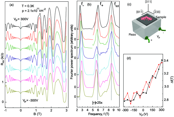
Our sample was grown on a GaAs (311)A substrate by molecular beam epitaxy and contains a modulation-doped 2DHS confined to a GaAs/AlGaAs heterostructure. The Al0.35Ga0.65As/GaAs interface is separated from a 17 nm-thick Si-doped Al0.35Ga0.65As layer (Si concentration of cm-3) by a 30 nm Al0.35Ga0.65As spacer layer. We fabricated L-shaped Hall bar samples via photo-lithography and used In:Zn alloyed at 440∘C for the ohmic contacts. Metal gates were deposited on the sample’s front and back to control the 2D hole density (). We measured the longitudinal () and transverse () magneto-resistances at K via a standard low frequency lock-in technique. was measured along [] and [] directions yielding, at cm-2, low temperature mobilities of cm2/Vs and cm2/Vs in the two directions respectively. Here we present data along []; Measurements along [] reveal similar results.
We apply tunable strain to the sample by gluing it on one side of a commercial piezoelectric (piezo) stack actuator with the sample’s [] crystal direction aligned with the poling direction of the piezo [Fig. 1(c)] ShayeganAPL03 . When bias is applied to the piezo-stack, it expands (shrinks) along the [] for () and shrinks (expands) along the [] direction. We have confirmed that this deformation is fully transmitted to the sample, and using metal strain gauges glued to the opposite side of the piezo, have measured its magnitude ShayeganAPL03 ; GunawanCM06 . Based on our calibrations of similar piezo-actuators, we estimate a strain of along the poling direction. In the perpendicular direction, the strain is approximately times the strain in the poling direction ShayeganAPL03 . In this paper we specify strain values along the poling direction; we can achieve a strain range of about by applying to the piezo. Finally, the back-gate on the sample is kept at a constant voltage throughout the measurements to shield the 2DHS from the electric field of the piezo-stack.
Figure 1(a) shows the low-field Shubnikov-de Haas (SdH) oscillations for seven different values of from V to V in steps of V. The Fourier transform spectra of these oscillations, shown in Fig. 1(b), exhibit three dominant peaks at frequencies , , and , with the relation . The frequency, when multiplied by , matches well the total 2D hole density deduced from the Hall resistance ( is the electron charge and is the Planck constant). The two peaks at and correspond to the Fermi contours of holes in individual spin-subbands although their positions times do not exactly give the spin-subband densities Winkler03 ; WinklerPRL00 ; KeppelerPRL02 . As we discuss below, however, this discrepancy between and the spin-subband densities is minor and indeed provides a very good measure of the spin-splitting. The vertical gray lines in Fig. 1(b) clearly indicate that increases when the piezo voltage is dialed up from V to V while the total hole density () remains constant. Figure 1(d) summarizes the change in with strain (in terms of piezo-bias) for cm-2; determined from both () and () are plotted. The results show a significant (about 20%) enhancement of spin-splitting with strain.
In order to understand the data of Fig. 1, we performed self-consistent calculations of the spin-splitting as a function of strain, using the Kane Hamiltonian augmented by the strain Hamiltonian of Bir and Pikus Bir74 ; TrebinPRB79 ; Winkler03 . This model takes into account the spin-orbit coupling due to both the structure inversion asymmetry of the GaAs/AlGaAs hetero-junction as well as the bulk inversion asymmetry of the underlying zinc blende structure WinklerPRB93 . Furthermore, it fully incorporates the strain-induced contributions to spin-splitting. We adapted this model to the (311) orientation of our sample by a suitable coordinate transformation. To make a direct comparison with the experimental data, we calculated the Landau fan chart for and determined the magneto-oscillations of the density of states at the Fermi energy WinklerPRL00 ; Winkler03 . We then calculated the Fourier power spectrum of these oscillations and obtained the frequencies and that correspond to the majority and minority spin subbands. The difference between these frequencies can be directly compared to the experimentally determined data of Fig. 1(d).
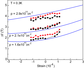
Figure 2 presents our calculated (solid curves) as a function of strain for three different 2DHS densities. It is clear that the calculated exhibit substantial changes with strain. In Fig. 2 we also show the measured values for the same three densities, assuming that corresponds to zero strain. There is overall very good agreement between the calculated and measured . The agreement is particularly remarkable in view of the fact that the calculations were performed only based on the sample structure and density. In other words, there are no fitting parameters used to match the results of the calculations to the measured values of .
We would like to make the following remarks about the results presented in Fig. 2. First, it is known that WinklerPRL00 ; KeppelerPRL02 the frequencies and are not exactly related to the spin subband densities at zero magnetic field, and , via the relation , although this relation approximately holds. For completeness, we also calculated and . We find that for the data shown in Fig. 2, the calculated is only slightly larger than the calculated , by at most 10%. This means that the results presented in Fig. 2 closely represent the spin-splitting at zero magnetic field as well. Second, although there are no fitting parameters in comparing the experimental and calculated , we do have an experimental uncertainty regarding the absolute value of strain. In our experiments, we know the relative changes in values of strain accurately, but we do not know the piezo-bias corresponding to zero-strain. Thanks to a mismatch between the thermal expansion coefficients of GaAs and the piezo-stack, at low temperatures the sample can be under finite strain even at . This residual strain is cooldown-dependent and unfortunately we do not know its magnitude for the data of Fig. 2 which were measured during a single cooldown. Based on our experience with cooldowns of samples glued to similar piezo-stacks, we expect a residual strain up to about GunawanCM06 ; ShkolnikovAPL04 . If we assume that there is indeed a finite residual strain in our experiment, and shift the experimental data points in Fig. 2 horizontally to the right by about , we would find better agreement between the calculated and measured for the and cm-2 data; the agreement for cm-2 data, however, worsens. We emphasize that despite this uncertainty regarding the exact value of the zero-strain condition in our study, the overall agreement of the experimental and calculated spin-splitting, including its strain dependence, is remarkable.
Our analysis reveals that the mechanism leading to the strain dependence of spin-splitting in 2DHSs is very different from the mechanism responsible for the strain-dependent spin-splitting in bulk-like electron systems studied previously KatoNat04 ; SihPRB06 ; CrookerPRL05 ; BeckCM06 . In the latter case, strain has generally only a weak effect on the energy dispersion, and the spin-splitting can be traced back to a small deformation potential, often denoted as that couples electron and hole states in a spin-dependent manner TrebinPRB79 . Furthermore, the strain dependence is highly anisotropic. No spin-splitting occurs for strain along the crystallographic [100] direction CrookerPRL05 ; BeckCM06 . In 2DHSs, on the other hand, the piezo-induced strain has a two-fold effect. First it changes the heavy-hole light-hole (HH-LH) energy splitting. Since spin-splitting in 2DHSs is known to compete with the HH-LH splitting Winkler03 , this provides a direct way to tune the spin-splitting. Second, the strain changes the functional form of the spin-splitting of 2DHSs. While in the absence of strain the spin-splitting of 2DHSs is cubic in the wave vector Winkler03 , strain gives rise to a significant spin-splitting linear in . The deformation potentials relevant for these effects (often denoted as and TrebinPRB79 ) are much more important than which is the reason why the strain dependence of spin-splitting is much more pronounced in hole systems as compared to electron systems. Also, the strain-induced spin-splitting in 2DHSs depends only weakly on the direction of the in-plane strain. The effect of the spin-dependent deformation potential on the spin-splitting of hole states is much smaller than the effects discussed here.
For a more quantitative comparison, we deduce the spin splitting in a 2D GaAs electron system at a density of cm-2 by using Eq. (6.18) in Ref. Winkler03 . The change in spin-subband densities for this system for an applied strain of is cm-2. From Fig. 2 the corresponding change in spin-subband densities for our sample is cm-2. This is 100 times larger than the 2D electron system Footnote2DEG .
We close by highlighting a potential application of our findings. Our results reveal a surprisingly large change in spin-splitting in GaAs 2D holes for rather small values of applied strain. This tuning of the spin-splitting can be employed to demonstrate various spintronic and/or spin-interference effects in devices, such as Aharonov-Bohm type ring structures, made in this system. In the spin interference device proposed by Nitta et al. NittaAPL99 , e.g., the conductance through a ring of radius a is expected to oscillate with a period of , where denotes the change in , defined as the difference of the Fermi wave vectors of the two spin-subbands. In our 2DHS sample, at cm-2, the strain-induced change in is m-1 Footnotedk . Hence for a ring of radius nm, the conductance through the ring would go through one period of oscillation. For such measurements, tuning the spin-orbit interaction via strain, rather than perpendicular electric field (gate bias), may prove advantageous: the 2D hole density remains fixed as a function of strain, thus simplifying the experimental measurements and their interpretation Footnote1 .
After the completion of this work we learned of related results by Kolokolov et al. KolokolovPRB99 who studied the strain dependence of the spin-splitting in GaAs (100) 2DHSs. Their experimental data, however, are only in qualitative agreement with their calculations.
We thank the DOE, ARO, NSF and the Alexander von Humboldt Foundation for support.
References
- (1)
- (2) S. Datta and B. Das, Appl. Phys. Lett. 56, 665 (1990).
- (3) J. Nitta, F. Meijer, and H. Takayanagi, Appl. Phys. Lett. 75, 695 (1999).
- (4) For reviews, see e.g., G.A. Prinz, Physics Today 48, 58 (1995); S.A. Wolf, D.D. Awschalom, R.A. Buhrman, J.M. Daughton, S. von Molnar, M.L. Roukes, A.Y. Chtchelkanova, and D.M. Treger, Science 294, 1488 (2001); I. Zutic, J. Fabian and S. Das Sarma, Reviews of Modern Physics 76, 323 (2004).
- (5) Y. A. Bychkov and E. I. Rashba, J. Phys. C 17, 6039 (1984).
- (6) J. Nitta, T. Akazaki, H. Takayanagi, and T. Enoki, Phys. Rev. Lett. 78, 1335 (1997).
- (7) J. P. Lu, J. B. Yau, S. P. Shukla, M. Shayegan, L. Wissinger, U. Rössler, and R. Winkler, Phys. Rev. Lett. 81, 1282 (1998).
- (8) S. J. Papadakis, E. P. De Poortere, H. C. Manoharan, M. Shayegan, and R. Winkler, Science 283, 2056 (1999).
- (9) S. J. Papadakis, E. P. De Poortere, M. Shayegan, and R. Winkler, Physica E 9, 31 (2001).
- (10) R. Winkler, Spin-Orbit Coupling Effects in Two-Dimensional Electron and Hole Systems, (Springer, Berlin, 2003).
- (11) A. F. Morpurgo, J. P. Heida, T. M. Klapwijk, B. J. van Wees, and G. Borghs, Phys. Rev. Lett. 80, 1050 (1998).
- (12) Jeng-Bang Yau, E. P. De Poortere, and M. Shayegan, Phys. Rev. Lett. 88, 146801 (2002).
- (13) H. Engels, E. Rashba and B. Halperin, cond-mat/0603306 (2006).
- (14) Y. Kato, R.C. Myers, A.C. Gossard, and D.D. Awschalom, Nature 427, 50 (2004).
- (15) S. A. Crooker and D. L. Smith, Phys. Rev. Lett. 94, 236601 (2005).
- (16) V. Sih, H. Knotz, J. Stephens, V. R. Horowitz, A. C. Gossard, and D. D. Awschalom, Phys. Rev. B73, 241316(R) (2006).
- (17) M. Beck, C. Metzner, S. Malzer, and G.H. Doehler, cond-mat/0504668 (2006).
- (18) M. Shayegan, K. Karrai, Y. P. Shkolnikov, K. Vakili, E. P. De Poortere, and S. Manus, Appl. Phys. Lett. 83, 5235 (2003).
- (19) O. Gunawan, Y. P. Shkolnikov, K. Vakili, T. Gokmen, E. P. De Poortere, M. Shayegan, cond-mat/0605692, (2006).
- (20) S. Keppeler and R. Winkler, Phys. Rev. Lett. 88, 046401 (2002).
- (21) R. Winkler, S. J. Papadakis, E. P. De Poortere, and M. Shayegan, Phys. Rev. Lett. 84, 713 (2000).
- (22) G. L. Bir and G. E. Pikus, Symmetry and strain-induced effects in semiconductors, (Wiley, New York, 1974).
- (23) H.-R. Trebin, U. Rössler, and R. Ranvaud, Phys. Rev. B 20, 686 (1979).
- (24) R. Winkler and U. Rössler, Phys. Rev. B 48, 8918 (1993).
- (25) R. Winkler, H. Noh, E. Tutuc, and M. Shayegan, Phys. Rev. B65, 155303 (2002).
- (26) Y. P. Shkolnikov, K. Vakili, E. P. De Poortere, and M. Shayegan, Appl. Phys. Lett. 85 3766 (2004).
- (27) In Eq. (6.18) of Ref. [9], we replaced the Rashba coefficient by , where epsilon is the applied strain, and is the deformation potential (linearly proportional to ) that couples the electron spin to the strain. We used eVÅ, taken from G. E. Pikus and A. N. Titkov, in Optical Orientation, edited by F. Meier and B. P. Zakharchenya, (North-Holland, Amsterdam, 1984), p. 73.
- (28) is deduced from the spin-subband densities by assuming an isotropic dispersion giving . This simplifying assumption helps in understanding the ring experiment qualitatively. A more detailed analysis would require taking the anisotrpy of the HH band into account.
- (29) Tuning the spin-splitting via gate bias has the often undesired result of changing the total 2D density and therefore the number of conducting channels in the ring.
- (30) K.I. Kolokolov, A.M. Savin, S.D. Beneslavski, N.Ya. Minina and O.P. Hansen, Phys. Rev. B59 7537 (1999)