Computer simulation of fatigue under diametrical compression
Abstract
We study the fatigue fracture of disordered materials by means of computer simulations of a discrete element model. We extend a two-dimensional fracture model to capture the microscopic mechanisms relevant for fatigue, and we simulate the diametric compression of a disc shape specimen under a constant external force. The model allows to follow the development of the fracture process on the macro- and micro-level varying the relative influence of the mechanisms of damage accumulation over the load history and healing of microcracks. As a specific example we consider recent experimental results on the fatigue fracture of asphalt. Our numerical simulations show that for intermediate applied loads the lifetime of the specimen presents a power law behavior. Under the effect of healing, more prominent for small loads compared to the tensile strength of the material, the lifetime of the sample increases and a fatigue limit emerges below which no macroscopic failure occurs. The numerical results are in a good qualitative agreement with the experimental findings.
pacs:
46.50.+a,62.20.Mk,05.10.-aI Introduction
Understanding the fatigue damage process of disordered materials is obviously important in many areas. The time scales related to the failure process, the relevant damage mechanisms, and scaling laws associated with this phenomenon have been widely studied both experimentally and theoretically Alava et al. (2006); Herrmann and Roux (1990); Shcherbakov and Turcotte (2003); Turcotte (1992). Universal laws have been found in the fracture process related to both system sizes and geometry de Arcangelis et al. (1989); Carpinteri and Pugno (2005), and in particular damage accumulation has been shown to play an important role in the formation and development of cracks with fractal structure Herrmann et al. (1989a).
This phenomenon is also important in practical applications, in particular when dealing with asphalt mixtures subject to traffic loading. Fatigue cracking is one of the main causes for asphalt layer failure in pavement structures, among moisture damage and thermal cracking. Most of the knowledge about fatigue failure of asphalt mixtures relies, however, on experimental observations Matthews et al. (1993); Daniel and Kim (2001); Zhiming et al. (2002); Kim et al. (2003); Lundstrom et al. (2004); Castro and Sánchez (2006). Material modeling to improve structural design is becoming an important tool to overcome this mode of material distress.
Recently, fatigue life tests have been carried out to study the performance of asphalt mixtures Kun et al. (2006), by measuring the accumulation of deformation with time for cylindrical discs under diametrical compression applied periodically with a constant amplitude. Experiments revealed that the fatigue process has three different regimes depending on the external load amplitude : when falls close to the tensile strength of the material a rapid failure occurs, while for low load values a so-called fatigue limit emerges below which the material does not suffer macroscopic breaking. In the intermediate load regime the lifetime of the specimen has a power law dependence on the load, also called the Basquin law of fatigue Basquin (1910). Different models have been developed to obtain a theoretical understanding of the fatigue performance of asphalt specimens Sornette et al. (1992); Lee et al. (1999); Kim and Little (2004). Besides damage accumulation, experimental research has shown the importance of the healing process to the lifetime of asphalt mixtures Kim et al. (1991); Daniel and Kim (2001); Zhiming et al. (2002); Kim et al. (2003); Castro and Sánchez (2006). The healing mechanism is related to the recovery of microcracks due to the viscoelastic nature of the binder material in polymeric mixtures, resulting in an extended lifetime. Theoretical approaches turned out to have difficulties in capturing all the mechanisms involved in the fatigue process, such as damage growth, relaxation due to viscoelasticity and healing Zhiming et al. (2002); Sornette et al. (1992); Lee et al. (1999); Prager and Tirrel (1981); Li and Metcalf (2002). Although, these models agree well with the results of the experiments, taking into account the stochastic nature of the fracture process and the cumulative effect of the load history, they fail to describe explicitly the processes of damage, fracture and failure of the solid. A more complete understanding of the failure process due to damage accumulation in the Brazilian test configuration may benefit from detailed computer simulations confronted with the experiments, as already was successfully performed in many fracture processes Kun and Herrmann (1996a, b, 1999); Kun et al. (1999); Lilliu and van Mier (1999); Zhu and Tang (2006); Brara et al. (2001); Thornton et al. (2004); van de Steen and ad J. A. L. Napier (2005).
In this paper we enhance a 2D discrete element model of the fracture of disordered materials in order to capture the relevant microscopic mechanisms of fatigue. In the model convex polygons symbolizing grains of the material are coupled by breakable beams, which can suffer stretching and bending deformation Herrmann et al. (1989b); Herrmann and Roux (1990); Kun and Herrmann (1996a, 1999); Kun et al. (1999); Skjetne et al. (2001); Aström et al. (2004); Linna et al. (2005); D’Addetta and Ramm (2006); Alava et al. (2006); Aström (2006). The beams of the model can represent the polymeric binder of asphalt between aggregates. Similarly to former studies, breaking of a beam can be caused by stretching and bending captured by the von Mises-type breaking criterion Kun and Herrmann (1996a, 1999); Kun et al. (1999); D’Addetta and Ramm (2006). Additionally, we introduce an ageing mechanism, i.e. intact beams undergo a damage accumulation process which can again give rise to breaking. The accumulation process introduces memory over the loading history of the system. Damage recovery leading to healing is implemented in the model by limiting the range of memory which contributes to the amount of damage of fibers. We study in details the time evolution of the system and demonstrate that the model provides a good quantitative description of the experimental findings, where damage accumulation and healing proved to be essential.
II Model
Our model is an extension of a realistic discrete element model of disordered materials which has been successfully applied to study various aspects of fracture and fragmentation phenomena Kun and Herrmann (1996a, 1999); Kun et al. (1999); D’Addetta and Ramm (2006). The material is assumed to be composed of a large number of mesoscopic elements that interact elastically with each other. In our model the mesoscopic elements are convex polygons randomly generated using a Voronoi construction D’Addetta et al. (2001).
The mesoscopic elements are elastic and unbreakable bodies, all with the same physical properties. Deformations are represented in the model by the possible overlap of the elements when pressed against each other. Between overlapping polygons we introduce a repulsive force which is proportional to the element’s bulk Young modulus and the overlapping area, and has a direction perpendicular to the contact line Kun et al. (1999); D’Addetta et al. (2001).
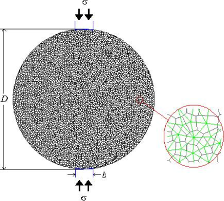
Cohesion between the elements is introduced in the model by the inclusion of beams between neighboring polygons, see Fig. 1. The use of beams, as opposed to simple springs, takes into account tension and bending deformations, which are especially important in the complex multi-axis stress field regime present in the geometries used experimentally. This model also resolves the local torques and shear forces which naturally arise when dealing with materials with complex micro-structures, where grains or aggregates are embedded in a matrix material. Beams have been particularly used in the literature to prevent an unphysical failure of the system under shear D’Addetta and Ramm (2006), which happens when using central force elements. A detailed description of the beam model is given elsewhere Herrmann et al. (1989b); Kun et al. (1999); D’Addetta et al. (2001). Briefly, the centers of mass of neighboring elements are connected by beams which can suffer stretching and bending deformation, and hence, exert an elastic force and torque on the polygons when stretched or bent Herrmann et al. (1989b); Herrmann and Roux (1990); Kun and Herrmann (1996a, 1999); Skjetne et al. (2001); Aström et al. (2004); Linna et al. (2005); D’Addetta and Ramm (2006); Alava et al. (2006); Aström (2006).
| Parameter | Value | |
|---|---|---|
| Number of elements | ||
| Density | ||
| Bulk Young modulus | ||
| Beam Young modulus | ||
| Time step | ||
| Diameter of the disk | ||
| Typical size of a single element | ||
| Width of the load platen | ||
| Memory factor | ||
| Range of memory |
In the model beams can break according to specified rules in order to explicitly model damage, fracture and failure of the solid Kun et al. (1999); D’Addetta et al. (2001). The imposed breaking rule must take into account both the immediate breaking of the beams by stretching and bending, as well as the accumulation of damage and the healing mechanism. In order to achieve these conditions for each beam, at time , we evaluate the quantities and defined by
| (1a) | ||||
| (1b) | ||||
where is the longitudinal deformation of the beam, and and are the rotation angles at the ends of beams between sites and , respectively. Equation (1a) has the form of the von Mises plasticity criterion describing the mechanical strength of beams with respect to stretching and bending deformation. The first part of Eq. (1a) refers to the breaking of the beam through stretching and the second through bending, with and being the threshold values for elongation and bending, respectively. Equation (1b) refers to the long term memory, and accounts for the accumulation of damage and the healing mechanism. The rate of damage accumulation is assumed to have the form , i.e. the damage accumulated until time is obtained as an integral over the loading history of elements . In our model healing is captured such that microcracks nucleated in beams can recover, a process which limits the total amount of damage. We describe this effect by introducing a finite range of memory over which the load experienced by beams has a contribution to the damage. For polymeric materials the dynamics of long chain molecules typically lead to an exponential form of the healing term. In Eq. (1b) the parameter is a memory factor and is the time range of the memory over which the loading history of the specimen contributes to the accumulation of damage Herrmann et al. (1989a), and therefore a parameter that controls the healing mechanism. The breaking condition Eqs. (1a) and (1b) are evaluated at each iteration time step and those beams for which are considered to be broken, i.e., are removed from the simulation.
For simplicity, all the beams have the same threshold values and , and disorder is introduced in the model solely through the mesh generation Kun and Herrmann (1996a, b, 1999); Kun et al. (1999); D’Addetta et al. (2001); D’Addetta (2004). The global material properties can be tuned by adjusting geometrical and microscopic physical parameters of the model. The randomness of the Voronoi tessellation and the average size of the mesoscopic elements, which define the average length and width of the beams are geometrical parameters that, together with the Young modulus of polygons and that of the beams determine the macroscopic response of the model material Kun and Herrmann (1996a, b, 1999); Kun et al. (1999); D’Addetta et al. (2001); Behera et al. (2005). The time evolution of the system is calculated by numerically solving the equations of motion for the translation and rotation of all elements using a sixth-order predictor-corrector algorithm. The breaking rule is evaluated at each iteration step. The breaking of beams is irreversible, which means that it is excluded from the force calculations for all following time steps. Table 1 summarizes the parameter values used in the simulations.
Since usually the fracturing of materials is highly dependent on the structural environment in which it is studied, one needs to reproduce the experimental geometry as accurately as possible. Starting from the Voronoi construction of a square, one cuts a disk-shaped specimen by removing those polygons outside the disk region and reshaping those at the border. The loading conditions for the numerical specimen are shown in Fig. 1. This specimen is loaded in diametral compression by non-deformable platens, which are modeled by introducing two new polygons with the same physical properties of the loaded material. The load platens are cut with the same curvature of the disk. The ratio between the width of the load platen and the diameter of the disk is , as in the experiments of Ref. Kun et al. (2006). In the simulations presented in this paper each disk specimen is composed of 5070 mesoscopic elements.
III Results and Discussion
III.1 Fracture development
In the numerical experiments the sample is loaded with a constant external stress . In order to avoid undesirable large elastic waves, the load applied to the opposite platens is slowly increased from zero. When the load reaches the value , the numerical sample is allowed to equilibrate during thousands of time steps including a small damping between the grains and friction according to Coulomb’s friction law D’Addetta et al. (2001); Kun et al. (1999).
Only after equilibration the breaking rules are applied to the beams. With this slow loading and long equilibration time, the vibrations of the sample are drastically reduced compared to the case when a constant load is applied instantaneously to the platens. The parameter values used in the simulations are summarized in Table 1.
First we carried out computer simulations in order to determine the quasi-static strength of the model solid at the given parameters. Then the damage and fracture of the disc was studied varying the external load below . In order to understand the failure process we studied in details the evolution of the crack pattern during the simulations. Figure 2 presents snapshots of the evolving system for a disk of diameter 20 cm (approximately 80 polygons) and . In the initial stage of fracture, shown in Fig. 2(a), a number of cracks appears in the regions situated near the border of the platens contacts. Because of the finite width of the platens, the stress field induced in the sample is not purely uniaxial tensile stress along the load direction as one might expect Tsoungui et al. (1999), so the cracks do not initiate from the middle of the specimen. In fact, the cracks initiate from the border and coalesce to form wedges, as shown in Figure 2(b). The wedges extend up to approximately , exhibiting a series of parallel vertical cracks, characteristic of compressive tests Kun et al. (1999). As time evolves the wedges penetrate the specimen (see Fig. 2(c)) originating a fracture in the center of the specimen, in a narrow region between the load platens. This mechanism leads to the sudden and catastrophic failure of the specimen (as shown in Figure 2 (d)). This failure behavior agrees qualitatively well with previous experimental observations Kun et al. (2006); Lilliu and van Mier (1999).
It is important to emphasize that without the time dependent damage accumulation, the system would not have macroscopic failure under a load . After some cracking events the disc would attain equilibrium resulting in an infinite lifetime. However, according to the failure criterion Eq. (1b), intact elements accumulate damage which results in beam breaking after a finite time even under a constant local load. These beam breakings due to damage accumulation give rise to load redistribution and stress enhancements on intact elements triggering additional breakings. In this way, if healing is neglected, or analogously is set in Eq. (1b), the system would fail after a finite time at any small load value. One can conclude from Eq. (1b) that the main role of the memory factor is to control the relevant time scale of the system, i.e. the lifetime of the specimen has a dependence .
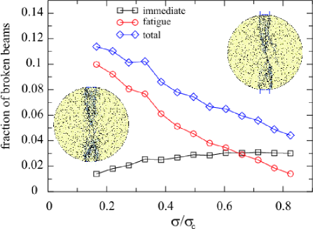
In order to analyze the importance of the accumulation of damage in the fracture process, we have investigated the final fractions of the beams that have been broken during the course of the simulations due to the immediate breaking rule (first term in Eq. (1b)) and those that have been broken due to damage accumulation (second term in Eq. (1b)) for different applied loads. Figure 3 shows the fractions of the broken beams due to the different breaking modes as a function of the applied load. For low load values damage dominates the failure of beams, while immediate breaking plays only a minor role. As the external load is increased, the fraction of broken beams due to damage accumulation decreases monotonically, while that due to immediate breaking increases and saturates. For the immediate breaking mode becomes dominant. It is interesting to note that the total fraction of broken elements is a decreasing function of the load, implying that correlated crack growth dominates when
One of the most important features of our modeling approach is that it accounts for the inhomogeneous stress field in the specimen and provides also information on the microstructure and spatial distribution of damage. The ageing of beams is less sensitive to the details of the stress field in the specimen. That is why when damage accumulation dominates the breaking of beams microcracks are more dispersed in the stripe of the specimen between the loading platens. The insets of Fig. 3 show the final fracture pattern corresponding to and . For (left), where the effect of fatigue is more important, we observe more disordered cracks, while for , where the immediate breaking process is more important, longer cracks can be identified due to crack growth.
In our model the importance of damage accumulation for the beam breaking is controlled by the memory factor with respect to the immediate failure of elements. Figure 4 demonstrates crack patterns obtained at the same load without healing varying the value of . It can be observed that for large values of , even at a relatively high load , a large amount of distributed cracking occurs in the specimen. Correlated crack growth can only be observed for low (see Fig. 4a) where immediate breaking has dominance. These crack patterns are very similar to those originated due to memory effects in thermal fuse networks Sornette and Vanneste (1992). The effect of increasing the memory factor resembles the effect of decreasing the applied load, in the sense that increasing has the same effect of enlarging the lifetime of the sample, as can be inferred from Eq. (1b).
III.2 Macroscopic time evolution
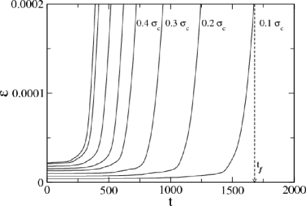
On the macroscopic level the time evolution of the system is characterized by the overall deformation of the disk and the lifetime of the specimen. The total deformation of the specimen, , is obtained directly from the simulation by monitoring the position of the loading platens. Figure 5 shows the behavior of as a function of time for different values of with respect to the tensile strength of the simulated specimen. Due to accumulation of damage, increases monotonically until catastrophic failure of the material occurs. Some fluctuations can be seen in before it starts increasing rapidly, due to the natural randomness of the beam breaking. The lifetime of the specimen is defined as the time at which the deformation diverges. It can be observed that, by increasing , the lifetime rapidly decreases and actually goes to zero as the external load approaches the tensile strength of the material .
For the purpose of fitting the experimental results, the most important parameters of the model that can be tuned are the two threshold values and for the stretching and bending deformation of the beams, as well as the memory factor and the range of memory . As we have pointed out, only sets the time scale of the system, while the other three parameters have a strong effect on the qualitative form of and .
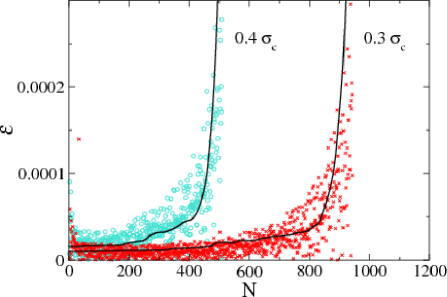
In the experiments of Ref. Kun et al. (2006) the asphalt specimen was subjected to periodic loading with a constant amplitude monitoring the maximum deformation as a function of the number of loading cycles and the number of cycles to failure. In our model a constant load or a periodic load with a constant amplitude would have the same effect, hence, we directly compare the simulation results to the experimental findings.
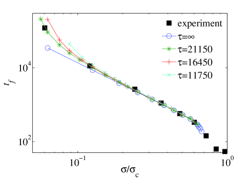
Figure 6 shows a fit of the experimental results of Ref. Kun et al. (2006) to the simulations, obtained by relating time to number of cycles and an appropriate choice of geometrical and physical parameters for the mesoscopic elements and beams. We see that the simulation and the experimental curves show excellent agreement.
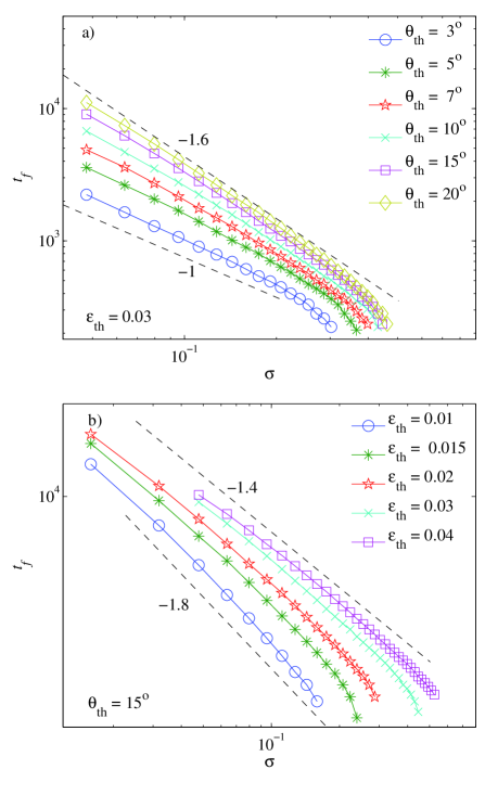
In order to examine the consequences of the predominance of stretching or bending breaking modes we performed a number of simulations with different threshold values. The dependence of the lifetime on the external applied load is shown in Figure 7, for and different values of and . The simulations show that for external loads , for all curves the lifetime decreases rapidly and approaches the immediate failure of the specimen. For intermediate values of applied load, exhibits a power law behavior, in accordance with the Basquin law of fatigue Basquin (1910)
| (2) |
where the value of the exponent can be controlled by the breaking parameters . We can see in Fig. 7a that for a fixed value of the Basquin exponent varies from for (bending breaking mode dominance) to as we increase to , hence increasing the influence of the stretching breaking mode. Obviously, the value of also increases with increasing , since one of the breaking modes gets completely suppressed. Similarly in Fig. 7b, with a fixed value of the Basquin exponent varies from for to for , in which case there is a clear predominance of the stretching breaking mode.
In order to obtain the measured value the breaking parameters had to be set such that the stretching mode of Eq. (1a) dominates the breaking, i.e. and were used which implies that the bending mode has only a minor role in breaking. The upturn of the curves of for small loads in Fig. 8 indicates the emergence of the fatigue limit in the system below which the specimen only suffers partial failure and has an infinite lifetime. Figure 8 also illustrates that the value of is determined by the range of memory , since healing has only a dominating effect on the time evolution of the system when is comparable to the lifetime of the specimen measured without healing (). Hence, it follows from the Basquin law, Eq.2, that the fatigue limit scales with as . The good quantitative agreement between simulations and experiment obtained for indicates that the stretching breaking mechanism is more important for this particular material. This is reasonable since the polymer binding in asphalt can not sustain torsion.
IV Conclusions
We carried out a computational study of the fatigue failure of disordered materials occurring under a constant external load. A two-dimensional discrete element model was extended to capture microscopic failure mechanisms relevant for the process of fatigue. As a specific example, we considered experiments on asphalt where damage recovery in the form of healing is known to play a crucial role for the long term performance of the material.
The breaking of beams is caused by two mechanisms: immediate breaking occurs when the failure thresholds of stretching and bending are exceeded. Intact beams undergo a damage accumulation process which is limited by the finite range of memory (healing). The relevant parameters of the model to fit the experimental results are the breaking thresholds of stretching and bending and the range of memory . We carried out a large amount of computer simulations to study the time evolution of the system at the macro- and micro-level. We demonstrated that at the micro-level failure of beams due to damage is responsible for the diffuse crack pattern, while correlated crack growth is obtained when immediate breaking has dominance. The model provides a good quantitative agreement with previous experimental findings on the fatigue failure of asphalt, i.e. varying only three parameters , , and of the model we could reproduce the deformation-time diagram and the Basquin-law of asphalt obtained in experiments. Very interestingly we found that the value of the Basquin exponent of the model is controlled by the relative importance of the stretching and bending modes in beam breaking. The fatigue limit is obtained as a threshold value of the external load below which the specimen does not suffer macroscopic failure and has an infinite lifetime. In the framework of our model is solely determined by the range memory over which local loads contribute to the total accumulated damage in the system.
V Acknowledgments
We thank the Brazilian agencies CNPq, FUNCAP and CAPES for financial support. H. J. Herrmann is grateful to Alexander von Humboldt Stiftung and for the Max Planck Prize. F. Kun was supported by OTKA M041537, and T049209.
References
- Alava et al. (2006) M. J. Alava, P. K. V. V. Nukala, and S. Zapperi, Adv. Phys. 55, 349?476 (2006).
- Herrmann and Roux (1990) H. J. Herrmann and S. Roux, eds., Statistical Models for the Fracture of Disordered Media (North-Holland, 1990).
- Shcherbakov and Turcotte (2003) R. Shcherbakov and D. L. Turcotte, Theor. Appl. Fract. Mec. pp. 245–258 (2003).
- Turcotte (1992) D. L. Turcotte, Fractals and Chaos in Geology and Geophysics (Cambridge Univ. Press, 1992).
- de Arcangelis et al. (1989) L. de Arcangelis, A. Hansen, H. J. Herrmann, and S. Roux, Phys. Rev. B 40, 877 (1989).
- Carpinteri and Pugno (2005) A. Carpinteri and N. Pugno, Nature Materials 4 (2005).
- Herrmann et al. (1989a) H. J. Herrmann, J. Kertész, and L. de Arcangelis, Europhys. Lett. 10, 147 (1989a).
- Matthews et al. (1993) J. M. Matthews, C. L. Monismith, and J. Craus, J. Transp. Eng.-ASCE 119, 634 (1993).
- Daniel and Kim (2001) J. S. Daniel and Y. R. Kim, J. Mater. Civil Eng. 13, 434 (2001).
- Zhiming et al. (2002) S. Zhiming, D. N. Little, and R. L. Lytton, J. Mater. Civil Eng. 14, 461 (2002).
- Kim et al. (2003) Y.-R. Kim, D. N. Little, and R. L. Lytton, J. Mater. Civil Eng. 15, 75 (2003).
- Lundstrom et al. (2004) R. Lundstrom, H. D. Benedetto, and U. Isacsson, J. Mater. Civil Eng. 16 (2004).
- Castro and Sánchez (2006) M. Castro and J. A. Sánchez, J. Transp. Eng.-ASCE 132, 168 (2006).
- Kun et al. (2006) F. Kun, M. H. S. Costa, R. N. C. Filho, J. S. A. Jr., J. B. Soares, S. Zapperi, and H. J. Herrmann, cond-mat/0607606 (2006).
- Basquin (1910) O. H. Basquin, in Am. Soc. Test. Mater. Proc. (1910), vol. 10, pp. 625–630.
- Sornette et al. (1992) D. Sornette, T. Magnin, and Y. Bréchet, Europhys. Lett. 20, 433 (1992).
- Lee et al. (1999) H. J. Lee, Y. R. Kim, and S. H. Kim, Struc. Eng. Mech. 7, 225 (1999).
- Kim and Little (2004) Y.-R. Kim and D. N. Little, J. Mater. Civil Eng. 16, 122 (2004).
- Kim et al. (1991) Y. R. Kim, D. N. Little, and R. C. Burghardt, J. Mat. Civil Engrg. 3, 140 (1991).
- Prager and Tirrel (1981) S. Prager and M. Tirrel, J. Chem. Phys. 75 (1981).
- Li and Metcalf (2002) Y. Q. Li and J. B. Metcalf, J. Mater. Civel Eng. 14, 303 (2002).
- Kun and Herrmann (1996a) F. Kun and H. J. Herrmann, Comput. Methods Appl. Mech. Engrg. 138, 3 (1996a).
- Kun and Herrmann (1996b) F. Kun and H. J. Herrmann, Int. J. Mod. Phys. C 7, 837 (1996b).
- Kun and Herrmann (1999) F. Kun and H. J. Herrmann, Phys. Rev. E 59, 2623 (1999).
- Kun et al. (1999) F. Kun, G. A. D’Addetta, H. J. Herrmann, and E. Ramm, Comp. Ass. Mech. Eng. Sci. 6, 385 (1999).
- Lilliu and van Mier (1999) G. Lilliu and J. van Mier, in H. W. Reinhardt 60 years (1999).
- Zhu and Tang (2006) W. C. Zhu and C. A. Tang, Int. J. Rock. Mech. Min. Sci. 43, 236 (2006).
- Brara et al. (2001) A. Brara, F. Camborde, J. Klepaczko, and C. Mariotti, Mech. Mater. 33, 33 (2001).
- Thornton et al. (2004) C. Thornton, M. T. Ciomocos, and M. J. Adams, Pow. Technol. 140, 258 (2004).
- van de Steen and ad J. A. L. Napier (2005) B. van de Steen and A. V. ad J. A. L. Napier, Int. J. Fract. 131, 35 (2005).
- Herrmann et al. (1989b) H. J. Herrmann, A. Hansen, and S. Roux, Phys. Rev. B 39, 637 (1989b).
- Skjetne et al. (2001) B. Skjetne, T. Helle, and A. Hansen, Phys. Rev. Lett. 87 (2001).
- Aström et al. (2004) J. A. Aström, R. P. Linna, J. Timonen, P. F. Moller, and L. Oddershede, Phys. Rev. E 70, 026104 (2004).
- Linna et al. (2005) R. P. Linna, J. A. Aström, and J. Timonen, Phys. Rev. E 72, 015601(R) (2005).
- D’Addetta and Ramm (2006) G.-A. D’Addetta and E. Ramm, Granular Matter 8, 159 (2006).
- Aström (2006) J. A. Aström, Adv. Phys. 55, 247?278 (2006).
- D’Addetta et al. (2001) G. D’Addetta, F. Kun, E. Ramm, and H. J. Herrmann, in Continuous and Discontinuous Modelling of Cohesive-Frictional Materials (Berlin: Springer, 2001), vol. 568 of Springer Lecture Notes in Physics, pp. 231–258.
- D’Addetta (2004) G. A. D’Addetta, Ph.D. thesis, Institut für Baustatik der Universität Stuttgart (2004).
- Behera et al. (2005) B. Behera, F. Kun, S. McNamara, and H. J. Herrmann, J. Phys.: Condens. Matter (2005).
- Tsoungui et al. (1999) O. Tsoungui, D. Vallet, J.-C. Charmet, and S. Roux, Gran. Matter 2, 19 (1999).
- Sornette and Vanneste (1992) D. Sornette and C. Vanneste, PRL 68, 612 (1992).