Exact solution for the dynamical decoupling of a qubit with telegraph noise
Abstract
We study the dissipative dynamics of a qubit that is afflicted by classical random telegraph noise and it is subject to dynamical decoupling. We derive exact formulas for the qubit dynamics at arbitrary working points in the limit of infinitely strong control pulses (bang-bang control) and we investigate in great detail the efficiency of the dynamical decoupling techniques both for Gaussian and non-Gaussian (slow) noise at qubit pure dephasing and at optimal point. We demonstrate that control sequences can be successfully implemented as diagnostic tools to infer spectral proprieties of a few fluctuators interacting with the qubit. The analysis is extended in order to include the effect of noise in the pulses and we give upper bounds on the noise levels that can be tolerated in the pulses while still achieving efficient dynamical decoupling performance.
pacs:
03.65.Yz, 03.67.Pp, 05.40.-aI Introduction
Small superconducting circuits containing Josephson junctions have received a great deal of attention recently as promising candidates for scalable quantum bits (qubits). Unfortunately, despite the last few years of remarkable experimental and theoretical breakthroughs Nakamura et al. (1999); Vion et al. (2002); Chiorescu et al. (2003); Wallraff et al. (2004); Martinis et al. (2002), neither of these circuits satisfies the requirement that the coherence times must be considerably longer than the gate operation times DiVincenzo (2000). Thus a major challenge for the next years is to achieve control of the decoherence afflicting these devices.
It is generally recognized that in superconducting qubits the main sources of noise are: the external circuitry, the motion of trapped vortices in the superconductors and the motion of background charges (BCs) in associated dielectrics and oxides. While the noise originating from the external circuitry can be reduced and practically eliminated by improving the circuit design and the motion of trapped vortices can be suppressed by making the superconductor films sufficiently narrow, it is currently not known how to suppress and control charge noise. Indeed, moving BCs of unknown origin are clearly responsible for the relatively short coherence time in the smaller Josephson charge qubits Nakamura et al. (1999). In addition, BCs limit the performances of the flux qubits Chiorescu et al. (2003), the phase qubits Martinis et al. (2002) and the hybrid charge-flux qubits Vion et al. (2002) because they induce fluctuations in the critical current of the Josephson junctions and lead to qubit dephasing.
It is firmly established now that in all superconducting qubits both the spectrum of charge noise and critical current fluctuations display a behavior at low frequencies. Specifically, charge noise spectra have been directly measured up to frequencies Hz Zimmerli et al. (1992); Visscher et al. (1995); Zorin et al. (1996); Vion et al. (2002); Nakamura et al. (1999); Martinis et al. (2002). The intensity of the noise varies in the small range and because its magnitude is greatly reduced by the echo techniques Nakamura et al. (2002); Ithier et al. (2005), it is commonly believed that noise does not extend above MHz. Similarly, it has been shown that critical current fluctuations display a behavior at Hz although very little is known at higher frequency Wel ; Wellstood et al. (2004); Harlingen et al. (2004).
Both charge noise and critical current fluctuations can be phenomenologically explained by modeling the environment as a collection of discrete bistable fluctuators, representing charged impurities hopping between different locations in the substrate or in the tunnel barrier. Because the hopping time is exponential in the height of the barrier separating different impurity states, one expects a wide distribution of the relaxation times for the fluctuators. Such wide distributions naturally lead to the low frequency dependence.
The discrete nature of the environment has important consequences for the qubit dephasing. As was shown in Ref. Paladino et al., 2002, the effect of a bath of fluctuators on the qubit is very different from that of a continuum of linearly coupled oscillator modes, which is the subject of the Caldeira-Leggett dissipation theory Leggett et al. (1987). The discreteness of the environment becomes especially important for the slow modes which switching rates that are longer or comparable to the operational time of the qubits. Qubit interaction with slow fluctuators might lead to non-Markovian errors that are difficult to correct Alfieri et al. (2005) and to a fast initial qubit dephasing Falci et al. (2005).
It has been recently suggested that dynamical decoupling techniques Viola and Lloyd (1998) could be very promising strategies for suppressing the noise generated by slow fluctuators in superconducting qubits Shiokawa and Lidar (2004); Gutmann et al. (2004a); Faoro and Viola (2004); Falci et al. (2004). Unfortunately, because the behavior of the charge noise power spectrum is known only in very limited interval of frequencies, it is still not obvious whether it is possible to develop efficient dynamical decoupling schemes for these devices.
Indeed, besides the low frequency part of the charge noise spectrum, so far it is only known that charge noise displays an ohmic behavior at very high frequencies () Astafiev et al. (2004). The noise spectrum at intermediate frequencies can only be inferred from its effects on the qubit and so its detailed behavior is not known. This missing part is very important for the development of dynamical decoupling techniques, because the presence of noise at the time scales corresponding to the time interval between echo pulses limits the error suppression capability of these techniques.
Interestingly, it has been argued that dynamical decoupling techniques might be also used to extract information on this missing part of the noise spectrum, as a sort of diagnostic tools to infer spectral proprieties of the charge fluctuators coupled to the qubitFaoro and Viola (2004); Falci et al. (2004). Several numerical results pointed out that the interplay between the applied pulses and the qubit dynamics might originate a rich behavior in the dissipative dynamics depending on the characteristics of the fluctuators and the working point of the qubit. This conjecture is supported also by a few analytical results. For example, in Ref. Faoro and Viola, 2004 the authors derived the analytical solution for the ideal (i.e. with no errors in the pulses) dynamical decoupling of a qubit coupled to many fluctuators at pure dephasing, while in Ref. Falci et al., 2004 the analytical solution for the ideal decoupling of a qubit coupled to a fluctuator at a generic working point has been sketched. However, we believe that from these analytic results it remains still difficult to estimate the effective diagnostic capabilities of the dynamical decoupling techniques. Moreover, in a realistic set-up, one should expect that the dynamical decoupling is not ideal and it should be desirable to extend this analysis to include errors in the pulses.
This paper aims (i) to simplify the previous analytical solutions of the dynamical decoupling at pure dephasing, (ii) to find the analytic solution of the dissipative qubit dynamics at the optimal working point, (iii) to extend these analytical results to the case of non-ideal control pulses. We hope that this novel approach and our analytical solutions might be relevant in the design and interpretation of new experiments.
A remark is needed at this point. In this paper we shall study only the dissipative dynamics of the qubit coupled to a single classical fluctuator that is subject to dynamical decoupling. There are several reasons for this choice. First, there are interesting experimental situations where there is evidence of a single fluctuator dominating the qubit dynamics Nakamura et al. (2002); Est ; Galperin et al. (2004). In this case, the analytical solutions derived in the following sections are sufficient to interpret the experimental data. Second, we believe that even from this simple solvable model one can obtain some important insights and intuitions on the slow frequency noise and especially on its non-Gaussian nature. Third, at pure dephasing, it is trivial to extend our analytical results to many fluctuators interacting with the qubit, because the total response is simply the linear combination of the contributions from each individual fluctuator Galperin et al. (2004).
On the other hand, the fact that we are considering a classical fluctuator implies that our discussion most likely will be relevant to superconducting qubits made out of a Cooper pair box or more generally to those superconducting circuits containing ultrasmall junctions (having area ) where the presence of few dominant classical fluctuators have been clearly observed in critical current fluctuations Wakai and Van Harlingen (1987); Rogers and Buhrman (1985).
However, it is relevant to mention here that also experiments in phase qubits Martinis et al. (2002); Lang et al. (2004) and very recently in flux qubits Nak show the presence of single charged impurities strongly coupled to the qubit and seriously affecting its dynamics. It would be very interesting to see whether dynamical decoupling sequences could help the characterization of the noise even in these cases. However, since it is reasonable to expect that those charged impurities are quantum Two Level Systems present in the insulating barrier of the Josephson junctions Faoro and Ioffe (2006), the analysis discussed here should be extended in order to take into account the quantum nature of the fluctuator. This will be the subject of future work.
This paper is organized as follows. In Sec. II we shall briefly recall the physics of the Cooper pair box, we shall derive the total Hamiltonian of the qubit in interaction with a bath of fluctuators and with applied an external control field and we shall finally explain how sequences of pulses can be generated in this device. In Sec. III we shall present analytical results for the dynamics of the qubit subjected to ideal dynamical decoupling (i.e. with no errors in the pulses) at different qubit working points. Specifically, in Subsec. III.1 we shall consider the qubit at pure dephasing and we shall greatly simplify the analytical result given in Ref. Faoro and Viola, 2004, thereby immediately elucidating the efficacy of the dynamical decoupling as a diagnostic tool. In Subsec. III.2 we shall provide the analytical solution for the dissipative dynamics of the qubit subjected to dynamical decoupling at the optimal point. This result will allow us to comment on the evidence of the anti-Zeno effect in this regime Faoro and Viola (2004); Falci et al. (2004) and to explain how the latter can be conveniently avoided. In Sec. IV we shall discuss dynamical decoupling sequences with imperfect pulses. The consequences of imperfect bang bang pulses have been already discussed, for the case of a single fluctuator, in Ref. Gutmann et al., 2004b. Here, by using our approach, we are able to derive bounds on the pulse noise that can be tolerated by the device while still achieving dynamical decoupling. Finally, Conclusions are discussed in Sec. V.
II Cooper pair box, charge noise and control
A Cooper pair box Nakamura et al. (1999); Vion et al. (2002) is a small superconducting island connected to a reservoir via two Josephson junctions (see Fig. 1).
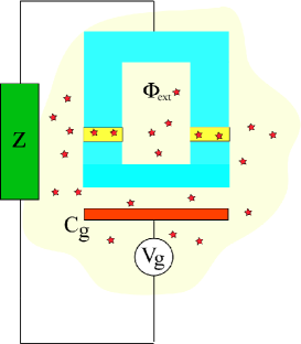
The box is characterized by two energies: the Josephson coupling energy and the charging energy . , are the Josephson energies and , are respectively the external magnetic flux piercing the superconducting loop and the flux quantum. is the total capacitance of the box and denotes the electron charge.
Under the assumptions that (i) the charging energy is much larger than the Josephson coupling , (ii) the superconducting gap of the box is larger than its charging energy (so to avoid quasi-particle excitations), (iii) the temperature is small compared to all these energy scales, it is possible to describe the dynamics of the Cooper pair box as a two state system, whose Hamiltonian in the charge basis reads:
| (1) |
where are the Pauli matrices. Both the bias and the Josephson energy can be easily tuned by varying, respectively, the applied gate voltage and the magnetic field threading the loop containing the island.
The Hamiltonian given in Eq. (1) describes the dynamics of an ideal Josephson charge qubit. However, it is known that many charged impurities are present in the amorphous materials both of the substrate (on which the Cooper pair box is grown) and of the Josephson barriers. These charges, by interacting with the qubit, are responsible for its decoherence.
In order to write an Hamiltonian for a realistic (with charge noise) Cooper pair box, one usually assumes that, irrespective of the exact microscopic nature, the charge impurities are charges that tunnel between two positions. Each charge is described as a quantum Two Level System (TLS) that is controlled by the Hamiltonian Anderson et al. (1972); Black and Halperin (1977); Burin (1995) :
| (2) |
Here is the energy difference between the two tunneling minima, is the tunneling amplitude and are the Pauli matrices acting on the impurity states. Each TLS is subject to dissipation due to its own bath with Hamiltonian . In this picture, the interaction between several charged impurities and the charge states of the Cooper pair box can be written as:
| (3) |
By adding Eqs. (1), (2) and (3), we finally obtain the Hamiltonian of a non-ideal (with charge noise) Josephson charge qubit.
Fortunately, experiments performed on Cooper pair boxes indicate that this rather complicated model of the charge noise can be simplified. In fact, it has been observed that charge impurities that are responsible for the low frequency noise behave essentially classical, i.e. they become equivalent to classical fluctuators each characterized by a switching rate and the coupling to the qubit . In this approximation the interacting Hamiltonian given in Eq. (3) simplifies to the following qubit-fluctuators Hamiltonian:
| (4) |
and the quantum TLS dynamics given in Eq. (2) is substituted by the classical noise , representing a symmetric Random Telegraph Process (RTP) switching between values with rate Joa . If we assume a distribution at for the switching rates, we find for the total noise acting on the qubit a spectrum , , with coefficient proportional to the number of fluctuators per noise decade and their typical coupling to the qubit Dutta and Horn (1981); Weissman (1988). Note that we assume the switchings to be symmetric, that is, we assume the switching rate from the upper to the lower and from the lower to the upper TLS state to be the same. This is valid if the temperature is larger than the TSL level spacing so that there is no population difference between the two states. This restriction can be relaxed Paladino et al. (2002) but for simplicity we shall work in the symmetric (high temperature) limit.
Therefore, in this classical picture, the realistic Hamiltonian of a Cooper pair box afflicted by charge noise, is given by the sum of Eq. (1) and Eq. (4). In the qubit eigenstates, we find that:
| (5) |
where , defines the qubit working point and are the Pauli matrices in the rotated basis.
The state of the qubit given in Eq. (5) can be interpreted as the state of a pseudospin in a static magnetic field along with noise both in the and directions. Manipulations of the Cooper pair box state can be then achieved by applying an electromagnetic field which rotates in the plane at frequency , at or near the pseudospin precession frequency Collin et al. (2004). Given the Hamiltonian of the control radio-frequency (RF) field as follows:
| (6) |
where is the phase of the RF field and is the amplitude, the total Hamiltonian of the Josephson charge qubit with charge noise and applied control field reads (in the rotating frame):
In superconducting qubits typical values for the energy splitting are Ghz while the amplitude of the applied RF field might extend up to 250 MHz.
Different pulses sequences can be then generated by modulating the amplitude in Eq. (II). Specifically, usual dynamical decoupling sequences Viola and Lloyd (1998) are realized first by setting:
where is the number of pulses, is the length of each pulse, denotes the Heaviside step function and is the time interval between each pulse. Then, by choosing different values for the constant and the phase . For example, rotations by around the or axes, and pulses, are achieved by fixing and by setting respectively and . Notice that, the so called bang-bang control, characterized by pulses that are infinitely short and strong so that there is no qubit dynamics during the time of the pulse, is achieved in the limit for fixed value of the constant . In this paper we always consider only this limiting case.
III Ideal dynamical decoupling: exact solutions
In this section we solve analytically the dynamics of a Cooper pair box coupled to a single fluctuator and subject to ideal (i.e. without errors in the pulses) dynamical decoupling both at pure dephasing and at the optimal working point for the qubit.
The analytical solutions are derived by following the reasoning given in Ref. Bergli et al., 2006. The starting point is the Hamiltonian given in Eq. (5) that describes a qubit in interaction with a single fluctuator. The charge noise is then given by , where is the coupling strength of the fluctuator and denotes a symmetric RTP characterized by the switching rate .
It may be useful to recall here that in general, depending on the ratio between and , we can distinguish between two different types of fluctuators: those characterized by (named weakly coupled or Gaussian fluctuators), and those with (named strongly coupled fluctuators) that are responsible for the non-Gaussian features of the noise Paladino et al. (2003). The effect on the qubit dynamics of weak and strong fluctuators is dramatically different. In fact, while the weak fluctuators are fast and produce essentially the same effects on the qubit as a bath of harmonic oscillators, thereby leading to the exponential decay of the coherent qubit oscillations at long times, the strongly coupled fluctuators, being slow, are responsible for memory effects in the qubit dynamics, for a fast initial decoherence of the qubit signal and for the inhomogeneous broadening of the qubit spectrum.
Due to the time dependence of the noise generated by the fluctuator, the Cooper pair box behaves as a pseudospin in a variable magnetic field. Therefore, solving its dissipative dynamics is a nontrivial task. Fortunately, because of the bistable nature of the fluctuator, the problem can be simplified. In fact, at different times, depending on the state of the fluctuator, the qubit vector state precesses on the Bloch sphere around one of the two effective static magnetic fields: . As a result, a convenient strategy to study the decoherence of the qubit is following the evolution of the state vector on the Bloch sphere. In this picture, solving the dissipative dynamics of the qubit reduce to calculating the probability that at time the state vector reaches a point on the sphere.
III.1 Dynamical decoupling at pure dephasing.
At pure dephasing, , the analytic solutions for the dephasing rate of a qubit interacting with a single fluctuator are well known both in the case of free induction decay Paladino et al. (2003); Galperin et al. (2004); Bergli et al. (2006) and when sequences of pulses are applied to the qubit Faoro and Viola (2004); Falci et al. (2004). Here we derive these results by using a different approach that allows us (i) to simplify greatly the previous analytical solutions, (ii) to elucidate better the diagnostic capability of the dynamical decoupling and finally (iii) to suggest an easy experiment that might be performed in order to extract information on the microscopic nature of the fluctuator.
At pure dephasing the qubit acquires an extra random phase shift due to the interaction with the fluctuator. The dephasing rate is then given by the decay rate of the average value:
| (8) |
In order to evaluate it, we need to calculate the probability distribution .
Let us first introduce the small time steps and discretize the time integral given in Eq. (8). The random phase shift can be written as , where and the integration over time can be thought of as random walk process, where at each time step the random walker moves a step in a direction depending on the current position of the fluctuator.
To first order in , the probability that the fluctuator does not switch, i.e. that the next step is made in the same direction as the previous one, is given by . Similarly, is the probability that one switch occurs, i.e. that the step is made in the opposite direction of the previous one. Higher numbers of switches are negligible to the first order.
Let us denote by the number of steps from the origin (i.e. the position of the random walker is ) and by the number of temporal steps (i.e. the dimensional time is ). Let us calculate the discretized probability that the random walker reaches the position at time step . It is useful to introduce the probabilities and for the random walker to reach respectively the position coming from the left and from the right. These probabilities satisfy the following master equations:
| (9) |
and are such that .
In the limit of infinitesimal steps , these probabilities reduce to:
Accordingly, the master equations given in Eqs. (9) can be written as:
| (10) |
where we have introduced the matrix:
| (11) |
and we have defined: .
The solutions of Eqs. (10) can be easily guessed as and we get the following dispersion equation:
| (12) |
where the matrix
| (13) |
has the following eigenvalues:
| (14) |
and corresponding normalized eigenvectors:
| (15) |
It follows that the general solution to Eq. (10) reads:
| (16) | |||||
where the constants are determined by the initial conditions:
| (17) |
or, by using a more compact notation, .
By introducing the matrices:
| (18) |
we can conveniently write Eq. (16) as follows:
| (19) |
where . Then, by substituting Eq. (19) into Eq. (8), we finally find that the average phase shift reads:
| (20) | |||||
In order to evaluate the dephasing rate , it is convenient to expand the vector in terms of the eigenvectors of . It is then a matter of simple algebra to find that the resulting decay of the average phase shift given in Eq. (20) is indeed given by the sum of two exponentials with coefficients , where
| (21) |
are the eigenvalues of the matrix and we define .
The long time decay is given by the component that decays slower, i.e. the one that corresponds to the larger eigenvalue
| (22) |
This result agrees with the one given in Refs. Paladino et al. (2003); Galperin et al. (2004); Bergli et al. (2006).
A similar approach can be used in order to evaluate the dephasing rate of the qubit that is subject to dynamical decoupling. In particular, let us assume that we apply to the qubit a sequence of pulses. It is easy to realize that the effect of each pulse is simply to interchange the constants and . As a result, when a sequence of pulses is applied, the probability given in Eq. (19) reduces to:
| (23) |
where:
| (24) |
and is the total time.
Once this probability is known, it is straightforward to evaluate first the average phase shift acquired by the qubit:
and then the corresponding dephasing rate:
| (26) |
Here are the eigenvalues of . Depending on the nature of the fluctuator (i.e. weak or strong), the eigenvalues can be written as a function both of the fluctuator and the control parameters.
Let us first consider that the fluctuator coupled to the qubit is weak, i.e. . We find that:
| (27) |
Since the eigenvalue is the maximum one for each choice of the parameters, we find that the dephasing rate is given by:
| (28) |
In particular, to the lowest order in we find that:
| (29) |
From this simple analytical result, it is evident that in order to achieve an efficient suppression of the noise generated by a weak fluctuator we need to choose the time interval between two pulses . Namely, the efficiency of the dynamical decoupling is related to the switching rate of the weak fluctuator.
In Fig. 2 we plot given in Eq. (29) and we compare our analytic solution with the result of a numerical simulation where the time evolution of the qubit was followed for a given realization of the fluctuator RTP and averages taken over many such realizations. Numerical and analytical results are in good agreement. Moreover, as one should expect, by reducing the time interval between the pulses, the dephasing rate vanishes.
Let us now consider the case of a strongly coupled fluctuator. For , the constant becomes complex () and we find that the eigenvalues read now:
| (30) |
Differently from the expressions given in Eqs. (27), here the two eigenvalues are oscillating in the time interval between the pulses. It follows that there are two relevant dephasing times now:
| (31) |
To the lowest order in , we find that:
| (32) |
Notice that, by looking at Eq. (32), it is quite straightforward to realize that for the case of strong fluctuator an efficient suppression of the noise is achieved by setting . Therefore, the efficiency of the dynamical decoupling is related to the coupling strength of the strong fluctuator.
As evidenced by Fig. 3, the results of the numerical simulations clearly show that, depending on the time interval between the pulses, the dephasing rate of the qubit is dominated differently by the two dephasing rates .
In order to understand this behavior it is useful to write the average phase shift given in Eq. (III.1) as follows:
| (33) |
where we have introduced the weights . These can be calculated as follows. First, we write the initial state , given in Eq. (17), as a linear superposition of the eigenvectors of the matrix :
Then, we solve the following linear system of equations in order to find the coefficients :
| (34) |
For example, in the numerical simulations shown in Fig. 3, the fluctuator was initially assumed at equilibrium, i.e. . By following the above procedure, we find that the weights read:
| (35) |
In particular, to the lowest order in , we obtain that and we can immediately explain the oscillating behavior displayed in Fig. 3.
An important consideration is relevant at this point. By comparing Fig. 2 and Fig. 3 it is immediate to realize that the two plots are qualitatively different. One can then exploit this difference in order to distinguish between a weak and a strong fluctuator coupled to the qubit. For example, in an experiment, once a single flucutator has been singled out in a device, one could measure systematically the dephasing time of the qubit after cycles of pulses characterized by different times and observe if there is an oscillatory or not behavior in the data. The efficiency of the dynamical decoupling will then provide further information respectively on the coupling strength of the fluctuator or its switching rate .
However, in order to characterize completely the fluctuator both the two parameters and must be known.
III.2 Dynamical decoupling at the optimal point.
In this section we study the dissipative dynamics of a Cooper pair box tuned at the optimal point, i.e. , that is subject to control sequences of pulses. By using a similar approach to the one discussed in the previous section, we find the analytic solution for the qubit decoherence rate.
Contrary to the case of pure dephasing, at the optimal point the performance of the dynamical decoupling depends both on the characteristics of the charged fluctuators coupled to the qubit and on the qubit energy level splitting. In particular, quite worryingly, it has been noticed that the qubit decoherence can be even accelerated if the cycle time of the control is long with respect to the period of the free evolution of the qubit Faoro and Viola (2004); Falci et al. (2004). This acceleration is sometimes referred in the literature as the anti-Zeno effect Kofman and Kurizki (2000).
In the following we shall see indeed that this acceleration appears only when sequences of pulses are used to flip the qubit state and can be conveniently avoided by flipping the state with pulses.
To this aim, let us introduce the time evolution operator , where is the time dependent Hamiltonian given in Eq. (5) and let us study the time evolution of the qubit when a cycle of and pulses is applied to it. Let be the time interval between the pulses and let us consider first the case of pure dephasing.
Since the time evolution operator depends only on the qubit operator , at pure dephasing we see that the noise coming from fluctuators that are static during the time interval can be completely eliminated either by applying a cycle of or pulses. In fact, mathematically we obtain that:
| (36) |
where is the identity.
On the contrary, at the optimal point, the evolution operator depends both on the qubit operator (because of the interaction with the fluctuators) and (because of the Josephson coupling energy ). Mathematically we find that:
| (37) |
Namely, only by flipping the qubit state around the -axis we can completely suppress the noise due to fluctuators that are static in the time interval . Therefore, at the optimal point, the performance of the dynamical decoupling changes remarkably depending whether sequences of or pulses are used to decouple the qubit.
These considerations are clearly illustrated in Fig. 4 and Fig. 5. In Fig. 4 we study numerically the dissipative dynamics of a Cooper pair box that is coupled to a weak fluctuator. The qubit dephasing rate is displayed as a function of the time interval between cycles of pulses (upper Panel) and pulses (lower Panel).
Notice that only when pulses are applied to the qubit, the dephasing rate is monotonously reduced as the flipping rate is increased. On the contrary, for sequences of pulses, there are values of where the dephasing rate increases remarkably as compared to the rate when there are no control-flips (i.e. anti-Zeno effect Faoro and Viola (2004); Falci et al. (2004)).
A similar analysis is performed in Fig. 5 where the dissipative dynamics of the qubit coupled to a strong fluctuator is illustrated. Again, we find that the dephasing rate displays both the anti-Zeno effect and rapid oscillations when sequences of pulses are applied to the qubit (lower Panel). However, both the the acceleration and the oscillations disappear when control sequences of pulses are instead used (upper Panel).
Note that when control sequences of pulses are used both in Fig. 4 and Fig. 5 the efficiency of the dynamical decoupling is related to the qubit energy scale . In this case, in fact we need to choose time interval in order to obtain an efficient suppression of the noise due to the fluctuator. For sequences of pulses the efficiency of the dynamical decoupling is determined either by the switching rate (if ) or energy scale (if ) for the weak fluctuator and by ) for the strong fluctuator. This will be discussed after we have derived the analytic expressions below.
As a final remark, let us notice that the different performances of sequences of and pulses can be easily explained in the context of effective Hamiltonian theory Vandersypen and Chuang (2005), by stating that while -pulses provides decoupling only to the first order in the Magnus expansion of the dephasing rate, -pulses gives exact decoupling to all orders.
Having clarified this point, let us now proceed to derive the analytical solution for the dissipative dynamics of the qubit at optimal point. In view of the above considerations, in the following we shall only consider control sequences of pulses.
The analytical solution is derived by following the same reasoning discussed in the previous section. Here, the main difference is that the two effective static magnetic fields around which the state of the Cooper pair box precesses read now: . As a consequence, at the optimal point, the qubit does not acquire only a simple random phase due to the interaction with the charged fluctuator, but its state will spread over the entire Bloch sphere.
In order to calculate the probability that the qubit vector-state reaches the point on the Bloch sphere at a certain time , first we split the probability and then we derive the master equations for and :
| (38) |
where is the probability for the fluctuator to remain in the same state at the time while denotes the probability that it switches. Notice that in Eqs. (38) we have introduced the operator , where and the rotation matrices are defined as follows:
By performing the continuous limit , from Eqs. (38) we obtain directly the equations governing the time evolution of the Cooper pair box before the first pulse is applied:
| (39) |
In this picture to apply a pulse to the qubit simply means to reverse the effective magnetic field. As a result, given Eqs. (39), it is immediate to write the equations describing the time evolution of the state of the Cooper pair box after the application of the first pulse:
| (40) |
Clearly, once the second pulse is applied, the dissipative dynamics of the box is again described by the set of equations given in Eqs. (39) and so on for all the control cycles. Still we need to understand how to match the solutions just before and after the application of each pulse.
Let be the solutions of Eqs. (39) just before the first pulse, while are the solutions just after the pulse. Notice that the latter are indeed initial conditions for Eqs. (40). It is then easy to realize that a rotation around the -axis leads to the following matching conditions:
| (41) |
Therefore, we can write explicitly Eqs. (40) as follows:
| (42) |
where .
In order to solve them, it is useful to define the following expectation values:
| (43) |
We can then write Eqs. (42) in terms of Eqs. (43) and we obtain the following set of equations
| (44) |
having constant coefficients. Moreover, by introducing the variables , and , Eqs. (44) can be further reduced into the following two independent sets of equations:
| (45) |
and
| (46) |
Finally, by solving the system of Eqs. (45), we can estimate the dephasing rate . To this aim, it is sufficient to prepare the system in an equal superposition of eigenstates, i.e. with , and then to study the decay of the and components of the Bloch vector. Namely, we need to derive the decaying behavior of the variables and .
It is convenient to write the system of Eqs. (45) in matrix form:
| (47) |
where the matrix reads:
| (48) |
After a pulse is applied to the qubit, the matrix is replaced by the following matrix:
| (49) |
By resorting to Eqs. (41), it is straightforward to see that the evolution of the qubit state after one full control cycle can be described by the operator:
| (50) |
where we introduced the matrix
Eq. (50) can be further simplified to:
| (51) |
where we defined the matrix . Finally we find that, after an echo cycle:
| (52) |
where
| (53) |
and are the eigenvalues of the matrix . It follows that the dissipative dynamics of the qubit tuned at the optimal point is controlled by three different dephasing rates.
Let us now discuss the decay rates in the limiting cases of weak () and strong () fluctuator. In both cases, it can be proved that in Eq. (52) the weight . As a result, only the two dephasing rates and are relevant for the qubit dissipative dynamics.
Let us first evaluate them for the case of a weak fluctuator. After some calculations we find that:
| (54) |
| (55) |
Both from Eq. (54) and Eq. (55) it is evident that, contrary to the case of pure dephasing, the energy level splitting of the qubit plays now a major role in the dissipative dynamics of the qubit.
In order to understand the efficiency of the dynamical decoupling, it is useful to discuss the dephasing rates in two limiting case.
(i) weak fluctuator with .
In this case Eq. (54) and Eq. (55) reduce to:
| (56) | |||||
From Eq. (56) it is evident that in order to achieve an efficient suppression of the noise induced by the fluctuator we need to apply sequences of pulses with time interval between the pulses such that . Once this constrain is satisfied, we find that . Since this represents a negligible term, the decay of the Cooper pair box is effectively dominated by the decay rate .
As an illustrative example, in Fig. 6 we consider the dissipative dynamics of a qubit that is coupled to a fluctuator in this regime and we compare the exact solutions given in Eq. (54) and Eq. (55) to the numerics. Notice that for small time interval the dissipative dynamics is governed by the larger decay rate, presumably because larger weight is given to this solution.
(ii) weak fluctuator with .
In this limit, Eq. (54) and Eq. (55) become:
| (57) |
The efficiency of the dynamical decoupling can be easily inferred from the decaying rate given in Eq. (57) and, as in the previous case, the condition to satisfy is: . By expanding in the limit we obtain that . It follows that in order to keep the latter negligible one has also to satisfy the condition . As a result, in this limit, one should choose as condition for the efficient decoupling the strongest one, i.e. . This behavior is illustrated in Fig 7.
Let us now consider the case of a strong fluctuator coupled to the qubit. The dephasing rates read now:
| (58) | |||||
where . Since we are only considering noise that is weak compared to the level splitting of the qubit, , and the fluctuator is strong, i.e. , only the case is relevant. In order to have efficient dynamical decoupling of it is immediate to realize that we need to set . Once this constrained is satisfied, we find that . Therefore the dissipative dynamics is finally dominated by . An example is shown in Fig. 8.
IV Imperfect pulses.
So far we have assumed that the control pulses are ideal. Namely, they are zero-width pulses applied exactly along the or axis of the Boch sphere. However, in real applications it is plausible that the duration of the pulses exhibits random fluctuations, leading to error in the rotation angle and that the effective rotation axis might be deviated from the or axis.
Clearly, if the pulses are imperfect and the repetition rate between the control cycles is high, there is the possibility that the dynamical decoupling introduces more dephasing than what it is effectively capable to remove. As a result, given the noise characteristics of both the environment and the control pulses, there must exist an optimal pulse rate that sets the best decoupling performance. This section aims to determine this optimal pulse rate.
Control sequences with imperfect pulses have been already considered in two recent works Khodjasteh and Lidar (2005); Gutmann et al. (2004b). Our analysis differs from the previous studies because: (i) it takes into account the qubit dynamics between the control pulses; (ii) by using the analytic solutions derived in the previous sections, we are able to provide bounds on the amount of noise that can be tolerated in the pulses while still achieving efficient decoupling.
In order to calculate the optimal pulse rate it is convenient to proceed by steps. First we study the dissipative dynamics for an ideal qubit (without charge noise) that is dynamically decoupled with control sequences of noisy pulses, then we extend this analysis to a qubit afflicted by a charge fluctuator.
IV.1 Dephasing due only to errors in the pulses
In this section we study the dissipative dynamics of an ideal qubit that is subject to dynamical decoupling with noise in the pulses. Specifically, we assume that the effective rotation realized by each pulse fluctuates around the expected values: i.e. , where is a random variable.
In the absence of a fluctuator the time evolution of the vector state on the Bloch sphere from the end of one pulse to the end of next pulse is then given by
After pulses, we find that the total time evolution reads: . Let us now assume that the fluctuations () are uncorrelated and that they are Gaussian distributed. The average time evolution can then be easily calculated as and the decay rate of the qubit can be inferred by evaluating the eigenvalues of . Both for the case of pure dephasing and at the optimal point we find that, in the limit , the eigenvalues are:
where and at pure dephasing and at qubit optimal point.
It follows that, to the lowest order in , the dissipative dynamic of the qubit is controlled by three possible decaying rates for . Precisely we find that:
| (59) | |||||
| (60) |
At long times we expect that the qubit decay is controlled by the largest dephasing rate given in Eq. (59).
At small times, the controlled dissipative dynamics is more complicated. In order to understand it, we consider the case of a qubit that is tuned at pure dephasing and it is subject to sequences of pulses with fluctuating noise uniformly distributed. We solve numerically the dissipative dynamics for two different initial preparation of the qubit: either the qubit initial state is prepared along the -axis or the -axis of the Bloch sphere. The results of our simulations are illustrated in Fig. 9.
Notice that, depending on the initial conditions, the dissipative dynamics is dominated by different dephasing rates. For a qubit initially prepared along the -axis (-axis) of the Bloch sphere the dynamics is dominated by the dephasing rate (). In order to understand this, we need to evaluate the weights of the different components.
Let us indicate with the initial qubit vector state. It is convenient to write it as a linear combination of the eigenvectors of the average operator describing the evolution of the qubit vector state on the Bloch sphere during a control cycle, i.e. , with . After control cycles, the qubit vector state reads: and the coefficient can be easily found.
In the considered example, when the qubit is initially prepared along the -axis of the Bloch sphere, i.e. , we find that the coefficients reads: and . Therefore we understand immediately why in Fig. 9 the dephasing rate never dominates the dissipative dynamics. Moreover it is clear that, according to the oscillatory behavior of the coefficient displayed in the inset, the dissipative qubit dynamics at different time intervals between the control pulses is alternatively dominated by the two dephasing rates .
Notice that, in a realistic situation where dynamical decoupling sequences are introduced in the protocol during the computation, we might not know exactly which is the effective state of the qubit. As a result, from the point of view of the efficiency of the control when fluctuating noise in the pulses is considered, it is reasonable to assume that the dissipation is always given by the largest decay rate at all interval times between the pulses.
IV.2 Dephasing due to error in the pulses and fluctuator noise
Let us now consider that during the dynamical decoupling there is both noise coming from the pulses and a charge fluctuator that is coupled to the Cooper pair box. Since the two sources of noise are independent, we expect that the relaxation rates will just add. We could not prove this conjecture analytically, but results of numerical simulations clearly demonstrate that this is always the case.
As an example, in Fig. 10 we illustrate the dissipative dynamics of a qubit that is coupled to a weak fluctuator at pure dephasing. In the figure we plot: the analytic solution for the dissipative dynamics when there is noise only in the pulses given in Eq. (59) (green), the analytic solution for the dephasing rate due to the interaction of a weak fluctuator derived in Eq. (29) (blue) and the total dephasing rate resulting from the sum of the two (black). Notice that there is a good agreement between numerics and analytic results.
By looking at Fig. 10 we see that, by decreasing the time interval between the pulses, the dephasing rate initially decreases, then at a particular value of it reaches a pronounced minimum where the best dynamical decoupling performance is achieved and finally, by further decreasing , the performance of the decoupling deteriorates. Since the efficiency of the decoupling (i.e. the value of the minimum) is related to the level of noise in the pulses, it might be interesting to estimate how much noise in the pulses can be tolerated in order to have an efficient suppression of the noise due to the fluctuator.
To this aim, one has to find the time interval between the pulses when dynamical decoupling starts to reduce the decoherence rate. If the decoherence rate because of the noise on the flips () at this pulse rate is small compared to the one from fluctuators (which will be of the order of the rate without dynamical decoupling) there will be a range of below this point where dynamical decoupling is working, and it will not be destroyed by the pulse noise.
In Sec. III we have demonstrated that, depending on the nature of the fluctuator, efficient dynamical decoupling is achieved for if the fluctuator is weakly coupled to the qubit and for if the fluctuator is non-Gaussian. As a consequence, depending on the type of fluctuator interacting with the qubit, we find that the control sequences are efficient when the noise in the pulses satisfy the following conditions:
Notice that the noise tolerated in the pulses is bounded by the second power of the ratio for a weak fluctuator and only by the first power of for a non Gaussian fluctuator. Therefore, in a qubit afflicted by a strong fluctuator, efficient dynamical decoupling can be achieved with higher noise in the pulses.
A similar analysis can be done for a qubit that is tuned at the optimal point. Using the analytic solutions given in Sec. III.2 we find that an efficient dynamical decoupling can be achieved
-
-
For weak fluctuator, i.e. , when:
-
-
For strong fluctuator, i.e , when:
V Conclusions.
In this paper we studied the dissipative dynamics of a Cooper pair box (qubit) afflicted by charge noise that is dynamically decoupled. By focusing on the case where a single fluctuator is coupled to the qubit, we investigated the efficiency of ideal (without errors in the pulses) decoupling sequences. At qubit pure dephasing, irrespective of whether one applies sequences of or pulses, we found that the efficiency of the decoupling is strongly dependent on the characteristics of the fluctuator. For the case of a weak (Gaussian) fluctuator an efficient suppression of the noise is achieved by choosing the time interval between the pulse less than the switching rate of the fluctuator, while for a strong (non-Gaussian) fluctuator the relevant decoupling rate is determined by the coupling strength of the fluctuator to the qubit. As a result, in this limit dynamical decoupling techniques can be successfully implemented as a diagnostic tool to infer spectral informations on the nature of the fluctuator coupled to the qubit.
A different situation is encountered at the qubit optimal point, where we showed that the decoupling performance varies considerably depending whether control sequences of or pulses are used to decouple the qubit. Both for the case of weak and strong fluctuator we found that the dissipative dynamics is dominated by the qubit energy scale. Although for the special case of weak fluctuator characterized by a switching rate greater than the qubit energy level splitting we observed that the efficiency of the dynamical decoupling is achieved by choosing time interval between the pulses less than the switching rate of the fluctuator.
We have extended this analysis in order to include also errors in the pulses. We showed that, depending on the characteristic of the fluctuator and the error in the pulses, there must exist an optimal pulse rate that sets the best decoupling performance. Using the analytic solutions for the dissipative qubit dynamics derived both at pure dephasing and at the optimal point, we found upper bounds on the level of noise present in the pulses that can be tolerated while still achieving an efficient dynamical decoupling.
We believe that an interesting future research direction is to extend this analysis in order to take into account the quantum nature of the fluctuator. It would be extremely interesting to see whether dynamical decoupling techniques could be useful in order to understand the microscopic mechanisms of relaxations at low Temperature of the quantum Two Level Systems present in the amorphous materials of the barrier and substrate.
Acknowledgements.
This work was supported by the National Security Agency (NSA) under Army Research Office (ARO) contract number W911NF-06-1-0208 and the Norwegian Research Council via a StorForsk program.References
- Nakamura et al. (1999) Y. Nakamura, Y. A. Pashkin, and J. S. Tsai, Nature (London) 398, 786 (1999).
- Vion et al. (2002) D. Vion, A. Aassime, A. Cottet, P. Joyez, H. Pothier, C. Urbina, D. Esteve, and M. H. Devoret, Science 296, 886 (2002).
- Chiorescu et al. (2003) I. Chiorescu, Y. Nakamura, C. J. P. M. Harmans, and J. E. Mooij, Science 299, 1869 (2003).
- Wallraff et al. (2004) A. Wallraff, D. I. Schuster, A. Blais, L. Frunzio, R. S. Huang, J. Majer, S. Kumar, S. M. Girvin, and R. J. Schoelkopf, Nature 432, 162 (2004).
- Martinis et al. (2002) J. M. Martinis, S. Nam, J. Aumentado, and C. Urbina, Phys. Rev. Lett. 89, 117901 (2002).
- DiVincenzo (2000) D. P. DiVincenzo, Fort. Phys. 48, 771 (2000).
- Zimmerli et al. (1992) G. Zimmerli, T. M. Eiles, R. L. Kautz, and J. M. Martinis, Appl. Phys. Lett. 61, 237 (1992).
- Visscher et al. (1995) E. H. Visscher, S. M. Verbrugh, J. Liendeman, P. Hadley, and J. E. Mooij, Appl. Phys. Lett. 66, 305 (1995).
- Zorin et al. (1996) A. B. Zorin, F. J. Ahlers, J. Niemeyer, T. Weimann, H. Wolf, V. A. Krupenin, and S. V. Lotkhov, Phys. Rev. B 53, 13682 (1996).
- Nakamura et al. (2002) Y. Nakamura, Y. A. Pashkin, T. Yamamoto, and J. S. Tsai, Phys. Rev. Lett. 88, 047901 (2002).
- Ithier et al. (2005) G. Ithier, E. Collin, P. Joyez, P. J. Meeson, D. Vion, D. Esteve, F. Chiarello, A. Shnirman, Y. Makhlin, J. Schriefl, et al., Phys. Rev. B 72, 134519 (2005).
- (12) F. C. Wellstood, Ph.D. thesis, University of California-Berkley,1998.
- Wellstood et al. (2004) F. C. Wellstood, C. Urbina, and J. Clarke, Appl. Phys. Lett. 85, 5296 (2004).
- Harlingen et al. (2004) D. J. V. Harlingen, T. L. Robertson, B. L. T. Plourde, P. A. Reichardt, R. Crane, and J. Clarke, Phys. Rev. B 70, 064517 (2004).
- Paladino et al. (2002) E. Paladino, L. Faoro, G. Falci, and R. Fazio, Phys. Rev. Lett. 88, 228304 (2002).
- Leggett et al. (1987) A. J. Leggett, S. Chakravarty, A. T. Doresey, M. P. A. Fisher, A. Garg, and W. Zwerger, Rev. Mod. Phys. 67, 725 (1987).
- Alfieri et al. (2005) P. Alfieri, D. Gottesman, and J. Preskill (2005), quant-ph/0504218.
- Falci et al. (2005) G. Falci, A. D’Arrigo, A. Mastellone, and E. Paladino, Phys. Rev. Lett. 94, 167002 (2005).
- Viola and Lloyd (1998) L. Viola and S. Lloyd, Phys. Rev. A 58, 2733 (1998).
- Shiokawa and Lidar (2004) K. Shiokawa and D. A. Lidar, Phys. Rev. A 69, 030302(R) (2004).
- Gutmann et al. (2004a) H. Gutmann, F. K. Wilhelm, W. M. Kaminsky, and S. Lloyd, Phys. Rev. A 71, 020302(R) (2004a).
- Faoro and Viola (2004) L. Faoro and L. Viola, Phys. Rev. Lett. 92, 117905 (2004).
- Falci et al. (2004) G. Falci, A. D’Arrigo, A. Mastellone, and E. Paladino, Phys. Rev. A 70, 040101 (2004).
- Astafiev et al. (2004) O. Astafiev, Y. A. Pashkin, Y. Nakamura, T. Yamamoto, and T. J. Tsai, Phys. Rev. Lett. 93, 267007 (2004).
- (25) D. Esteve, (private communication).
- Galperin et al. (2004) Y. M. Galperin, B. L. Altshuler, and D. V. Shantsev, in Fundamental Problems of Mesoscopic Physics (Kluwer Academic Publishers, The Netherlands, 2004).
- Wakai and Van Harlingen (1987) R. T. Wakai and D. J. Van Harlingen, Phys. Rev. Lett. 58, 1687 (1987).
- Rogers and Buhrman (1985) C. T. Rogers and R. A. Buhrman, Phys. Rev. Lett. 55, 859 (1985).
- Lang et al. (2004) K. M. Lang, D. A. Hite, S. Nam, D. P. Pappas, and J. M. Martinis, Phys. Rev. Lett. 93, 77003 (2004).
- (30) Y. Nakamura, (private communication).
- Faoro and Ioffe (2006) L. Faoro and L. B. Ioffe, Phys. Rev. Lett 94, 047001 (2006).
- Gutmann et al. (2004b) H. Gutmann, F. K. Wilhelm, W. M. Kaminsky, and S. Lloyd, Quant. Inf. Proc. 3, 247 (2004b).
- Anderson et al. (1972) P. W. Anderson, B. I. Halperin, and C. M. Warma, Phyl. Mag. 25, 1 (1972).
- Black and Halperin (1977) J. L. Black and B. I. Halperin, Phys. Rev B 16, 2879 (1977).
- Burin (1995) A. L. Burin, J. Low Temp. Phys. 100, 309 (1995).
- (36) In a RTP the switchings are independent and the probability of switching events in a certain time is given by Poisson statistics, . The fact that we assume a symmetric RTP means that the fluctuator will spend an equal amount of time in both states. This assumption can easily be relaxed, but we believe it is sufficient for our purposes.
- Dutta and Horn (1981) P. Dutta and P. M. Horn, Rev. Mod. Phys. 53, 497 (1981).
- Weissman (1988) M. B. Weissman, Rev. Mod. Phys. 60, 537 (1988).
- Collin et al. (2004) E. Collin, G. Ithier, A. Aassime, P. Joyez, D. Vion, and D. Esteve, Phys. Rev. Lett. 93, 157005 (2004).
- Bergli et al. (2006) J. Bergli, Y. M. Galperin, and B. L. Altshuler, Phys. Rev. B 74, 024509 (2006).
- Paladino et al. (2003) E. Paladino, L. Faoro, and G. Falci, in Advances in Solid State Physics (Berlin, Springer-Verlag, 2003).
- Kofman and Kurizki (2000) A. G. Kofman and G. Kurizki, Nature 405, 546 (2000).
- Vandersypen and Chuang (2005) L. M. K. Vandersypen and I. L. Chuang, Rev. Mod. Phys. 76, 1037 (2005).
- Khodjasteh and Lidar (2005) K. Khodjasteh and D. A. Lidar, Phys. Rev. Lett. 95, 180501 (2005).