Xuhui Wang
Gerrit E. W. Bauer
Kavli Institute of NanoScience, Delft University of Technology, 2628 CJ Delft,
The Netherlands
Bart J. van Wees
Department of Applied Physics and Materials Science Center, University of
Groningen, Nijenborgh 4, 9747 AG Groningen, The Netherlands
Arne Brataas
Department of Physics, Norwegian University of Science and Technology, N-7491
Trondheim, Norway
Yaroslav Tserkovnyak
Lyman Laboratory of Physics, Harvard University, Cambridge, MA 02138, USA
Abstract
A ferromagnet can resonantly absorbs rf radiation to sustain a steady
precession of the magnetization around an internal or applied magnetic field.
We show that under these ferromagnetic resonance (FMR) conditions, a dc
voltage is generated at a normal-metal electric contact to a ferromagnet with
spin-flip scattering. This mechanism allows an easy electric detection of
magnetization dyamics.
pacs:
76.50.+g, 72.25.Mk, 73.23.-b, 73.40.-c
The field of magnetoelectronics utilizes the electronic spin degrees of
freedom to achieve new functionalities in circuits and devices made from
ferromagnetic and normal conductors. The modulation of the DC electrical
resistance by means of the relative orientation of the magnetizations of
individual ferromagnetic elements (“giant
magnetoresistance”) is by now well-established. Dynamic
effects, such as the current-induced magnetization reversal, are still subject
of cutting edge research activities. Here we concentrate on an application of
the concept of spin-pumping, i.e. the emission of a spin current from
a moving magnetization of a ferromagnet (F) in electrical contact with a
normal conductor (N) Tserkovnyak et al. (2002a, 2005),
viz. the “spin battery” Brataas et al. (2002). In this device a ferromagnet that precesses under
ferromagnetic resonance (FMR) conditions pumps a spin current into an attached
normal metal that may serve as a source of a constant spin accumulation (see
also Ref. Watts et al., 2006). In this Letter we report that spin-flip
scattering in the ferromagnet translates the pumped spin accumulation into a
charge voltage over an FN junction. Due to the spin-flip scattering in F, a
back-flow spin current collinear to the magnetization is partially absorbed in
the ferromagnet. Since the interface and bulk conductances are spin-dependent,
this leads to a net charging of the ferromagnet, which thus serves as a source
as well as electric analyzer of the spin pumping current. We note the analogy
to the voltage in excited FNF spin valves predicted by Berger
Berger (1999) and recently analyzed by Kupferschmidt et al.brouwer . Since the spin-flip scattering in conventional magnets such as
permalloy is very strong, this effect provides a handle to experimentally
identify the FMR induced spin accumulation in the simplest setup
Azevedo et al. (2005). A detailed experimental test of our predictions is in
progress Costache .
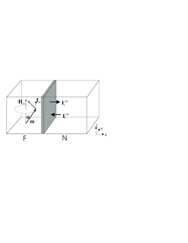
Figure 1: Schematic view of spin
battery operated by ferromagnetic resonance. The dotted line
represents the dc component of pumping current.
The “spin battery” operated by ferromagnetic
resonance has been proposed by Brataas et al. Brataas et al. (2002) in
the limit of weak spin flip scattering in the ferromagnet. It is based on the
spin current pumped into a normal metal by a moving magnetization
() Tserkovnyak et al. (2002a)
(1)
where is the unit vector of magnetization. and are the
real and imaginary parts of the (dimensionless) spin-mixing conductance
Brataas et al. (2000). This spin current creates a spin
accumulation in the normal metal, which induces a backflow of
spins, and, as we will see, charges the ferromagnet. According to
magnetoelectronic circuit theory Brataas et al. (2000) the charge and spin
currents flowing through the interface (into N) in the
presence of non-equilibrium charge and spin accumulations
in N and , in F, read
Brataas et al. (2000)
(2)
where is the total interface conductance of
spin-up and spin-down electrons, is the contact polarization given by
. For typical
metallic interfaces, the imaginary part of the mixing conductance is quite
small Xia et al. (2002), hence discarded in the following discussion . We choose
the transport direction along the -axis that is perpendicular to the
interface at the origin. , the sum of DC external and
uniaxial anisotropy magnetic fields, points in the -direction, which is
also the chosen spin quantization axis in the normal metal. At the
ferromagnetic resonance, the magnetization precesses steadily around the
-axis with azimuthal angle (see Fig. 1) that is
tunable by the intensity of an AC magnetic field. The thickness of the normal
and ferromagnetic metal films are and , respectively.
is determined by the spin-diffusion equation
Johnson and Silsbee (1988)
(3)
where is the spin-flip relaxation time and the
diffusion constant in the normal metal. Assuming that the magnetization
precesses around the -axis with angular velocity , we consider the
limit where the spin-diffusion length in the normal metal is much larger than
the transverse spin-averaging length ,
i.e., , or equivalently . We can then distinguish two regimes. When the thickness of
the normal metal , which is equivalent to the Thouless
energy , the oscillating transverse
component of the induced spin accumulation vanishes inside the normal metal,
and one is left with a time-dependent spin accumulation along -axis
decaying away from the interface on the scale . The backflow
due to the steady state spin accumulation aligned along the -axis cancels
the same component of the pumping current. The former acquires the universal
value when the spin-flip scattering is sufficiently weak
Brataas et al. (2002). The opposite regime of ultrathin or ultraclean normal metal
films in which the spin accumulation
is governed by a Bloch equation and will be discussed elsewhere
Wang and Bauer (2006).
Continuity of the total spin current into the normal metal at the interface
(4)
is the first boundary condition for the diffusion equation, where is the one-spin density of states and
the area of the interface, and the second is its vanishing at the sample
edge . The time-averaged
solution of Eq. (3) reads with
(5)
The component of the spin accumulation parallel to the magnetization is a
constant for the precessional motion considered here. It can penetrate the
ferromagnet, hence building up a spin accumulation in F, which obeys the spin diffusion equation
Johnson and Silsbee (1988)
(6)
where is the spin-flip diffusion length in the ferromagnet.
The boundary conditions are given by the continuity of the longitudinal spin
current at the interface
(7)
and a vanishing spin current at the outer boundary
(8)
where is the conductivity of spin up (down)
electrons in the ferromagnet Tserkovnyak et al. (2002b). In the steady state there
can be no net charge flow. From follows that a charge chemical
potential difference builds up across the contact. At the interface on the F side,
the longitudinal component of the total spin current leaving the ferromagnet
then reads
(9)
The interface resistance is in series with a resistance of the bulk normal metal of
thickness that accounts for the averaging of the transverse spin
current components. This reduces the interface conductances for spin-up (down)
electrons to and the spin-mixing conductance
We also
introduce
(10)
Solving Eq. (6) under the above boundary conditions gives
(11)
where and is a parametrizes the properties of the bulk ferromagnet
Tserkovnyak et al. (2002b). When the spin-flip in F is negligible, i.e.,
, then
and consequently the longitudinal spin current vanishes. In the present limit,
, the time-averaged pumping current Eq.
(4) reads and the spin accumulation in N
at distance near the interface becomes
(12)
where we have introduced the reduction factors for N and F:
(13)
where and .
With weak spin-flip in F, i.e., , and Eq. (12) reduces to
Brataas et al. (2002). Increasing the spin flip in F or the ratio , the factor gets larger and
the spin accumulation signal decreases accordingly. More interesting is the
chemical potential bias that builds
up across the interface, for which we find
(14)
where We now estimate the magnitude of
and for the typical systems PyAl jedema2001 .
In Al the spin diffusion length is , the spin-flip time (at low temperature) and the density of states of Al is . The mixing conductance of the PyAl interface in a diffuse
environment can be estimated as twice the Sharvin conductance of Al
Bauer et al. (2003) to be . The bare contact polarization is taken as
. The spin-flip length in Py is very short, around Bass and Pratt (1999) and is about Fert and Piraux (1999). Assuming a magnetization precession cone of
, the voltage of PyAl interface as a
function of the FMR frequency is plotted in Fig. 2. The
induced spin accumulation in the normal metal and the voltages across the
interface as a function of are plotted in Fig. 3. The
voltage bias across the interface, for given bulk properties of the normal
metal, is seen to saturate at large spin-flip scatterings on the F side
. Spin-flip in the normal metal is detrimental to
both spin accumulation and voltage generation. On the other hand, a
transparency of the contact reduced from the Sharvin value increases the
polarization up to its bare interface value and with it the
voltage signal (up to a maximum value governed by the reduction factor
that wins in the limit of very low transparancy).
The angle dependence of the voltage across the interface is plotted in the
inset of Fig. 2 in the limit of large spin flip in F
. When (but still
) we obtain the maximum value:
(15)
given . At small angle
of the magnetization precession
(16)
In the opposite limit, (but ) the voltage drop becomes
(17)
which in the limit of small angle reduces to . In both limits at
small precession angles, the voltages are proportional to ,
i.e., increases linearly with power intensity of the AC field. Eqs.
(15) and (17) as function of FMR frequency are
depicted in Fig. 2 as solid and dashed lines.
In contrast to Berger Berger (1999), who predicted voltage generation in
spin valves, viz. that dynamics of one ferromagnet causes a voltage
when analyzed by a second ferromagnet through a normal metal spacer, we
consider here a simple bilayer. The single ferromagnetic layer here serves
simultaneously as a source and detector of the spin accumulation in the normal
metal layer. The presence of spin-flip scattering that allows the back-flow of
a parallel spin current is essential, and permalloy is ideal for this purpose.
The voltage bias under FMR conditions can be measured simply by separate
electrical contacts to the F and N layers. It can be detected even on a single
ferromagnetic film with normal metal contacts Azevedo et al. (2005), provided
that the two contacts are not equivalent.
Figure 2: The voltage
drop (in ) as function of FMR frequency (in
) for PyAl interface. The line with circles denotes the
situations when (empty symbols) and
(filled symbols) when the thickness of
ferromagnet is taken as . The solid and dashed
lines refer to the limits as indicated by Eq. (15) and Eq.
(17). These curves indicate that due to averaging of the
transverse spin components inside the normal metal, the voltage is not linear
with FMR frequency. The precession angle of magnetization is taken as
. The inset shows the angle dependence of the voltage at
fixed frequency . At small angle, the voltage drop is
proportional to .Figure 3: Lines with circles are
the spin-pumping induced accumulation (in unit of ) in Al near the interface to permalloy as a function of the Py layer
thickness and two Al layer thicknesses, i.e., (empty symbols) and
(filled symbols). Solid()and dotted() lines are the chemical potential discontinuity across
the interface (in units of ), as a
function of the Py layer thickness . The FMR frequency is 15.5
.
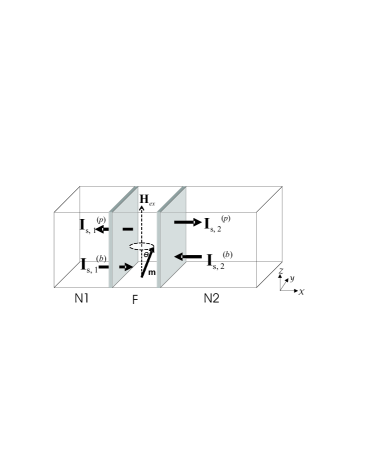
We can also study the FMR generated bias in a controlled way in the NF
N2 trilayers in which the F layer is sandwiched by two normal metal
layers. The magnetization of the ferromagnet again precesses around the
-axis. The thicknesses of , F and in the
transport direction are , and respectively. The spin
diffusion length in normal metal node i is . With weak
spin flip in the sandwiched ferromagnetic layer, ,
the spin accumulation of F at both interfaces are the same. We find that the
values of near the interfaces are mixtures of the interface
values of the spin accumulations in the normal metals. In other words, the two
normal metals talk to each other through F by the backflow and
the generated voltages across the interfaces are different given different contacts.
In the opposite
limit with massive spin flip in F, , the strong spin
flip scattering eventually separates the spin accumulation in the two normal
metal nodes such that the “exchange” between the two normal metals is suppressed. We then recover Eq.
(11).
According to Eq. (14) the voltage drops across the interfaces,
and are different for different
spin-diffusion lengths in the normal metals () or different
conductances (). For example, taking
identical normal metals but different contacts, e.g., a clean and a
dirty one, and will be
different due to different spin-mixing conductances.
Figure 4: The NF N2 system in which the sandwiched F layer
precesses around the -axis under FMR condition. The origin of the -axis
is located at the interface.
In conclusion, we report a unified description for spin pumping in FN
structure and analyze the spin accumulation in the normal metal induced by a
spin-pumping current. We predict generation of a DC voltage over a single
FN junction. The PyAl system should be an ideal candidate to
electrically detect magnetization dynamics in this way. An experimental test
of our predictions is in progress Costache .
Acknowledgements.
We thank Yu. Nazarov and A. Kovalev for discussions. This work is supported by
NanoNed, FOM and the Research Council of Norway through grant no. 162742/V00.
References
(1)
(2)
(3)
(4)
Tserkovnyak et al. (2002a)Y. Tserkovnyak,
A. Brataas, and
G. E. W.
Bauer, Phys. Rev. Lett
88, 117601 (2002a).
Tserkovnyak et al. (2005)Y. Tserkovnyak,
A. Brataas,
G. E. W.
Bauer, and
B. Halperin,
Rev. Mod. Phys. 77,
1375 (2005).
Brataas et al. (2002)A. Brataas,
Y. Tserkovnyak,
G. E. W. Bauer, and
B. I.
Halperin, Phys. Rev. B
66, 060404 (2002).
Watts et al. (2006)S. M. Watts,
J. Grollier,
C. H. van der Wal, and
B. J. van
Wees, Phys. Rev. Lett. 96,
077201 (2006).
Berger (1999)L. Berger,
Phys. Rev. B 59,
11465 (1999).
(10)J. N. Kupferschmidt, S. Adam, and P. W. Brouwer, cond-mat/0607145.
Azevedo et al. (2005)A. Azevedo,
L. H. V.
Leo?=, R. L.
Rodriguez-Suarez, A. B.
Oliveira, and S. M.
Rezende, J. Appl. Phys.
97, 10C715 (2005);
E. Saitoh, M. Ueda, M. Miyajima, and G. Tatara, Appl. Phys. Lett. 88,
182509 (2006).
(12)M.V. Costache, M. Sladkov, C.H. van der Wal, and B.J. van
Wees, unpublished.
Brataas et al. (2000)A. Brataas,
Y. V. Nazarov, and
G. E. W.
Bauer, Phys. Rev. Lett
84, 2481 (2000);
Eur. Phys. J. B 22,
99 (2001).
Xia et al. (2002)K. Xia,
P. J. Kelly,
G. E. W. Bauer,
A. Brataas, and
I. Turek,
Phys. Rev. B 65,
220401 (2002);
A. Brataas,
G. E. W. Bauer, and
P. J. Kelly,
Phys. Rep. 427,
157 (2006).
Johnson and Silsbee (1988)M. Johnson and
R. H. Silsbee,
Phys. Rev. B 37,
5312 (1988).
Wang and Bauer (2006)X. Wang,
G. E. W. Bauer,
A. Brataas, and
Y. Tserkovnyak
unpublished (2006).
Tserkovnyak et al. (2002b)Y. Tserkovnyak,
A. Brataas, and
G. E. W. Bauer,
Phys. Rev. B 67,
140404 (2003b).
(18)F. J.
Jedema, H. B.
Heersche, A. T.
Filip, J. J. A.
Baselmans,and B. J.
van Wees, Nature
416, 713 (2002);
M. Zaffalon and
B. J. van Wees,
Phys. Rev. Lett. 91,
186601 (2003).
Bass and Pratt (1999)J. Bass and
W. P.
Pratt, J. Magn. Magn. Mater.
200, 274 (1999).
Bauer et al. (2003)G. E. W. Bauer,
Y. Tserkovnyak,
D. Huertas-Hernando, and
A. Brataas,
Phys. Rev. B 67,
094421 (2003).
Fert and Piraux (1999)A. Fert and
L. Piraux,
J. Magn. Magn.
Mater. 200, 338 (1999).