,
Screening Model of Magnetotransport Hysteresis Observed in Bilayer Quantum Hall Systems
Abstract
We report on theoretical and experimental investigations of a novel hysteresis effect that has been observed on the magnetoresistance of quantum-Hall bilayer systems. Extending to these system a recent approach, based on the Thomas-Fermi-Poisson nonlinear screening theory and a local conductivity model, we are able to explain the hysteresis as being due to screening effects such as the formation of “incompressible strips”, which hinder the electron density in a layer within the quantum Hall regime to reach its equilibrium distribution.
I Introduction
Recent scanning force microscope experiments Ahlswede01:562 ; Ahlswede02:165 and subsequent theoretical work Guven03:115327 ; siddiki2004 have shown that screening effects, notably the occurrence of “incompressible strips” Chklovskii92:4026 ; Siddiki03:125315 , are very important for the understanding of the Hall-field and current distribution as well as the high precision of the low-temperature integer quantized Hall (QH) effect in narrow Hall samples. Since Coulomb interactions should become important within and between the layers of an electron bilayer system showing the drag effect Gramila91:1216 ; Zheng93:8203 ; Bonsager97:10314 at very low temperatures, we extended the theory of Ref. siddiki2004 to the bilayer case and calculated the Hall and longitudinal resistances for density-matched and mismatched systems. Magnetoresistance (MR) measurements on separately contacted bilayers, which were performed to check the results, showed pronounced hysteresis effects, similar to results reported previously for hole tutuc and electron pan double layers. In contrast to this previous work, our approach makes the origin of the hysteresis rather evident: the peculiar nonlinear screening properties leading to the occurrence of “incompressible strips” in the QH regimes of the individual layers.
II The Experiments
We measured the MRs of both layers as functions of the applied perpendicular magnetic field and the sweep direction for matched and mismatched densities at a fixed base temperature (mK) within the linear response regime (nA).
We also performed “equilibrium” measurements, where the system was heated up to K and cooled down again at each magnetic sweep step, in the magnetic field interval where hysteresis is observed. The samples are nm wide GaAs/AlGaAs double quantum well structures grown by MBE and capped by top and bottom gates that control the electron densities of the layers. Two 2DES are confined by doping remote Si donors and are separated by a spacer of thickness nm. For such a separation the bilayer system is electronically decoupled, i.e. electron tunneling between the layers (M) is not possible and the system can be described by two different electrochemical potentials. Separate Ohmic contacts to the two layers are realized by a selective depletion technique Eisenstein90:2324 . The samples were processed into m wide and m long Hall bars, with grown densities in the range m-2, the mobility is m2/Vs per layer.
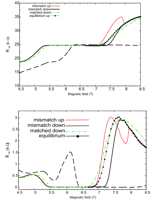
Figure 1 shows Hall and longitudinal resistances of the top layer versus magnetic field strength, measured under different conditions. As a reference, the resistances of the bottom layer (long-dashed lines) are also shown for one sweep direction in the mismatched case. In the “equilibrium measurements” (solid lines with symbols) explained above and also in the case of matched densities the resistances are insensitive to the sweep direction. Note that the QH plateau for matched densities is narrower than that of the mismatched system in the “equilibrium measurement”. For the density mismatched (and non-equilibrium) case, the data were taken at a sweep rate T/min and the base temperature is always kept at mK. Apparently the resistances of the top layer follow different traces for the up- (red dotted lines) and the down- (black solid lines) sweep.
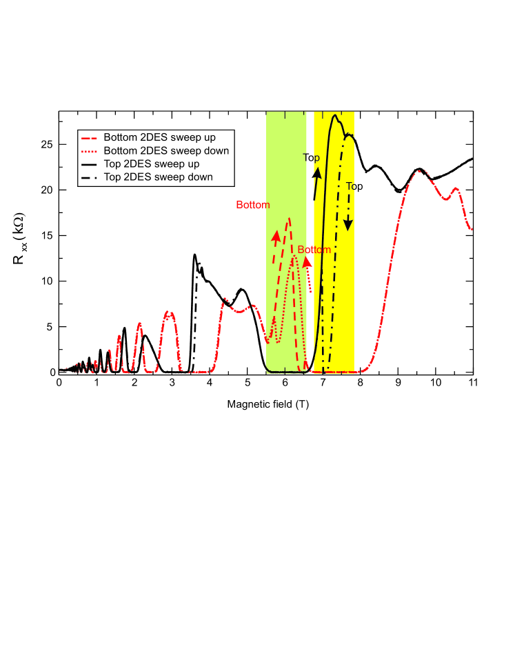
Figure 2 shows that, for density-mismatched bilayers, hysteresis occurs in both layers under comparable conditions. The hysteresis shown in Fig. 1 occurs in the top layer near the high- edge of the QH plateau (plateau region TT). It occurs in a -interval well within the QH plateau (TT) of the bottom layer. Similarly, the MR of the bottom layer shows hysteresis at the low- edge of its QH plateau, in a -interval well within the QH plateau of the top layer. No hysteresis is observed in magnetic field intervals in which the other layer is in the normal state, with finite longitudinal resistance. A less pronounced repetition of these features is observed in the plateau regimes.
III The Model
We model the electron bilayer system as a series of parallel charged planes, perpendicular to the -direction, translation invariant in the -direction, and confined to . The bottom and top 2DESs with number densities and lie in the planes and , respectively. Ionized donor layers with number densities and are assumed at and , and a top gate at , allowing for a density mismatch even with , is simulated by ionized donors with number density at . Solving Poisson’s equation with the boundary condition , we obtain from the charge densities in the plane as contribution to the potential energy of an electron at position :
| (1) |
with the kernel Siddiki03:125315 , where , , and . We write the total potential energy of an electron as
| (2) |
where is the sum of the potentials created by bottom electron and donor layer, while is the sum of the potentials due to the top electron, donor, and gate layers. The electron number densities in the layers are, within the Thomas-Fermi approximation (TFA),
| (3) |
with or and the (collision-broadened) Landau density of states. This completes the self-consistency scheme Guven03:115327 ; siddiki2004 . In the practical calculations we first decoupled the layers, replacing by , and solved the single electron-layer problem for bottom and top system separately. There it is convenient to fix the edges of the electron density profile in the limit of zero magnetic field and temperature Guven03:115327 ; siddiki2004 , which fixes the average density (and ). With the converged results at finite and , we treat the inter-layer coupling iteratively.
To describe the density-mismatched case, we add more electrons to the top layer by setting to a positive value and keeping the depletion length fixed. We scale energies by the average Fermi energy , e.g. .
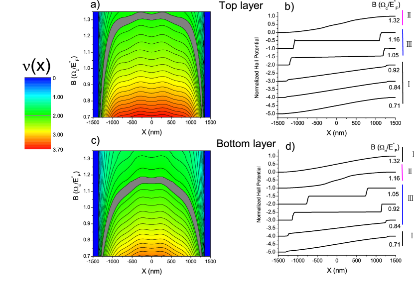
Next we implement in each electron layer a quasi-local model to impose a current, following the lines of Ref. siddiki2004 . It is based on a local version of Ohm’s law, between current density to driving electric field . The position-dependent conductivity tensor is taken from a bulk calculation Ando82:437 , with the electron density replaced by the local one, and a spatial smoothening over a length of the order of the Fermi wave length is performed, in order to avoid unphysical artifacts of a strictly local transport model and of the TFA siddiki2004 . Typical results with a slightly modulated donor distribution , introduced to simulate the long-range-part of the impurity potentials siddiki2004 , are shown in Fig. 3.
IV Simulation of non-equilibrium
The quasi-equilibrium model just introduced is, of course, not able to describe hysteresis effects. It yields, however, qualitatively correct results for the matched density case (), where the MRs for both layers are identical, and for the mismatched systems it yields results in qualitative agreement with those found in the “equilibrium measurements”. Moreover, the results shown in Fig. 3 give some hints towards the possible origin of the hysteresis effects. We see that, in the plateau regime of the QH effect, i.e., in the magnetic field interval in which incompressible strips (ISs) exist siddiki2004 , the position of the incompressible strips [local filling factor ] and the potential distribution change drastically. To realize these changes, electrons must be transported, e.g. by thermal activation, across the ISs. In real samples (of finite length) this is extremely difficult, since states at the Fermi level exist on both sides of an IS but not within the IS, and since the region between ISs is not connected to the contacts. Therefore, after a slight change of the magnetic field, it may take an extremely long time until the electron density relaxes to its new equilibrium distribution jhuels2004 ; Zhu2000 .
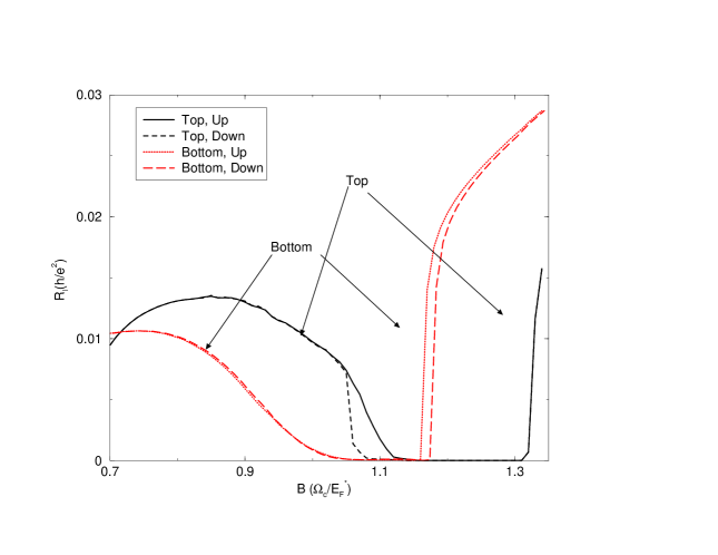
To simulate this hindered approach to equilibrium, we calculate the MRs of the current-carrying layer in a -interval in which the other layer exhibits a QH plateau, using different frozen-in density and potential distributions for up- and down-sweeps of the magnetic field . For the down-sweep, we freeze in the density profile of the other layer at the high- edge of its QH plateau and for the up-sweep we freeze it in at the low- edge, and use these fixed potentials to describe the other layer when calculating the equilibrium and transport properties of the current-carrying layer. Thus, for the case shown in Fig. 3, we calculate the MRs of the bottom layer in the QH plateau regime of the top layer by fixing the potential due to the top layer at for the down-sweep and at for the up-sweep. To calculate the MRs of the top layer in the plateau regime of the bottom layer, we fix the potential profile of the bottom layer at for the down-sweep and at for the up-sweep. Since the MRs slightly outside the QH plateau regimes depend on the electron and current density profiles siddiki2004 , we will obtain slightly different results for the different sweep directions. Figure 4 shows longitudinal magnetoresistances calculated along such lines.
V Summary
We report on measurements and calculations of the magnetoresistances in separately contacted e-e bilayer systems. The calculation, based on a self-consistent Thomas-Fermi-Poisson theory of the equilibrium state and a quasi-local transport theory siddiki2004 , yields reasonable agreement with the measurements for density-matched layers and for mismatched layers, if the measurement allows for thermal relaxation at each value of the magnetic field . -sweeps at constantly low temperature show hysteresis between up and down sweep in the current-carrying layer, provided the other layer exhibits the quantized Hall effect. A model, based on the existence of incompressible regions in the quantum Hall states siddiki2004 and the extremely long relaxation times in compressible regions surrounded by incompressible ones jhuels2004 , is worked out and can explain the observed hysteresis effects.
References
- (1) E. Ahlswede et al., Physica B 298, 562 (2001).
- (2) E. Ahlswede, J. Weis, K. von Klitzing, and K. Eberl, Physica E 12, 165 (2002).
- (3) K. Güven and R. R. Gerhardts, Phys. Rev. B 67, 115327 (2003).
- (4) A. Siddiki and R. R. Gerhardts, Phys. Rev. B 70, 195335 (2004).
- (5) D. B. Chklovskii, B. I. Shklovskii, and L. I. Glazman, Phys. Rev. B 46, 4026 (1992).
- (6) A. Siddiki and R. R. Gerhardts, Phys. Rev. B 68, 125315 (2003).
- (7) T. J. Gramila et al., Phys. Rev. Lett. 66, 1216 (1991).
- (8) L. Zheng and A. H. MacDonalds, Phys. Rev. B 48, 8203 (1993).
- (9) M. C. Bonsager, K. Flensberg, B. Y. K. Hu, and A. P. Jauho, Phys. Rev. B 56, 10314 (1997).
- (10) E. Tutuc et al., Phys. Rev. B 68, 201308 (2003).
- (11) W. Pan, J. Reno, and J. Simmons, cond-mat/0407577 (2004).
- (12) J. P. Eisenstein, L. N. Pfeiffer, and K. W. West, Appl. Phys. Lett. 57, 2324 (1990).
- (13) T. Ando, A. B. Fowler, and F. Stern, Rev. Mod. Phys. 54, 437 (1982).
- (14) J. Huels et al., Phys. Rev. B 69, 085319 (2004).
- (15) J. Zhu et al., Phys. Rev. B 60, 5536 (1999).