Structure peculiarities of cementite and their influence on the magnetic characteristics
Abstract
The iron carbide is studied by the first-principle density functional theory. It is shown that the crystal structure with the carbon disposition in a prismatic environment has the lowest total energy and the highest energy of magnetic anisotropy as compared to the structure with carbon in an octahedron environment. This fact explains the behavior of the coercive force upon annealing of the plastically deformed samples. The appearance of carbon atoms in the octahedron environment can be revealed by Mossbauer experiment.
pacs:
75.50.Bb, 75.60.Cn, 71.15.ApI Introduction
The study of the properties of cementite, that is of iron carbide , has been conducted for a long time. Originally, cementite was investigated as a component of steels that essentially affects their mechanical properties. Some attention was paid to the magnetic properties in connection with nondestructive methods of the steel control.
A recent splash of interest in the properties may be explained, first, by new possibilities of obtaining metastable compounds with mechanical alloying, implantation and so forth (see, for example, Refs. Els1 ; Reed ; Koniger ; Umemotoa ). Besides, the monophase by itself has attracted considerable interest due to the peculiarities in the bulk modulus behavior Duman1 and the instability of the magnetic state under pressure Lin ; Duman2 . Finally, an additional impact has been given by the studies dealing with the chemical composition of the Earth’s core Wood .
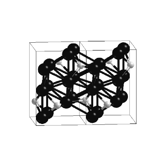
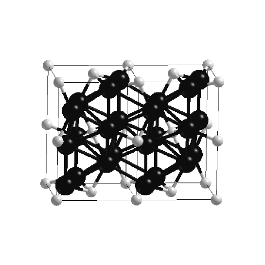
The cementite structure is believed to be known well enough Fasiska as for the arrangement of iron atoms that is well detected by X-ray diffraction. The carbon disposition in the lattice is still not clear. According to Ref. Schastl the carbon atoms can occupy 4 positions between the iron sites. Two of them (prismatic and octahedron, Fig. 1 and 2) were repeatedly specified as possible places of the carbon atoms. The two other named by authors of Ref. Schastl distorted prismatic and octahedron positions were not discussed earlier. Carbon in the two last positions is very close to iron atoms and these configurations look improbable. The contemporary experiments cannot still give unequivocal verification of the carbon positions. The present-day experimantal data on cementite testify only that the carbon positions actually depend on the mechanical and thermal treatment. The relevant structural changes manifest themselves in both the mechanical and magnetic properties. Fig. 3 taken from Ref. Els2 shows the coercive force as a function of the annealing temperature. Its uncommon behavior may be attributed only to the redistribution of the carbon atoms in the system: without such a redistribution, annealing should increase the average grain size (Fig. 3), reduce the imperfections of the sample, and decrease thus the coercive force. One can find other experimental evidence for the changes in the carbon atoms positions, for example, the change in the number of atoms in the nearest environment obtained in EELFS Maratk , changes in the Mossbauer spectra Els3 and so forth.
This paper presents the first-principle calculations conducted in order to determine the position of carbon and its effect on the physical properties. Earlier theoretical investigations of cementite have been carried out in numerous papers (see, for example, Lin ; Medvedeva and their references), but only in Ref. Medvedeva a comparison of some characteristics of the two structures with prismatic and octahedron positions of carbon was done, the relaxation of the crystal lattice being not taken into account.
Models and methods of calculation
The crystal structure of is an orthorhombic lattice with the lattice parameters a=0.4523 nm, b=0.5089 nm, c=0.6743 nm Fasiska . The unit cell contains two nonequivalent iron (4 atoms of Fe 1 type and 8 atoms of Fe 2 type) and one carbon (4 atoms) positions. The closest to iron atoms are carbon atoms, in the second sphere of Fe 1 atom there are 5 iron atoms at slightly different distances, and in that of Fe2 atom there are 8 iron atoms.

The calculations presented in this paper have been conducted with a full-potential linearised augmented plane wave (FLAPW) method in the WIEN2k package WIEN2k . In the FLAPW method the wave functions, charge density and potential are expanded in spherical harmonics within non-overlapping atomic spheres of radius and in plane waves in the remaining space of the unit cell (interstitial region).The basis set is split into the core and valence parts. The core states are treated with the spherical part of the potential and are assumed to have a spherically symmetric charge density totally confined inside the muffin-tin spheres; they are treated in a fully relativistic way. The expansion of the valence wave functions inside the atomic spheres was confined to and they were treated within a potential expanded into spherical harmonics up to . We used an APW+lo-basis Madsen . The wave functions in the interstitial region were expanded in plane waves with a cutoff determined by the relation . The charge density was Fourier expanded up to . First atomic relaxation have been conducted in the scalar-relativistic approximation for the valence electron so that the atoms are in the positions of minimum total energy, where the calculated forces acting on the nuclei equal zero. A mesh of 60 special k-points was taken in the irreducible wedge of the Brillouin zone. Using the unit cell obtained after relaxation, we have conducted calculations of the magnetic characteristics including the spin-orbit coupling through the second variational method WIEN2k (the number of k-points here was increased up to 432).
Results and discussion
We have calculated periodical lattices with different positions of the carbon atoms in the unit cell (Fig. 1 and 2), the lattice parameters being taken equal to the experimental values. In the unit cell the atoms are shifted to the positions of minimum energy, that is, the relaxation of the lattice is made.
Table 1 shows that most essential displacements (7 % for one distance) occur in the lattice with octahedron environment of the carbon atoms; the distances between the iron atoms in the lattice with prismatic position of carbon change by less than 2 %.
| nonrelax | prismatic | octahedron | |
|---|---|---|---|
| Fe2-Fe2 | 0.2495 | 0.2459 | 0.2314 |
| Fe2-Fe2 | 0.2495 | 0.2521 | 0.2460 |
| Fe1-Fe2 | 0.2505 | 0.2515 | 0.2521 |
| Fe2-Fe2 | 0.2543 | 0.2554 | 0.2622 |
| Fe1-Fe2 | 0.2572 | 0.2597 | 0.2596 |
| Fe1-Fe1 | 0.2653 | 0.2663 | 0.2629 |
| Fe2-Fe2 | 0.2653 | 0.2649 | 0.2694 |
| Fe1-Fe2 | 0.2673 | 0.2649 | 0.2640 |
| Fe1-Fe2 | 0.2673 | 0.2671 | 0.2686 |
| Fe1-Fe2 | 0.2700 | 0.2691 | 0.2715 |
In spite of the fact that the displacements mightily decrease the energy of the cell with octahedron position of carbon, the energy of the cell with prismatic position turns out to be lower, (Table 2).
| direction | prismatic | octahedron |
|---|---|---|
| 001 | -30852.09422 | -30851.97410 |
| 010 | -30852.09415 | -30851.97411 |
| .00007 | -.00001 |
This confirms that the lattice with prismatic carbon position and with account of the atomic relaxation has a minimum energy, so, it is the ground state. The difference in energy between the two configurations of the carbon positions testifies that on the one hand the deformation energy under mechanical treatment is sufficient to shift the carbon from the prismatic positions to the octahedron ones, on the other hand the probability of these shifts through thermodynamic fluctuations is small at .
The energy with the spin-orbit coupling included depends on the direction on magnetisation and is given in Table 2.
The magnetic anisotropy energy attracts most attention. Note that for transition metals it is generally difficult to calculate because of its small value being a result of the difference of two large quantities and close to the calculational inaccuracy. In the case under study, in the system with prismatic environment of carbon is much higher than in the system with octahedron carbon position and is calculated more reliably. The calculations show that magnetizing in the [001] direction is more preferable than in the [010] one. The magnetic anisotropy energy - the difference in total energy between the states with magnetization along these two axes per volume - equals:
The easy-magnetization axis and the magnetic anisotropy energy correspond to those obtained in the experiment () made for a monocrystal at a temperature of 20.4 K Blum . Some distinctions may be referred to the calculational inaccuracy or to a possible intermixture of carbon in the octahedron environment in experiment.
For the system with carbon in octahedron environment and is seemingly close to the magnetic anisotropy energy of pure iron . Using a simple model of interacting magnetic moments at the iron sites along the easy axis, one can find the domain wall width (see, for example, Landau ) . Here is the closest distance between the iron atoms, is the exchange energy per volume. Let us estimate from the temperature of the ferromagnet-paramagnet phase transition ( Schastl ): , where is the Boltzmann constant, is the number of iron atoms in the unit cell, is the number of nearest neighbors. So, we obtain . Such a domain wall should be effectively pinned to the defects larger than 10 nm. In Ref. Els2 the samples studied were in the nanocrystalline state with average grain size of nanocrystals ranging from 10 to 60 nm (Fig. 3). It is natural to assume that they are places of the pinning of the domain walls. In the system with octahedron environment of carbon, the domain-wall width is times larger (), and the nanocrystals lesser than 30 nm are of no significance in the formation of the coercive force. During annealing of the deformed cementite, the carbon atoms move from the octahedron positions to the prismatic ones, the total energy decreasing and the coercive force increasing (Fig. 3).
The decrease of the coercive force in the samples after annealing at temperature higher than 700 K is due to a common mechanism: the degree of homogeneity of the crystal state becomes higher with annealing temperature (Fig. 3).
Note that in spite of the large difference in between the lattices with prismatic and octahedron carbon positions the magnitudes of spin or orbital magnetic moments are not very different in these two lattices (see Table 3).
| prismatic | octahedron | |||
| Fe1 | Fe2 | Fe1 | Fe2 | |
| 2.01 | 1.94 | 1.88 | 1.69 | |
| 0.05 | 0.04 | 0.05 | 0.03 | |
| 3.12 | 1.34 | 2.94 | -2.37 | |
| 0.12 | 0.64 | 0.88 | 0.22 | |
Taking into account the fact that the samples always contain some amount of other phases of iron and carbon, the magnetisation measurements do not give a possibility to distinguish the carbon positions. The difference in for systems with equal spin moments and equal orbital moments results from a difference in solely the electron-density distribution. Table 3 shows that the electric field gradients at iron sites in the second inequivalent position are of opposite sign in the systems with prismatic and octahedron environment of carbon. This leads to a quadrupole interaction of different sign, and there should exist a difference in the Mossbauer spectra. The large quadrupole splitting , (, see Ref. Kienle ) and the large share of these atoms in the cell allow one to believe that a difference in the shape of the Mossbauer spectrum may be experimentally observed for the carbon atoms in an octahedron or a prismatic position. Difficulties in interpreting such Mossbauer experiments arise from the simultaneity of the electric and magnetic interactions. The combined hyperfine interaction, the angle between the hyperfine magnetic field and the electric field gradient, and the spatial averaging may essentially complicate the Mossbauer spectrum shape.
Conclusions
With the help of the first-principle calculations we show that the magnetic anisotropy energy of cementite is much higher when the carbon atoms are in the prismatic pores in contrast with the structure when the carbon atoms occupy the octahedron pores. The former structure has a lowest total energy. These calculations explain the experimental behavior of coercive force as a function of the annealing temperature for the plastically deformed samples. The experimental data and the results of calculations confirm a possibility of different carbon disposition between the iron sites in cementite and the movement of carbon atoms during the mechanical or thermal treatment. Such structural changes can be directly detected in the Mossbauer experiment by a change in quadrupole splitting.
Acknowledgments
The authors are grateful to Prof. E. P. Yelsukov and Prof. A. I. Ul’yanov for helpful discussions and for experimental data. This work was partially supported by INTAS (grant 03-51-4778), and RFBR (grant 06-02-16179).
References
- (1) E. P. Elsukov, G. A. Dorofeev, V. M. Fomin, G. N. Konygin, A. V. Zagainov, and A. N. Maratkanova, Phys. Met. Metallogr. 94 (2002) 356
- (2) R. C. Reed and J. H. Root, Scr. Mater., 38 (1998), 95
- (3) A. Koniger, C. Hammerl, M. Zeitler, and B. Rauschenbach, Phys.Rev.B 55 (1997) 8143
- (4) M. Umemotoa, Z. G. Liu, K. Masuyamab, and K. Tsuchiyaa, Scr.Mater. 45 (2001) 391-397
- (5) E. Duman, M. Acet, T. Hulser, E. F. Wassermann, B. Rellinghaus, J. P. Itil, and P. Munsch, J. Appl. Phys. 96 (2004) 5668
- (6) J.-F. Lin, V. V. Struzhkin, H. Mao, R. J. Hemley, P. Chow, M. Y. Hu, and J. Li, Phys. Rev. B 70 (2004) 212405
- (7) E. Duman, M. Acet, E. F. Wassermann, J. P. Itie, F. Baudelet, O. Mathon, and S. Pascarelli, Phys.Rev.Lett. 94 (2005) 075502
- (8) B. J. Wood, Earth Planet.Sci.Lett. 117 (1993) 593
- (9) E. J. Fasiska and G. A. Jeffrey, Acta Cryst. 19 (1965) 463
- (10) V. M. Schastlivtsev, I. L. Yakovleva, D. A. Mirzaev, and K. Yu. Okishev, Phys. Met. Metallogr. 96 (2003) 313
- (11) E. P. Yelsukov, A. I. Ul’yanov, A. V. Zagainov, and N. B. Arsent’yeva, JMMM 258-259 (2003) 513
- (12) A. N. Maratkanova, Y. V. Ruts, D. V. Surnin, A. N. Deev, V. M. Schastlivtsev, I. L. Yakovleva, T. I. Tabatchikova, S. A. Gusev, and N. N. Salashchenko, Phys. Met. Metallogr. 89 (2000) 6, 604
- (13) E. P. Elsukov, V. M. Fomin, D. A. Vytovtov, G. A. Dorofeev, A. V. Zagainov, N. B. Arsent’eva, and S. F. Lomaeva Phys. Met. Metallogr. 100 (2005) 3, 251
- (14) I. N. Medvedeva, L. E. Kar’kina, and A. L. Ivanovskii, Phys. Met. Metallogr. 96 (2003) 452
- (15) P. Blaha, K. Schwarz, G. K. H. Madsen, D. Kvasnicka and J. Luitz, WIEN2k, An Augmented Plane Wave + Local Orbitals Program for Calculating Crystal Properties (Karlheinz Schwarz, Techn. Universitat Wien, Austria), 2001. ISBN 3-9501031-1-2.
- (16) G. K. H. Madsen, P. Blaha, K. Schwarz, E. Sjöstedt, and L. Nordström, Phys. Rev. B 64 (2001) 195134
- (17) P. Blum and R. Pauthenet, Compt.Rend. 237 (1953) 1501
- (18) L. D. Landau and E. M. Lifshitz, Sow. Phys. 8 (1935) 157
- (19) P. Kienle, Phys.Verhandl. 3 (1963) 33