Coexistence and competation of local- and long-range polar orders in a ferroelectric relaxor
Abstract
We have performed a series of neutron diffuse scattering measurements on a single crystal of the solid solution Pb(Zn1/3Nb2/3)O3 (PZN) doped with 8% PbTiO3 (PT), a relaxor compound with a Curie temperature T K, in an effort to study the change in local polar orders from the polar nanoregions (PNR) when the material enters the ferroelectric phase. The diffuse scattering intensity increases monotonically upon cooling in zero field, while the rate of increase varies dramatically around different Bragg peaks. These results can be explained by assuming that corresponding changes occur in the ratio of the optic and acoustic components of the atomic displacements within the PNR. Cooling in the presence of a modest electric field oriented along the [111] direction alters the shape of diffuse scattering in reciprocal space, but does not eliminate the scattering as would be expected in the case of a classic ferroelectric material. This suggests that a field-induced redistribution of the PNR has taken place.
pacs:
77.80.-e, 77.84.Dy, 61.12.ExI Introduction
Lead perovskite relaxor systems such as Pb(Zn1/3Nb2/3)O3 (PZN) and Pb(Mg1/3Nb2/3)O3 (PMN) have been the focus of intense scientific scrutiny in recent years because they display exceptionally strong dielectric and piezoelectric properties Park and Shrout (1997). These systems are marked by a strong, frequency-dependent dielectric permittivity that exhibits relaxation processes on many different time scales. This relaxational character has been attributed to the presence of small-scale regions of the lattice that possess randomly oriented, local polarizations, and which first appear at a temperature , often referred to as the Burns temperature Burns and Dacol (1983). In PMN, for example, (650 K) lies a few hundred degrees above , the temperature at which the dielectric permittivity is largest. Neutron scattering studies by Naberezhnov et al. have demonstrated the onset of strong diffuse scattering in PMN near , thus indicating a strong link with the PNR. These polar nanoregions, or PNR, are believed to be several nanometers in size, grow with cooling, and are widely viewed to play important roles in determining relaxor properties Cross (1987). For this reason we have undertaken a comprehensive study of the PNR properties using neutron diffuse scattering techniques.
Diffuse scattering is very sensitive to local inhomogeneities and short-range order in solid materials. It is thus an extremely powerful tool with which to study the structure of the PNR. Neutron and x-ray elastic diffuse scattering measurements on relaxor systems can provide important information about the size, shape, and polarization of the PNR. The data collected by Vakhrushev et al. Vakhrushev et al. (1995) on the diffuse scattering intensity measured along directions transverse to the wavevector near many Bragg peaks in PMN provided the first quantitative study of the relative magnitudes of the atomic displacements (polarizations) within the PNR. In a subsequent study by Hirota et al. Hirota et al. (2002) the authors proposed the concept of the uniform phase shift, whereby the atomic displacements responsible for the PNR could be decomposed into two components: an acoustic term that corresponds to a uniform shift of the entire PNR relative to the surrounding lattice, and an optic term that results from the condensation of a transverse optic (TO) phonon. Two other important features of the PNR are the directions of the polarizations and the shape of the PNR. These issues have also been extensively studied by diffuse scattering and other techniques Xu et al. (2004a); Hiraka et al. (2004); Hlinka et al. (2003); Dkhil et al. (2001); You and Zhang (1997); Takesue et al. (2001); Jeong et al. (2005). Recently, Xu et al. Xu et al. (2004b) studied the three-dimensional diffuse scattering distribution in single crystals of PZN and its derivatives. These authors found that the diffuse scattering consists of six rods. A model was proposed where -type polarizations are correlated in {110} planes, thus implying a “pancake” shape for the PNR with polarizations that lie in-plane.
Of course, with diffuse scattering measurements, it is not always easy to distinguish subtle differences in the local structure. In other words, are these PNR really nano-meter sized polar domains with well-defined boundaries; or just local polar fields with short-range correlations? The former correspond to a square-function type polar correlation, while the latter can be described with a gradually decaying, e.g., exponentially decaying correlation function with a certain length scale. In both cases, local polar moments due to optic type atomic displacements exist in the system, as proposed by Burns and Dacol in their original PNR picture; and both can result in very similar diffuse scattering line shapes in thee reciprocal space. In this paper, we do not attempt to make such a distinction. For simplicity, the term “PNR” is used throughout the paper. And when the “size” or “shape” of the PNR is concerned, they can be viewed alternatively as length scales describing the local polar field (instead of the size of a well defined nano-region).
Considered by many researchers to be precursors to the ferroelectric phase transition, the PNR were expected to co-align or form much larger ferroelectric domains when the system is driven into a ferroelectric phase, either by cooling or by application of an external dc electric field. However diffuse scattering measurements have provided little such indication. Upon cooling in zero field, the diffuse scattering intensities increase monotonically in both PZN Stock et al. (2004) and PMN Xu et al. (2004a) while the shape of the scattering remains the same, suggesting that the PNR persist at low temperatures. The effects of an external dc field on the diffuse scattering are more complicated; some studies Vakhrushev et al. (1998); Gehring et al. (2004) show a partial suppression of the diffuse scattering measured along the [110] and [001] directions, while more recent work Xu et al. (2005, 2006) indicate a redistribution of the PNR takes place when subjected to an external field oriented along the [111] direction. These studies indicate that in relaxor systems, that local- and long-range polar orders coexist and compete with each other.
The unit cells of pure PZN Xu et al. (2003, 2004c) and PMN Bonneau et al. (1989); de Mathan et al. (1991) remain cubic when cooled in zero field; thus neither compound exhibits long-range ferroelectric order at low temperature. However, doping with PbTiO3 (PT) to form the solid solutions PZN-PT and PMN-PT gradually suppresses the relaxor character and establishes a ferroelectric phase Ye et al. (2003). By increasing the PT content each system can be driven across a morphotropic phase boundary (MPB) Kuwata et al. (1981); Noheda et al. (2002); La-Orauttapong et al. (2002) where a more conventional ferroelectric phase Feng et al. (2004); Ohwa et al. (2001) is achieved. In this paper, we report neutron diffuse scattering measurements on PZN-8%PT, which does undergo a ferroelectric phase transition upon zero-field cooling. The low temperature phase has a rhombohedral structure with type polarizations. Being on the relaxor side of the phase diagram, PZN-8%PT also exhibits relaxor properties and strong diffuse scattering Gehring et al. (2004); Xu et al. (2004b, 2005). The 8%PT content is also the composition at which the piezoelectric response is maximum Kuwata et al. (1981), thus making the PZN-8%PT compound a particularly interesting choice of system in which to study the PNR in a ferroelectric phase.
We have studied how the diffuse scattering changes when PZN-8%PT is cooled into the ferroelectric phase under (i) zero field and (ii) an external field oriented along the [111] direction. The zero-field-cooling (ZFC) data show that the diffuse scattering has the same shape in the high temperature paraelectric and low temperature ferroelectric phases. The observed increase in total diffuse scattering intensity on cooling indicates a corresponding growth in the total PNR volume, or an increase in the PNR polarization, or both. However, there is a change in the ratio of the acoustic and optic components of the atomic displacements in the PNR. Specifically, the uniform shift of the PNR grows with decreasing temperature, which suggests that a “pinning” effect takes place in the low temperature phase. After field cooling (FC), a clear redistribution of the diffuse scattering intensity is observed around all Bragg peaks, while the total (integrated) diffuse scattering intensity appears to be conserved, i. e. is at least equal to that in the ZFC case.
II Experiment
The PZN-8%PT single crystal used in this study is rectangular in shape, having dimensions of mm3 with 111, 11, and 01 surfaces, and was provided by TRS Ceramics. Cr/Au electrodes were sputtered onto the top and bottom 111 crystal surfaces. This is the same crystal that was used in Ref. Xu et al., 2005, which reported structural transitions from a cubic to tetragonal phase at K, and then to a rhombohedral phase at K in zero field. Upon cooling in a moderate electric field of kV/cm oriented along the [111] direction, the value of K, while K does not change.
The neutron diffuse scattering measurements were performed with the BT9 triple-axis spectrometer located at the NIST Center for Neutron Research. The measurements were made using a fixed incident neutron energy of 14.7 meV, obtained from the (002) Bragg reflection of a highly-oriented pyrolytic graphic (HOPG) monochromator, and horizontal beam collimations of 40’-40’-S-40’-80’ (”S” = sample). The (002) reflection of an HOPG analyzer was used to select the energy of the scattered neutron beam. Two PG filters were placed before and after the sample to reduce the scattering from higher order reflections. Data were taken in the (HKK) scattering plane, defined by the two primary vectors [100] and [011], with the [111] electric field direction lying in the plane and the 01 crystal surface pointing vertically. All measurements were performed while cooling, starting from 550 K so that all residual (poling) effects are removed.
III Results and Discussion
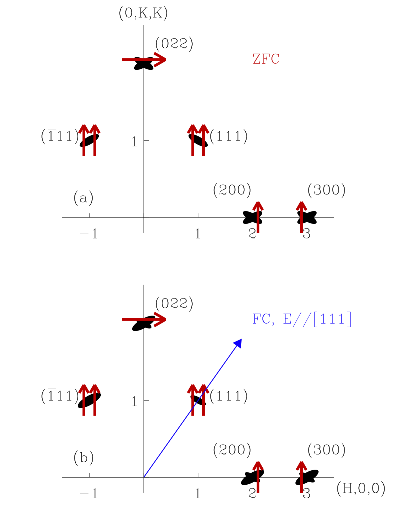
Previous measurements Xu et al. (2005) have confirmed that the diffuse scattering intensities in PZN-8%PT form “butterfly” shaped patterns in zero field in the (HKK) scattering plane; this is shown schematically in Fig. 1 (a). These butterfly patterns are in fact the result of the tails of out-of-plane rods of diffuse scattering intensity, which are visible because of the non-zero instrumental out-of-plane wavevector () resolution. The “”-shaped wing of the butterfly pattern measures the tails of diffuse rods oriented along the [110] and [101] directions, which arise from PNR having polarizations pointing along the [10] and [10] directions; the “”-shaped wing measures the tails of diffuse rods oriented along the [10] and [10] directions, which arise from PNR having polarizations pointing along the [110] and [101] directions. An efficient way to monitor changes in the diffuse scattering is to perform linear -scans in reciprocal space that are offset from the Bragg peak, as shown by the (red) arrows in Fig. 1. These linear scans have the advantage of being able to monitor the intensity changes in both the “” and “” wings of the butterfly pattern, which would not be possible with a (transverse) linear scan that cut across the Bragg peak itself.
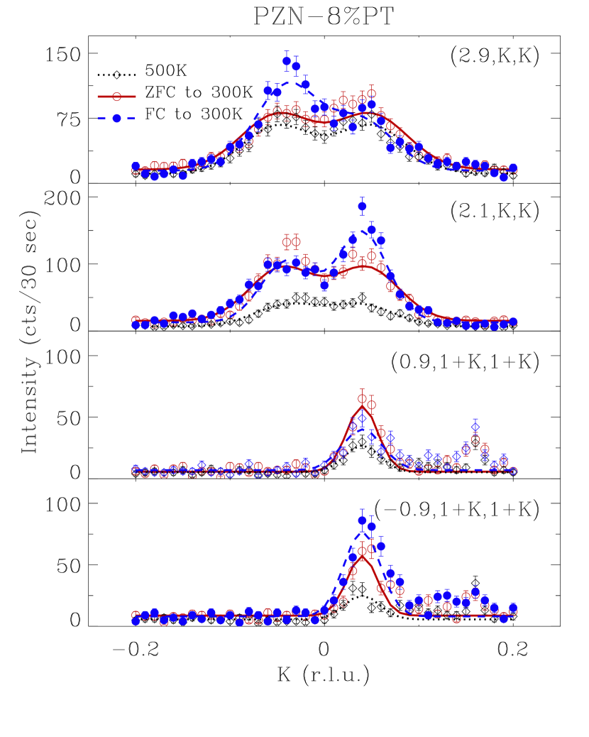
Some of these linear scans are plotted in Fig. 2. We note that the linear scans near (300) (measured along (2.9,K,K)) and (200) (measured along (2.1,K,K)) produce a double-peak profile because the diffuse scattering intensity peaks at each wing of the butterfly pattern. By contrast the scans near (111) (measured along (0.9,K,K)) and (11) (measured along (-0.9,K,K)) only have one peak. This agrees well with the polarization analysis; the “” wing comes from those PNR with polarizations perpendicular to [111], and thus is not observed around the (111) Bragg peak; neither is the wing observed around the (11) peak.
In the following subsection, we study the change of the diffuse scattering intensity profiles when the system is driven into a ferroelectric phase by ZFC (section III A) and FC (section III B).
III.1 Temperature Effects
Upon ZFC from 500 K to 300 K, i. e. below the diffuse scattering intensities measured around all Bragg peaks increases. However, the rates of increase are very different. The diffuse scattering intensities around the (300) peak increase slightly from 500 K to 300 K, while those around the (200) peak grow by almost a factor of two. Similar behavior was also observed in the relaxor system PMN, where the diffuse scattering intensities around (200) peak increase much faster with cooling than do those measured around the (300) peak Hiraka . In order to understand this change of relative diffuse scattering intensities across different Bragg peaks, we first consider the various factors that determine the diffuse scattering intensities observed in PZN-8%PT.
Diffuse scattering refers to the relatively weak intensity that decorates broad regions of reciprocal space around different Bragg peaks. One source of this scattering arises from short-range correlated displacements of atoms from the ideal lattice positions. The diffuse scattering intensity distribution due to the PNR in PZN-8%PT measured near the Bragg vector at the wavevector can be written as
| (1) |
Here the sum is taken over the contributions from all six possible PNR orientations, which correspond to “pancakes” in real space with six different {110} surfaces Xu et al. (2004b). The term describes the Fourier transform of the shape of the th orientation ( to ) of the PNR, and depends only on . This term gives the diffuse scattering a characteristic rod-like shape in reciprocal space. A single pair of -oriented rods produces the butterfly shaped diffuse scattering contours around certain Bragg peaks. On the other hand, the diffuse scattering structure factor gives the relative intensity of the diffuse scattering rod near the Bragg peak represented by reciprocal lattice vector . This quantity can be expressed in terms of the relative magnitudes of the atomic displacements in the unit cell (within the th orientation of the PNR)
| (2) |
where is the atomic displacement vector, is the neutron scattering length of atom , and is the lattice position of the th atom in the unit cell. The Debye-Waller factors vary relatively little over the temperature range of our study and are thus neglected in the analysis presented here. Here we take the model proposed in Ref. Xu et al., 2004b that in-plane atomic displacements can result in the rod-type diffuse scattering along {110} directions. We can therefore simplify the expression for the structure factor as
| (3) |
where is the unit vector along the polarization direction () of the th orientation of the PNR.
| (200) | (300) | (111) | |
|---|---|---|---|
| 2.0 | 4.5 | 2.0 | |
| 500 K | 6.52 | 11.6 | 2.52 |
| 400 K | 10.94 | 13.2 | 3.75 |
| 300 K | 16.86 | 13.2 | 5.04 |
Our measurements show that the diffuse scattering in PZN-8%PT does not change shape significantly upon ZFC below , i.e. the structure factor does not change qualitatively. The diffuse scattering distribution still consists of six -oriented rods, the widths and lengths of which may vary, reflecting changes in the sizes or magnitude of polarizations (or both) of the PNR, but these changes do not contribute to a change in the relative intensities of the diffuse scattering measured near different Bragg peaks. If measured at the same offset from a given Bragg peak , the relative intensities of the diffuse scattering should be completely determined by the term . The linear profiles shown in Figs. 1 and 2 were obtained at the same , thereby measuring the intensities of the “” and “” wings at the same offset from the respective Bragg peaks. We can therefore compare these intensities directly. The -integrated intensities of the linear profiles are shown in Table 1. The -integrated intensities of linear profiles around (200) and (300) include intensity contributions from both the “” and “” wings, both of which have the same factor. At the (111) peak (and (11) peak), one of the wings is absent. In order to make a direct comparison, we listed the sum of the integrated intensities measured at (111) and (11) in the last column to include the intensity of both wings.
| Slater | Last | Shift | ||||
|---|---|---|---|---|---|---|
| 500 K | 1.0 | 0.30 | -0.11 | -0.24 | -0.56 | 0.69 |
| 400 K | 1.0 | 0.37 | -0.07 | -0.26 | -0.52 | 0.71 |
| 300 K | 1.0 | 0.46 | -0.02 | -0.28 | -0.47 | 0.73 |
The relative magnitudes of the atomic displacements can therefore be calculated from Eq. 3. The results are shown in the first three columns of Table 2. All numbers are normalized to the Pb shifts. Note that these numbers are relative, i.e., we do not know if the increase of the overall diffuse scattering intensity upon cooling is due to increasingly larger atomic displacements, a larger total PNR volume, or both. These results only provide information on how the relative displacements of the Pb, Zn(Nb), and O atoms change. However, it is clear that upon cooling both the Zn(Nb) and O atoms tend to shift in accordance with the Pb atom shifts. This indicates a more “acoustic” type shift for the PNR.
Since the PNR result from the condensation of a soft transverse optic (TO) phonon, the atomic displacements of the PNR contributing to the diffuse scattering should be consistent with the normal mode vibrational displacements associated with the TO phonon. In the lead perovskite relaxors, the dominant vibrational modes are the Slater mode and Last mode Harada et al. (1970). In the Slater mode, the A site atoms (Pb) remain stationary while the B site atoms (Zn/Nb) move in opposition to the oxygen octahedra. In the Last mode, the B site atoms and oxygen octahedra move together in opposition to the A site atoms. However, in contrast to these two modes, the atomic displacements listed in Table 2 clearly violate the condition that the unit cell center-of-mass be preserved. Here we use the same type of analysis as was carried out in Ref. Hirota et al., 2002, which included an additional acoustic component, aka the “Uniform Phase Shift.” The relative ratios of all modes can then be determined (see the last three columns in Table 2). It is interesting to note that the “Uniform Phase Shift” already exists at high temperatures in the paraelectric phase. Upon ZFC into the ferroelectric phase, this uniform shift increases faster than does the growth of the polarization (optic components) of the PNR. We do not yet understand the reason for this. Nevertheless, we can speculate that in the low temperature ferroelectric phase, the PNR must be uniformly shifted even further from the surrounding ferroelectric polar environment in order to account for the increasing electrostatic energy induced by the surrounding polar field.
III.2 Field Effects
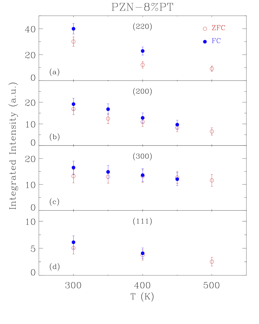
In contrast to the ZFC case, cooling in the presence of a moderate electric field ( kV/cm) oriented along the [111] direction changes the shape of the diffuse scattering dramatically (see Fig. 2). All of the linear profiles show a common feature whereby the “” wing is enhanced and the “” wing suppressed. The overall change is plotted schematically in Fig. 1 (b). This partial enhancement of the diffuse scattering intensity was first reported in Ref. Xu et al., 2005 and confirmed later by room temperature electric field measurements on single crystals of pure PZN Xu et al. (2006). In this subsection we analyze the quantitative change of the diffuse scattering induced by field cooling. The integrated intensities of the linear profiles are plotted in Fig. 3. Here the intensities of both wings are included (the numbers around the (111) peak are actually the sums of the “” wing at the (111) peak and the ” wing at the (11) peak, as was done for Table 1). We find that the -integrated diffuse intensities of both wings increase monotonically with cooling, whether ZFC or FC. The difference between the integrated intensities in the ZFC and FC cases are relatively small, considering the size of the error bars. This demonstrates that there is very likely a redistribution of the diffuse scattering intensity among the different -oriented diffuse rods, which must be associated with a redistribution of the PNR with different orientations/polarizations.
A slight enhancement of the FC linear integrated intensity compared to the ZFC case is also observed, as shown in Fig. 3. Considering previous reports of a field-induced suppression of the diffuse scattering intensities measured transverse to the Bragg wavevector in both PMN and PZN-8%PT Vakhrushev et al. (1998); Gehring et al. (2004), it is possible that the shape of each individual diffuse rod is also slightly affected by the field. Therefore measurements at different distances away from the Bragg peaks may lead to slightly different results. However, in general we find that the diffuse scattering in PZN-8%PT still consists of rods upon FC, and that the intensities are mostly redistributed between different rods, instead of within an individual rod.
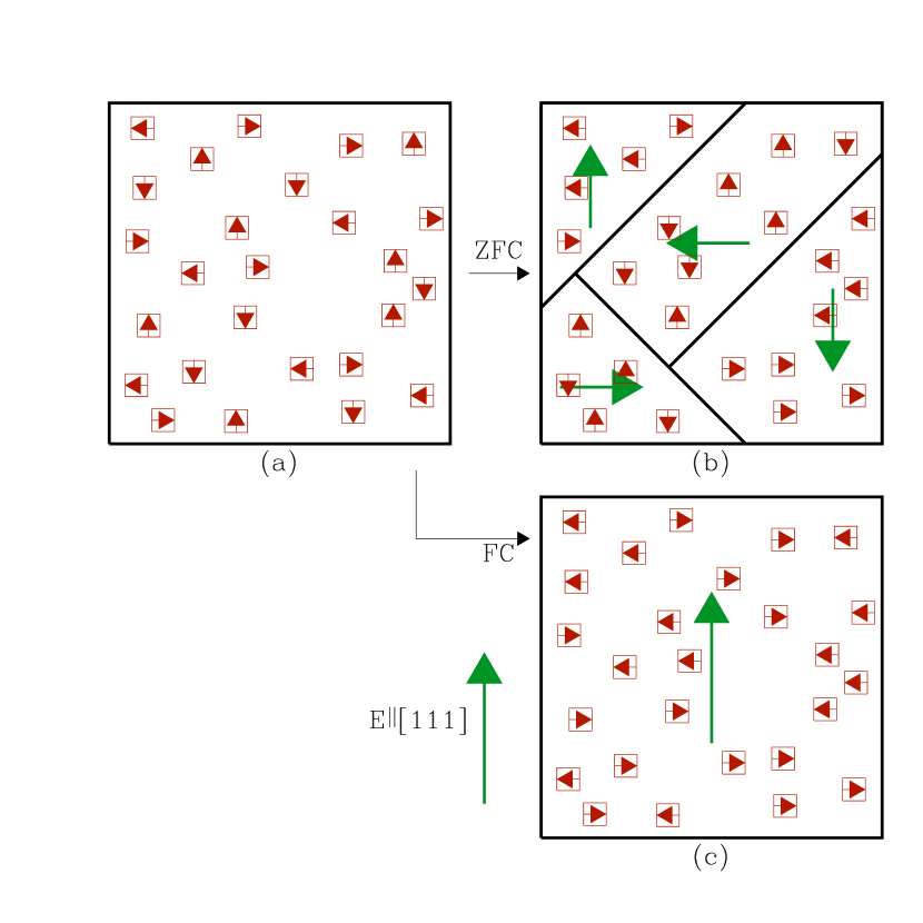
On the other hand, it is quite intriguing to note that the enhanced “” wing comes from those PNR having polarizations (along [10] and [10]) perpendicular to the [111] field direction. This goes against the natural expectation that the field should be able to “align” the PNR to point along the field direction. The same behavior was also observed in a room temperature “poling” experiment performed on a single crystal of PZN using a [111] field Xu et al. (2006). Evidently, the energy of the PNR alone in the electric field does not favor such a configuration. This suggests that the interaction between the PNR and the surrounding lattice must also be taken into account. In the paraelectric state the PNR are randomly oriented along one of six directions (see Fig. 4 (a)). Below the ferroelectric phase transition, macroscopic ferroelectric domains form and the cubic symmetry is broken. Thus PNR polarized along the six directions are no longer equivalent. After cooling in zero field the polarizations of the macroscopic ferroelectric domains are randomly distributed along any of the four directions such that there is no macroscopic preferred polarization of the PNR, as described schematically in Fig. 4 (b). However, cooling in field with E applied along [111] greatly enhances the volume of the [111] polarized ferroelectric domain (Fig. 4 (c)). Our current results are consistent with the room temperature [111] field poling measurements on PZN. Both exhibit an alignment of the ferroelectric domains, instead of the PNR themselves, due to the external electric field. Our data show that those PNR with polarizations perpendicular to the field, and therefore perpendicular to the polarization of the domain in which they reside, are enhanced. This may in fact imply that these PNR are the preferred configuration in the ferroelectric phase transition. The application of a [111] field rearranges ferroelectric domains, which in turn reveals this underlying bias of the PNR macroscopically.
IV Conclusions
Our diffuse scattering measurements on PZN-8%PT suggest that PNR persist into the low temperature ferroelectric phase under both ZFC and FC conditions. This is consistent with previous diffuse scattering measurements as well as Raman results Toulouse et al. (1992); Vugmeister et al. (1995); DiAntonio et al. (1993) obtained on other relaxor systems. We show that local atomic displacements contributing to the diffuse scattering consist of both an acoustic (strain) and optic (polar) component. This provides convincing evidence of the “polar” nature of these local orders, and stands against the argument that diffuse scatterings in relaxor systems are mainly due to local strain fields instead of local polarizations. In addition, the acoustic component, or the “Uniform Phase Shift” of the PNR increases faster than do the polarizations upon ZFC. The PNR are therefore more strongly displaced in the ferroelectric phase, causing the structure of the PNR to be more “out-of-phase” from the surrounding environment.
Our FC results reveal that the preferred configuration of the PNR in the ferroelectric phase is such that the PNR tend to align perpendicular to the polarization of the surrounding ferroelectric polar domain. This unusual configuration makes the polarization of PNR “out-of-phase” from the surrounding environment. These are probably the two most important factors that help to keep preserve the coexistence of PNR and the long range polar order in the ferroelectric phase. On the other hand, with both short-range polar order in the PNR and long-range ferroelectric order in the lattice developing at the same time (upon cooling), the strain caused by this mismatch will increase, resulting in an increase of the local strain field, which corresponds to the acoustic component of the local atomic displacements.
The coexistence of the short-range polar order of the PNR and the long range ferroelectric order of the ferroelectric phase is quite subtle. It can be affected by many factors such as electric fields - where we believe a strong enough field should be able to eventually directly affect the PNR; pressure - which appears to be able to suppress the diffuse scattering from PMN Chaabane et al. (2003) and PZN Ahart et al. (2005); and doping with PT - which eventually changes the structure of the low temperature phase and inevitably affects the PNR. These are interesting future topics that will require more detailed quantitative study, and which will be challenging and important.
Acknowledgements.
We would like to thank H. Hiraka and C. Stock, for stimulating discussions. Financial support from the U.S. Department of Energy under contract No. DE-AC02-98CH10886 is also gratefully acknowledged.References
- Park and Shrout (1997) S.-E. Park and T. R. Shrout, J. Appl. Phys. 82, 1804 (1997).
- Burns and Dacol (1983) G. Burns and F. H. Dacol, Phys. Rev. B 28, 2527 (1983).
- Cross (1987) L. E. Cross, Ferroelectrics 76, 241 (1987).
- Vakhrushev et al. (1995) S. B. Vakhrushev, A. A. Naberezhnov, N. M. Okuneva, and B. N. Savenko, Phys. Solid State 37, 1993 (1995).
- Hirota et al. (2002) K. Hirota, Z.-G. Ye, S. Wakimoto, P. M. Gehring, and G. Shirane, Phys. Rev. B 65, 104105 (2002).
- Xu et al. (2004a) G. Xu, G. Shirane, J. R. D. Copley, and P. M. Gehring, Phys. Rev. B 69, 064112 (2004a).
- Hiraka et al. (2004) H. Hiraka, S.-H. Lee, P. M. Gehring, G. Xu, and G. Shirane, Phys. Rev. B 70, 184105 (2004).
- Hlinka et al. (2003) J. Hlinka, S. Kamba, J. Petzelt, J. Kulda, C. A. Randall, and S. J. Zhang, J. Phys.: Condens. Matter 15, 4249 (2003).
- Dkhil et al. (2001) B. Dkhil, J. M. Kiat, G. Calvarin, G. Baldinozzi, S. B. Vakhrushev, and E. Suard, Phys. Rev. B 65, 024104 (2001).
- You and Zhang (1997) H. You and Q. M. Zhang, Phys. Rev. Lett. 79, 3950 (1997).
- Takesue et al. (2001) N. Takesue, Y. Fujii, and H. You, Phys. Rev. B 64, 184112 (2001).
- Jeong et al. (2005) I.-K. Jeong, T. W. Darling, J. K. Lee, T. Proffen, R. H. Heffner, J. S. Park, K. S. Hong, W. Dmowski, and T. Egami, Phys. Rev. Lett. 94, 147602 (2005).
- Xu et al. (2004b) G. Xu, Z. Zhong, H. Hiraka, and G. Shirane, Phys. Rev. B 70, 174109 (2004b).
- Stock et al. (2004) C. Stock, R. J. Birgeneau, S. Wakimoto, J. S. Gardner, W. Chen, Z.-G. Ye, and G. Shirane, Phys. Rev. B 69, 094104 (2004).
- Vakhrushev et al. (1998) S. B. Vakhrushev, A. A. Naberezhnov, N. M. Okuneva, and B. N. Savenko, Phys. Solid State 40, 1728 (1998).
- Gehring et al. (2004) P. M. Gehring, K. Ohwada, and G. Shirane, Phys. Rev. B 70, 014110 (2004).
- Xu et al. (2005) G. Xu, P. M. Gehring, and G. Shirane, Phys. Rev. B 72, 214106 (2005).
- Xu et al. (2006) G. Xu, Z. Zhong, Y. Bing, Z.-G. Ye, and G. Shirane, Nature Materials 5, 134 (2006).
- Xu et al. (2003) G. Xu, Z. Zhong, Y. Bing, Z.-G. Ye, C. Stock, and G. Shirane, Phys. Rev. B 67, 104102 (2003).
- Xu et al. (2004c) G. Xu, Z. Zhong, Y. Bing, Z.-G. Ye, C. Stock, and G. Shirane, Phys. Rev. B 70, 064107 (2004c).
- Bonneau et al. (1989) P. Bonneau, P. Garnier, E. Husson, and A. Morell, Mater. Re. Bull 24, 201 (1989).
- de Mathan et al. (1991) N. de Mathan, E. Husson, G. Calvarin, J. R. Gavarri, A. W. Hewat, and A. Morell, J. Phys. Condens. Matter 3, 8159 (1991).
- Ye et al. (2003) Z.-G. Ye, Y. Bing, J. Gao, A. A. Bokov, P. Stephens, B. Noheda, and G. Shirane, Phys. Rev. B 67, 104104 (2003).
- Kuwata et al. (1981) J. Kuwata, K. Uchino, and S. Nomura, Ferroelectrics 37, 579 (1981).
- Noheda et al. (2002) B. Noheda, D. E. Cox, G. Shirane, J. Gao, and Z.-G. Ye, Phys. Rev. B 66, 054104 (2002).
- La-Orauttapong et al. (2002) D. La-Orauttapong, B. Noheda, Z.-G. Ye, P. M. Gehring, J. Toulouse, D. E. Cox, and G. Shirane, Phys. Rev. B 65, 144101 (2002).
- Feng et al. (2004) Z. Feng, Z. Zhao, and H. Luo, J. Phys.: Condens. Matter 16, 6771 (2004).
- Ohwa et al. (2001) H. Ohwa, M. Iwata, H. Orihara, N. Ysauda, and Y. Ishibashi, J. Phys. Soc. Jpn. 70, 3149 (2001).
- (29) H. Hiraka, private communications.
- Harada et al. (1970) J. Harada, J. D. Axe, and G. Shirane, Acta Crystal. A 26, 608 (1970).
- Toulouse et al. (1992) J. Toulouse, P. DiAntonio, B. E. Vugmeister, X. M. Wang, and L. A. Knauss, Phys. Rev. Lett. 68, 232 (1992).
- Vugmeister et al. (1995) B. E. Vugmeister, P. DiAntonio, and J. Toulouse, Phys. Rev. Lett. 75, 1646 (1995).
- DiAntonio et al. (1993) P. DiAntonio, B. E. Vugmeister, J. Toulouse, and L. A. Boatner, Phys. Rev. B 47, 5629 (1993).
- Chaabane et al. (2003) B. Chaabane, J. Kreisel, B. Dkhil, P. Bouvier, and M. Mezouar, Phys. Rev. Lett. 90, 257601 (2003).
- Ahart et al. (2005) M. Ahart, R. E. Cohen, V. Struzhkin, E. Gregoryanz, D. Rytz, S. A. Prosandeev, Ho-kwang Mao, and R. J. Hemley, Phys. Rev. B 71, 144102 (2005).