Sculpting microscopic magnetic flux landscapes in a Bi2Sr2CaCu2O8+δ vortex lens
Abstract
We demonstrate experimentally that the micromagnetic profile of the out-of-plane component of magnetic induction, , in the crossing lattices regime of layered superconductors can be manipulated by varying the in-plane magnetic field, . Moving Josephson vortices drag/push pancake vortex stacks, and the magnetic profile, , can be controllably sculpted across the entire single crystal sample. Depending on the -history and temperature we can increase or decrease the flux density at the center and near the edges of the crystal by as much as 40%, realising both “convex” and “concave” magnetic flux lenses. Our experimental results are well described by molecular dynamics simulations.
pacs:
74.72.Hs, 74.25.QtIn recent years dramatic progress has been made in the control of static flux structures in superconductors by the introduction of artificial vortex pinning sites (e.g. antidots and ferromagnetic dots) baert95 ; martin97 ; morgan98 ; bael99 ; lyuksyutov98 . The next major challenge is to achieve dynamic vortex control, so that different flux profiles can be realised in the same superconducting sample. Control of vortex motion has recently been proposed vortex and demonstrated kwok-2003 ; ourscience ; moshchalkov ; togawa ; roger in so-called ratchet devices which incorporate a spatially-asymmetric ratchet potential to achieve rectification of ac drives. However, a spatially asymmetric ratchet substrate is not a fundamental requirement for ratchet operation, and recent proposals nature_materials ; prl have described novel methods to control the motion of tiny particles in a binary mixture by the dragging of one component by the other. Here we describe the first such experimental implementation of a flux lens in the binary vortex system present in highly anisotropic layered superconductors under tilted magnetic fields.
Direct visualization tonomura ; bending ; vlasko ; tamegai ; bolle91 has revealed that a tilted (away from the crystalline -axis) magnetic field penetrates the highly anisotropic Bi2Sr2CaCu2O(BSCCO) superconductor in two interpenetrating vortex arrays, known as crossing vortex lattices bul ; kosh . One vortex sublattice consists of stacks of pancake vortices (PVs) aligned along the -axis, while the other sublattice is formed by Josephson vortices (JVs) confined between CuO2 layers. Superconducting currents generated by JVs deform stacks of PVs, resulting in a mutual attraction between PVs and JVs kosh ; sav . This has been experimentally confirmed tonomura ; bending ; vlasko ; tamegai ; bolle91 by the observation of PV chains which decorate underlying JV stacks in tilted magnetic fields. JVs are usually very weakly pinned and can easily be driven by changing the in-plane magnetic field (), dragging PVs along with them icl . This joint JV-PV motion can be used to develop nature_materials vortex-pumps, vortex-diodes and vortex-lenses which have two clear advantages over other existing ratchet devices. (i) The motion of vortices can be controlled without the need for nanofabricated samples with fixed spatial asymmetry, and (ii) the focusing efficiency can be easily varied by changing either the PV density (via the corresponding magnetic field component ) and/or temperature. Here we describe how to implement such lenses experimentally.
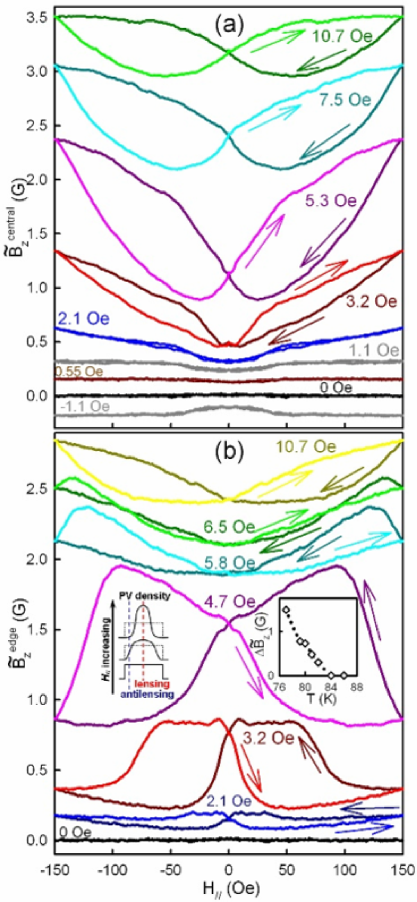
Experimental results.— Our vortex lensing experiments have been performed on an as-grown BSCCO superconducting single crystal (K, dimensions 1mm0.75mm50m). The changes in arising from PV lensing/antilensing were detected using a wirewidth micro-Hall probe array patterned in a GaAs/AlGaAs 2D electron gas array . The BSCCO single crystal was positioned directly above our sensor and secured with paraffin wax. The array has thirteen addressable elements, of which twelve were situated at different positions under the crystal and the remaining uncovered one acted as a reference. The sensor was driven by a 32 Hz ac current and the Hall voltages detected with a lock-in amplifier. The out-of-plane and in-plane magnetic field components are varied independently using a solenoid and Helmholtz coil pair (one of which could be precisely positioned vertically on a micrometer driven stage), respectively. We use the in-plane ‘lock-in’ transition kosh93 to align the in-plane field within of the ab crystallographic planes. The exact alignment position is inferred from plots of 1/ at lock-in as a function of the height of the movable Helmholtz coil, in a small fixed out-of-plane magnetic field. At the start of lensing experiments a fixed PV density was established by field-cooling the BSCCO crystal from above in a known value of the out-of-plane field, . The in-plane magnetic field was then cycled several times until a steady-state loop was obtained. During each cycle, was slowly (1.7 Oe s-1) ramped up to a maximum of 150 Oe and down to a minimum of -150 Oe and back to zero, while the Hall voltage was monitored at a chosen element to measure the magnetic induction, . In practice the observed lensing was a function of the measurement position under the crystal. For the sake of brevity we only present data here for two elements, one at the sample center and one m from one of the edges parallel to , which fully illustrate the extremes of behaviour seen. Fig. 1 shows lensing data measured (a) at the central location and (b) near the edge of the sample at 77K for different values of . In all cases the data have been symmetrized to account for a small misalignment between the plane of the BSCCO crystal and the Hall probe array. In both cases for Oe, the PV system shows a weak reversible response which inverts when is inverted, attributable to the dragging of PV stacks which are all trapped on JV chains. For 2 Oe, free PVs exist between chains (mixed chains/lattice state) and we start to see stronger, irreversible behaviour related to the compression of free PVs and their cutting through JV stacks at high in-plane fields. At higher the magnetization loop for the central element has a “butterfly” shape exhibiting: (i) a fast increase of PV density when increases from zero, followed by weaker (saturation-like) dependence of ; (ii) a rapid reduction of when decreases from its maximum value, followed by a remarkable antilensing (an overshoot in the reduction of PV density) effect . Note that on the -increasing branch of the lensing loop, is always higher than on the decreasing branch on the right-side () of the hysteresis cycle, i.e., . We denote such loops as “clockwise”.
The data from the Hall element near the sample edge (Fig. 1b) provide insights into the spatial distribution of the PV density in our lensing experiments. In stark contrast to Fig. 1a, we now see strong antilensing behaviour for Oe. This is easily understood in terms of the PV profiles generated during our experiments. Since PVs are pushed from two opposite edges of the sample towards the center, there must be regions near these edges which experience a decrease in PV density, while accumulation is occurring in the crystal center (see sketched profiles in the left hand inset of Fig. 1b). It is interesting to note that the counter-clockwise loops at low transform to clockwise ones when increases. This is best illustrated in the curve at Oe, which shows an extra crossing point for between traces on the sweep-up and sweep-down. At such high values of PVs penetrating through the sample surface partially compensate for the deficit of PVs near the edges, and enhanced PV-PV repulsion results in a broadening of the focus region and a shift of the lensing/antilensing interface towards the sample edge. Hence a transition from counter-clockwise to clockwise loops occurs as the out-of-plane field is increased. We conclude that the PV profiles, and their changes, are a subtle function of the applied out-of-plane field, allowing us to precisely control the “magnetic landscape” inside the sample. Vortex control is achieved here using just the so-called dc-driven (quasi-adiabatic) mode; ac-drives with trains of time-asymmetric pulses will be described elsewhere natmat .
The right hand insert of Fig. 1b shows a plot of the lensing amplitude at =5.3 Oe as a function of temperature. Surprisingly, we find that the lensing amplitude falls rapidly with temperature, being very weak at 84 K and undetectable at 86 K. Since this is well below the critical temperature of the BSCCO crystal ( 91K), and the crossing lattices interaction strength is only very weakly temperature dependent kosh , we conclude that efficient lensing requires finite bulk pinning to prevent PVs escaping from focus regions laterally parallel to JV stacks. The effectiveness of bulk pinning will drop rapidly at elevated temperatures leading to a rapid reduction in efficiency.
Simulations.— The minimal model to simulate the observed lensing effects describes the overdamped dynamics of JV and PV rows using a set of coupled equations of motion: , and , where and are the positions of JV and PV rows with distances between JVs(PVs) in a row () and anisotropy parameter , while and are the JV and PV viscosities. The viscous forces slowing down the vortex motion are balanced by: (1) the repulsive force between JV rows (including images of rows with respect to the sample surface); (2) the interaction of JV rows with Meissner currents generated by the externally-applied time-dependent magnetic field ; (3) the repulsion between PV rows (including images); (4) the interaction of PV rows with ; and (5) the attractive forces between rows of JVs and PVs.
The interaction between vortex rows decays exponentially sav-micro : , , where the interaction lengths are the in-plane and -axis penetration lengths, while is the relative viscosity. Hereafter, we normalize all distances by the half-width of the sample and all time scales by . The distances between PV and JV rows are related to the and magnetic field components by and . The interaction with the Meissner current decays exponentially on the scales and from the surface () of the sample, for JVs and PVs, respectively. The corresponding forces can be modelled sav-micro as and . The JV-PV attraction can be approximated as and , where is related to the tilt elasticity of PV stacks. The qualitative agreement between the very complex and nontrivial experimental data and simulations indicates that the model used captures the essential physics.
Our molecular dynamics simulations follow the experiments. First was slowly increased from zero to , and then decreased back to zero over the same period of time. Such cycles were repeated several times to achieve steady-state loops. The average PV density was monitored (as a function of ) both at the center and near the edges of the sample.
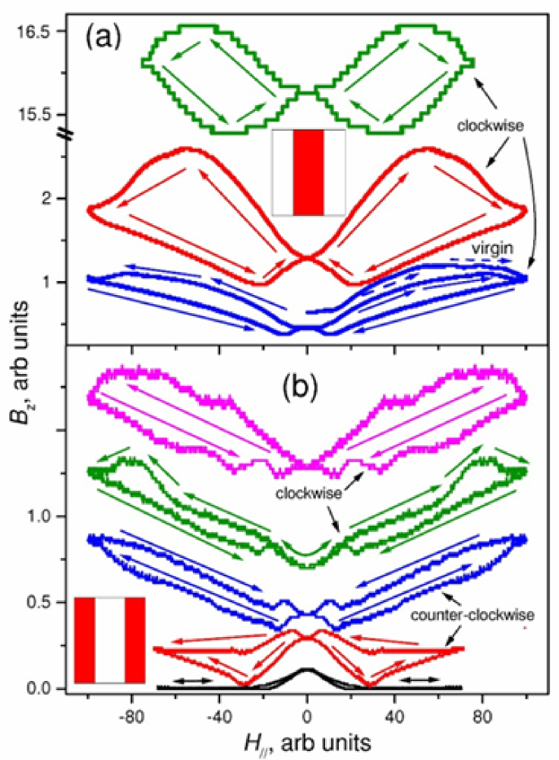
Comparison theory-experiment.— The simulated clockwise “butterfly” loops for the PV density at the center of the sample show the same features anim that were observed in experiments (c.f. Figs. 1a and 2a) and can be easily interpreted: (i) First, increases with as JVs move towards the sample center and drag PVs with them. This is consistent with theoretical predictions nature_materials ; (ii) At a certain in-plane field , the PV density at the center of the sample saturates and even starts to decrease. The PV density at the center is now large enough that PV-PV repulsion becomes very large. PVs start to cut through the JV rows and, near the maximum compression point, some of these PVs escape the narrow potential produced by the JVs and are lost; (iii) On the decreasing branch of the loop, both experiments and simulations exhibit a remarkable anti-lensing effect. This arises because a smaller total number of PVs now spreads out over the whole sample, resulting in a deficit of PVs at the center. Also the ratio of the lensing to antilensing effect, decreases to about one when the out-of-plane field increases, in agreement with experiments (this produces rounder loops for higher , see Figs. 1a, 2a).
The simulations also capture all the main features found in the experiments near the sample edge: (i) At very low out-of-plane fields, , the area of this remarkable counterclockwise loop increases with ; (ii) at higher out-of-plane fields the counterclockwise loops narrow, transform into clockwise loops and broaden again.
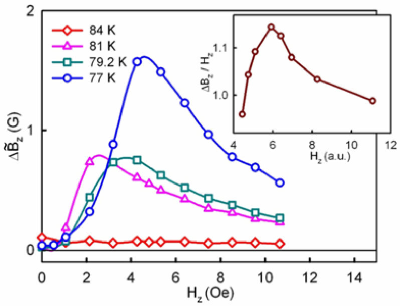
Fig. 3 illustrates the experimental (main figure) and simulated (inset) dependence of lensing amplitude on out-of-plane magnetic field. In both cases the amplitude shows a pronounced peak as a function of . At 77K the experimental lensing efficiency exhibits a maximum of nearly 40% at Oe. This field value is in reasonable agreement with the predicted maximum in JV pinning strength (by PVs) at G koshelev2003 .
Conclusions.— We have experimentally realized concave and convex magnetic vortex lenses which focus and defocus the out-of-plane magnetic flux in a Bi2Sr2CaCu2Osample. Remarkably, this was done by employing the “dragging” of PVs by JVs with no fixed spatial asymmetry in the sample. We show that the PV density near the center/edges of the sample can easily be controlled by changing either the in-plane or the out-of-plane fields, as well as by varying the temperature. The experimental results are well described by a simple model considering the dragging of one vortex species by the other. This novel method of quantum-motion-control (a ratchet with no ratchet potential) opens up new avenues for the manipulation of flux quanta and nanoscale particles.
We acknowledge support from EPSRC in the UK under grant No. GR/R46489/01, the ESF VORTEX network, the US NSA and ARDA under AFOSR contract No. F49620-02-1-0334, NSF grant No. EIA-0130383, and a Grant-in-Aid from MEXT, Japan.
References
- (1) M. Baert et al., Phys. Rev. Lett. 74, 3269 (1995).
- (2) J.I. Martin et al., Phys. Rev. Lett. 79, 1929 (1997).
- (3) D.J. Morgan et al., Phys. Rev. Lett. 80, 3614 (1998).
- (4) M.J. Van Bael et al., Phys. Rev. B 59, 14674 (1999).
- (5) I.F. Lyuksyutov et al., Phys. Rev. Lett. 81, 2344 (1998).
- (6) J.F. Wambaugh et al., Phys. Rev. Lett. 83, 5106 (1999); C. J. Olson et al., ibid 87, 177002 (2001); B.Y. Zhu et al., ibid 92, 180602 (2004).
- (7) W.K. Kwok, et al., Physica C 382, 137 (2002).
- (8) J.E. Villegas et al., Science 302, 1188 (2003).
- (9) J. Van de Vondel et al., Phys. Rev. Lett. 94, 057003 (2005).
- (10) Y. Togawa et al., Phys. Rev. Lett. 95, 087002 (2005).
- (11) R. Wördenweber et al., Phys. Rev. B 69, 184504 (2004).
- (12) S. Savel’ev and F. Nori, Nature Materials 1, 179 (2002).
- (13) S. Savel’ev et al., Phys. Rev. Lett. 92, 160602 (2004).
- (14) T. Matsuda, et al., Science 294, 2136 (2001).
- (15) A. Grigorenko et al., Nature 414, 728 (2001).
- (16) V.K. Vlasko-Vlasov et al., Phys. Rev. B 66, 014523 (2002).
- (17) M. Tokunaga et al., Phys. Rev. B 66, 060507(R) (2002).
- (18) C.A. Bolle et al., Phys. Rev. Lett. 66, 112-115 (1991).
- (19) L.N. Bulaevskii et al., Phys. Rev. B 46, 366 (1992).
- (20) A.E. Koshelev, Phys. Rev. Lett. 83, 187 (1999).
- (21) S.E. Savel’ev et al., Phys. Rev. B 64, 094521 (2001).
- (22) G.K. Perkins et al., Supercond. Sci. Technol. 18, 1290 (2005)
- (23) M.S. James et al., Phys. Rev. B 56, R5771 (1997).
- (24) A.E. Koshelev, Phys. Rev. B 48, 1180 (1993).
- (25) D. Cole et al., Nature Materials (in press).
- (26) S.E. Savel’ev, V.S. Gorbachev et al., JETP 83, 570 (1996).
- (27) Animations illustrating vortex lensing are available at http://dml.riken.go.jp/vortex-dc
- (28) A.E. Koshelev, Phys. Rev. B 68, 094520 (2003).