Theory of unconventional Smith-Purcell radiation in finite-size photonic crystals
Tetsuyuki Ochiai1 and Kazuo Ohtaka2
1Quantum Dot Research Center, National Institute for Materials Science (NIMS), Tsukuba 305-0044, Japan
2Center for Frontier Science, Chiba University, Chiba 263-8522, Japan
OCHIAI.Tetsuyuki@nims.go.jp
Abstract
Unusual emission of light, called the unconventional Smith-Purcell radiation (uSPR) in this paper, was demonstrated from an electron traveling near a finite photonic crystal (PhC) at an ultra-relativistic velocity. This phenomenon is not related to the accepted mechanism of the conventional SPR and arises because the evanescent light from the electron has such a small decay constant in the ultra-relativistic regime that it works practically as a plane-wave probe entering the PhC from one end. We analyze the dependence of the SPR spectrum on the velocity of electron and on the parity of excited photonic bands and show, for PhCs made up of a finite number of cylinders, that uSPR probes the photonic band structure very faithfully.
OCIS codes: (050.1940) Diffraction; (230.3990) Microstructure devices; (290.4210) Multiple scattering
References and links
- [1] S. J. Smith and E. M. Purcell, “Visible light from localized surface charges moving across a grating,” Phys. Rev. 92, 1069 (1953).
- [2] V. P. Shestopalov, The Smith-Purcell effect (Nova Science, New York, 1998).
- [3] J. M. Wachtel, “Free-electron lasers using the Smith-Purcell effect,” J. Appl. Phys. 50, 49–56 (1979).
- [4] D. E. Wortman, R. P. Leavitt, H. Dropkin, and C. A. Morrison, “Generation of millimeter-wave radiation by means of a Smith-Purcell free-electron laser,” Phys. Rev. A 24, 1150–1153 (1981).
- [5] A. Gover, P. Dvorkis, and U. Elisha, “Angular radiation-pattern of Smith-Purcell radiation,” J. Opt. Soc. Am. B 1, 723–728 (1984).
- [6] I. Shih, W. W. Salisbury, D. L. Masters, and D. B. Chang, “Measurements of Smith-Purcell radiation,” J. Opt. Soc. Am. B 7, 345–350 (1990).
- [7] G. Doucas, J. H. Mulvey, M. Omori, J. Walsh, and M. F. Kimmitt, “First observation of Smith-Purcell radiation from relativistic electrons,” Phys. Rev. Lett. 69, 1761–1764 (1992).
- [8] K. Ishi, Y. Shibata, T. Takahashi, S. Hasebe, M. Ikezawa, K. Takami, T. Matsuyama, K. Kobayashi, and Y. Fujita, “Observation of coherent Smith-Purcell radiation from short-bunched electrons,” Phys. Rev. E 51, R5212–R5215 (1995).
- [9] P. M. van den Berg, “Smith-Purcell radiation from a point charge moving parallel to a reflection grating,” J. Opt. Soc. Am. 63, 1588–1597 (1973).
- [10] O. Haeberlé, P. Rullhusen, J. M. Salomé, and N. Maene, “Calculations of Smith-Purcell radiation generated by electrons of 1-100 Mev,” Phys. Rev. E 49, 3340–3352 (1994).
- [11] Y. Shibata, S. Hasebe, K. Ishi, S. Ono, M. Ikezawa, T. Nakazato, M. Oyamada, S. Urasawa, T. Takahashi, T. Matsuyama, K. Kobayashi, and Y. Fujita, “Coherent Smith-Purcell radiation in the millimeter-wave region from a short-bunch beam of relativistic electrons,” Phys. Rev. E 57, 1061–1074 (1998).
- [12] J. H. Brownell, J. Walsh, and G. Doucas, “Spontaneous Smith-Purcell radiation described through induced surface currents,” Phys. Rev. E 57, 1075–1080 (1998).
- [13] R. W. Wood, “Anomalous Diffraction Gratings,” Phys. Rev. 48, 928–936 (1935).
- [14] J. B. Pendry and L. Martín-Moreno, “Energy-loss by charged-particles in complex media,” Phys. Rev. B 50, 5062–5073 (1994).
- [15] F. J. García de Abajo, “Smith-Purcell radiation emission in aligned nanoparticles,” Phys. Rev. E 61, 5743–5752 (2000).
- [16] K. Ohtaka and S. Yamaguti, “Theoretical study of the Smith-Purcell effect involving photonic crystals,” Opt. Spectrosc. 91, 477–483 (2001).
- [17] S. Yamaguti, J. Inoue, O. Haeberlé, and K. Ohtaka, “Photonic crystals versus diffraction gratings in Smith-Purcell radiation,” Phys. Rev. B 66, 195202 (2002).
- [18] F. J. García de Abajo and L. A. Blanco, “Electron energy loss and induced photon emission in photonic crystals,” Phys. Rev. B 67, 125108 (2003).
- [19] T. Ochiai and K. Ohtaka, “Relativistic electron energy loss and induced radiation emission in two-dimensional metallic photonic crystals. I. Formalism and surface plasmon polariton,” Phys. Rev. B 69, 125106 (2004).
- [20] T. Ochiai and K. Ohtaka, “Relativistic electron energy loss and induced radiation emission in two-dimensional metallic photonic crystals. II. Photonic band effects,” Phys. Rev. B 69, 125107 (2004).
- [21] K. Yamamoto, R. Sakakibara, S. Yano, Y. Segawa, Y. Shibata, K. Ishi, T. Ohsaka, T. Hara, Y. Kondo, H. Miyazaki, F. Hinode, T. Matsuyama, S. Yamaguti, and K. Ohtaka, “Observation of millimeter-wave radiation generated by the interaction between an electron beam and a photonic crystal,” Phys. Rev. E 69, 045601(R) (2004).
- [22] N. Horiuchi, T. Ochiai, J. Inoue, Y. Segawa, Y. Shibata, K. Ishi, Y. Kondo, M. Kanbe, H. Miyazaki, F. Hinode, S. Yamaguti, and K. Ohtaka, “Exotic radiation from a photonic crystal excited by an ultra-relativistic electron beam,” cond-mat/0604624.
- [23] F. J. García de Abajo, A. G. Pattantyus-Abraham, N. Zabala, A. Rivacoba, M. O. Wolf, and P. M. Echenique, “Cherenkov effect as a probe of photonic nanostructures,” Phys. Rev. Lett. 91, 143902 (2003).
- [24] F. J. García de Abajo, A. Rivacoba, N. Zabala, and P. M. Echenique, “Electron energy loss spectroscopy as a probe of two-dimensional photonic crystals,” Phys. Rev. B 68, 205105 (2003).
- [25] C. Luo, M. Ibanescu, S. G. Johnson, and J. D. Joannopoulos, “Cerenkov radiation in photonic crystals,” Science 299, 368–371 (2003).
- [26] A. S. Kesar, M. Hess, S. E. Korbly, and R. J. Temkin, “Time- and frequency-domain models for Smith-Purcell radiation from a two-dimensional charge moving above a finite length grating,” Phys. Rev. E 71, 016501 (2005).
- [27] K. Sakoda, Optical Properties of Photonic Crystals (Springer, Berlin, 2001).
- [28] K. Ohtaka, J. Inoue, and S. Yamaguti, “Derivation of the density of states of leaky photonic bands,” Phys. Rev. B 70, 035109 (2004).
- [29] V. Yannopapas, A. Modinos, and N. Stefanou, “Optical properties of metallodielectric photonic crystals,” Phys. Rev. B 60, 5359–5365 (1999).
- [30] H. van der Lem and A. Moroz, “Towards two-dimensional complete photonic bandgap structures below infrared wavelengths,” J. Opt. A 2, 395–399 (2000).
- [31] T. Ito and K. Sakoda, “Photonic bands of metallic systems. II. Features of surface plasmon polaritons,” Phys. Rev. B 64, 045117 (2001).
- [32] M. A. Kumakhov and G. Shirner, Atomic Collisions in Crystals (Gordon and Breach Science Publishers, New York, 1989).
- [33] L. D. Landau, E. M. Lifshitz, and L. P. Pitaevskii, Electrodynamics of Continuous Media, p. 408 (Butterworth-Heinemann, Oxford, 1985).
1 Introduction
A traveling charged particle induces coherent radiation when it passes near a periodic dielectric structure along the direction of its spatial periodicity. This radiation, called Smith-Purcell radiation (SPR) [1, 2], can be a novel radiation source with several remarkable properties. The most important one is the scalability of the output frequency; the threshold frequency below which SPR is kinetically impossible varies in inverse proportion to the magnitude of the period. In addition, the SPR is characterized by the presence of resonances at a series of frequencies, which again vary in inverse proportion to the period. Owing to these properties, it has been recognized that SPR can be a basic mechanism for a compact free-electron laser [3].
Since its first observation, SPR has been studied using mainly metallic diffraction gratings of one-dimensional periodicity [4, 5, 6, 7, 8]. In most theoretical analyses made so far, the gratings have been treated as perfect conductors to simplify the treatment of the periodic light scattering [9, 10, 11, 12]. In these systems, Wood’s anomaly [13] in the optical density of states (ODOS) is responsible for the enhanced signals of SPR, and thus the relevant frequencies of the resonances are determined in a straightforward manner using simple kinetics.
Recently, both theoretical [14, 15, 16, 17, 18, 19, 20] and experimental [21] SPR results have been reported for photonic crystals (PhCs) used in place of metal gratings. It was found that PhCs induced highly coherent SPR because of their multidimensional periodicity in their dielectric functions. The SPR spectrum consists of point-like signals as a function of frequency, which show up each time the evanescent light from the electron excites a photonic band (PhB) mode of high quality factor. SPR from a PhC is versatile, because PhCs generally have various parameters, which can now be reliably designed and changed.
However, when an electron beam of ultra-relativistic velocity was used in combination with a PhC, which was finite in the direction of the electron trajectory, unexpected phenomena that contradicted the conventional understanding of the SPR were experimentally observed [22]. Such phenomena have not been observed in the gratings of nearly perfect conductors and are expected to be absent even in PhCs when an electron beam of slower velocity is used. This SPR, called unconventional SPR (uSPR) in this paper, is quite distinct in many ways from the conventional SPR (cSPR) and thus is easily identified; most importantly, the uSPR spectrum sweeps the entire region of frequency-momentum phase space, in contrast to the cSPR which carries information of the phase space only along the shifted lines, to be defined later. In the phase space, the uSPR is characterized by peculiar resonances arising along curves, which are related more or less to the dispersion relations of PhBs, not to the shifted lines, with relatively little intensity variation. Therefore, SPR in the ultra-relativistic regime of the beam velocity is potentially useful both as a monochromatic light source and as a probe to investigate the PhB structure. We should note here that the Cherenkov effect also can be used to probe the PhB structure with the angle-resolved electron energy loss spectroscopy [23, 24, 25].
The conjecture inferred by the experiment, which this paper seeks to verify, was that the SPR consists of the cSPR and uSPR in the relativistic regime of electron velocity and that the uSPR is expected to disappear gradually with decreasing velocity, to leave solely the cSPR component for velocities typically less than a few hundred keV.
Very recently, Kesar et al. [26] reported a systematic discrepancy between the calculated SPR spectrum in a finite-size grating and that of the conventional theory assuming infinite size. Since they focused on the diffraction grating of a perfect conductor, their discrepancy is not directly related to ours, which arises in systems involving PhCs with a finite dielectric constant. As for this point, it is noteworthy that a rigorous theory was developed for finite-size grating of infinitely-thin metallic plates [2].
This paper presents a comprehensive theoretical analysis of the uSPR for the PhCs composed of a finite number of cylinders. We use the multiple-scattering method of theoretical treatment [19], which explicitly takes into account the finiteness of the total number of cylinders and treats exactly the multiple Mie scattering among them. We shall investigate the properties of the uSPR and the interplay between u and c SPRs by changing various parameters, such as electron velocity, dielectric constant of PhCs, length of PhCs, thickness of PhCs and angle of SPR emission. Most of this paper will focus on the PhCs of dielectric cylinders of circular cross section. The remarkable difference of the present work from the previous theoretical works involving PhCs lies in the fact that we are dealing with the finiteness of the length of PhC in the direction of the electron beam.
This paper is organized as follows. In Sec. II, we present the kinetics for both cSPR and uSPR and discuss what plays a key role in inducing uSPR. Section III is devoted to the comparison of the spectrum of uSPR with that of cSPR. In Sec. IV, we present detailed analyses of uSPR by changing various parameters. Finally, we summarize the results in Sec. V.
2 Kinetics of conventional and unconventional SPRs
In the following discussion, we focus on a PhC composed of infinitely long cylinders. The system under study is schematically illustrated in Fig. 1.
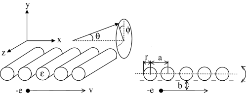
Cylinders are arrayed periodically (lattice constant: ) in the direction with cylinder axes in the direction. An electron travels near the PhC in a trajectory parallel to the axis with velocity and impact parameter . We obtain the SPR spectrum from this system as a sum of the plane-wave signals generated by the scattering of the evanescent light emitted by the electron. The whole process of multiple scattering among a finite number of cylinders is dealt with compactly by the multiple-scattering theory of radiation using the vector cylindrical waves as a basis of representation [19].
Let us briefly summarize the kinetics in the theory of cSPR. In the theory of cSPR, a finite periodic structure is simulated by a periodic structure of infinite length in the direction. A traveling electron accompanies the radiation field that is a superposition of evanescent waves with respect to frequency and wave number in the direction [16]. The wave vector of each evanescent wave is given by
| (1) |
where is purely imaginary because . The imaginary part determines the spatial decay of the evanescent wave incident on the PhC. In what follows, it is important to remember the feature of that, in the ultimate limit , tends to zero. Since and are conserved quantities in the geometry of Fig. 1, the evanescent waves with different and are independent in the whole scattering process. Thus, the incident light of and leaves the PhC, after being scattered, with the same and . Therefore, the SPR signals observed in the plane may be analyzed by setting everywhere. Since we are now dealing with a perfect periodicity extending from to , we obtain the SPR signal in the form of Bragg-scattered waves summed over the diffraction channels. The channels are specified by the wave vector defined by
| (2) |
Here, is a reciprocal lattice point of the PhC in the direction. Before the scattering by the PhC, and , the component of the wavevector of light, satisfy the relation . The line , called the line in this paper, lies outside the light cone in the phase space . After the scattering, the component of the light of channel becomes . The shifted line defined by this equation is inside the light cone in a certain frequency range. In that frequency range we can detect the SPR signal in this channel at a far-field observation point. The propagating direction of the SPR signal of is given by
| (3) |
in the polar coordinates defined in Fig. 1.
The inside region of the light cone is the leaky region of PhBs, and, accordingly, the ODOS is nontrivial there. Actually, ODOS has a sequence of peaks of finite width in the space. The peak position determines the dispersion relations of the quasi-guided PhB modes. Imagine temporarily , for brevity. The presence of the modes in the space significantly affects the SPR spectrum by causing a sharp resonance when the dispersion curves of PhBs intersect the shifted lines. The resonance becomes sharper as the quality factor of the relevant PhB modes increases [16, 17]. Therefore, the SPR from a PhC can have very high quality, which is intriguing as a new possibility of PhC.
In the above argument, we assumed the conservation of , with an Umklapp allowance taken into account. In an actual PhC with a finite number of cylinders, the periodicity or the translational invariance of the whole system is lost at the sample edges. One way to take account of the finiteness of is to treat as defined only approximately with a width of the order of [2]. In this approach, the shifted lines are considered to have the finite width, and the PhB dispersion relation will become detectable within this allowance centering on the shifted lines of open channels. In reality, however, the uSPR signals appear in the phase space with a much larger distribution than this straightforward blurring [22].
Let us now consider an ultra-relativistic velocity . We continue to confine ourselves to the measurement within the plane, i.e., . In this case, is almost zero, and the evanescent wave incident on the PhC may be regarded practically as a plane wave with its wavevector directed in the x-direction.

Therefore, the light-scattering problem is quite similar to that of the light transmission and reflection in the direction through the periodic array of cylinders, as depicted in Fig. 2. In this situation, it is obvious that the sample edges play a crucial role. In particular, we know that is no longer a good quantum number, no matter how large the total number of the cylinders may be. As in an ordinary light-transmission experiment involving PhCs, we expect the incident wave of frequency to excite the PhB modes at the crossing points between the line of constant and the dispersion curves of PhBs in the plane. The point is that the wave vector of the PhB thus determined is not related to the value of on the line of the incident light. Therefore, we should expect SPR signals over the entire space, not necessarily restricted along the shifted lines. The signals expected off the shifted lines characterize the uSPR. Also, we can expect that the transmitted SPR obtained in the side opposite to the trajectory is almost identical to the reflected SPR of the trajectory side. Finally, similar to the ordinary setup of a plane wave transmitting through a two- and three-dimensional PhC [27], a selection rule must exist for the symmetry of the PhB modes to be excited. The PhC in our problem has a symmetry with respect to the mirror reflection ( is the plane bisecting the PhC), and in the ultra-relativistic regime the incident light is of independent. Hence, solely the PhB modes of even mirror-symmetry are expected to participate in the resonant light scattering. The even-parity selection rule will thus characterize uSPR spectra.
According to this scenario, a PhB mode manifests itself in the uSPR. Therefore, the uSPR will have a rather broad band as a function of frequency. This is in contrast to the cSPR, in which excited PhB modes give rise to sharp resonance peaks only along the shifted lines. In addition, since , the shifted lines coincide with the threshold lines for the opening of a new Bragg diffraction channel. The channel opening often leaves a singular trace due to Wood’s anomaly in the line shape of wave scattering. Thus, on our shifted lines, Wood’s anomaly will occur, together with the resonance peaks of the cSPR associated with the PhB excitation. In this way, the spectra of the c and u SPRs reveal a quite rich structure when the electron is ultra-relativistic.
So far, we have concentrate ourselves on the electron traveling parallel to the direction, that is, the direction of the periodicity of the PhC under consideration. If the velocity vector of the electron is given by
| (4) |
the kinetics of SPR changes accordingly. In particular, the dominant component of wave number depends on frequency and is given by . Within the conventional theory the SPR acquires a significant enhancement when the following three conditions are fulfilled:
| (5) |
where the first equation defines the shifted line at nonzero . As in the case of , this scenario of the SPR is insufficient for an ultra-relativistic electron. In this case the evanescent wave accompanied by the electron can be effectively treated as a plane wave propagating parallel to . This highlights the role of the sample edge of the finite-size PhC, namely, the broken translational invariance, and the photonic band modes on the entire plane of are excited, not necessary restricted on the shifted lines. In the limiting case of vanishing , the electron travels parallel to the cylindrical axis. There, no propagating radiation is generated from the PhC, as far as the cylinders have infinite length in the direction. This is due to the perfect translational invariance along the axis. In actual PhC, however, this translational invariance is broken, yielding a sort of the diffraction radiation. Thus, as varies from to , the conventional theory of the SPR, which assumes the translational invariance both in the and direction, predicts a gradual disappearance of the SPR. On the other hand, the uSPR gives a novel radiation irrespective of , in which the broken translational invariance in the direction is highlighted at small , and that in the direction is highlighted around .
To summarize, the two SPR spectra, c and u SPRs, coexist in the ultra-relativistic regime, when a PhC sample is used. To analyze the experimental signals based on the knowledge on the band structure of photons, the length of the PhC or the total number of cylinders must be finite but large enough. For a finite system to have a band structure comparable to that obtained for an infinite system, the periods of, will be enough according to our experience. In contrast to the value of in the direction, however, we are considering a system having small size in the direction, such as a PhC made of a monolayer or stacked layers of several monolayers. The finite size in the direction needs to be considered explicitly to obtain the band structure of our PhCs.
3 Typical example of conventional and unconventional SPRs
Before making a detailed study of the uSPR properties, we briefly compare the cSPR spectrum with the uSPR spectrum, using the numerical results for a test system. We adopt a PhC of a monolayer of periodic array of low-index cylinders (dielectric constant ). For a radius-to-periodicity ratio , Fig. 3 depicts the band structure of the monolayer of an infinite number of cylinders.
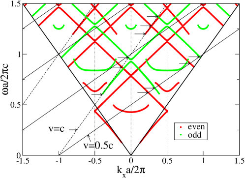
The band structure inside the light cone was obtained by plotting the peak frequencies of the ODOS, which were calculated as a function of and [28]. The band structure outside the light cone (that of the true-guided modes with infinite lifetime) was obtained from the position of the poles of the S matrix, which are found on the real axis of the complex plane. In Fig. 3, is assumed, so that the PhB modes are decomposed into purely transverse-electric (TE) and transverse-magnetic (TM) modes. Only the band structure of the TE modes is presented, because the incident evanescent wave is TE-polarized at . The PhB modes are further classified by parity with respect to the mirror plane . In Fig. 3 the even (odd) parity modes are indicated by red (green) circles. We should note that PhB modes having their dispersion curves disconnected in Fig. 3 are the ones obtained from the ODOS peaks, which are often too broad to identify the peak position.
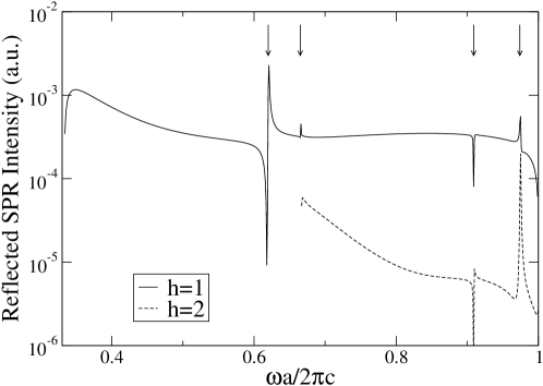
Let us first consider the cSPR spectra obtained by the conventional theory based on the assumption of perfect periodicity in the direction. We used the parameters , and and assumed that the radiation was observed in the plane , as actually encountered in the millimeter-wave SPR experiments carried out recently [21, 22]. Since the periodicity is perfect, the SPR spectrum appears strictly on the shifted lines, which are almost parallel to the light line . Figure 4 presents the reflected cSPR spectra along the shifted line of and 2 (in units of ).
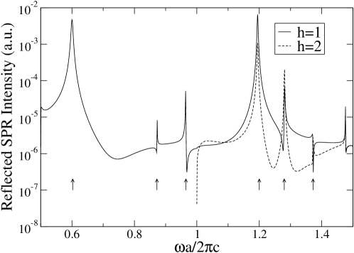
The peaks of the cSPR spectrum arise at the frequency where the shifted lines intersect the PhB structure given in Fig. 3. Several arrows are drawn at the peak positions in Fig. 4 and, to identify each of the peaks, horizontal arrows are added in Fig. 3 at the corresponding positions in phase space. Comparing these two figures, we see that the peak lowest in frequency arises from the excitation of an odd-parity PhB mode. Thus, the even selection-rule for the parity of the excited PhB modes does not hold for cSPR, though it somewhat affects their spectral shapes.
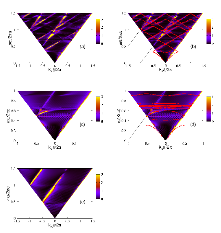
Now we turn to the uSPR spectrum. The SPR spectrum, with the finiteness of considered explicitly, is obtained over the entire space by summing all the amplitudes of the multiply scattered light from the cylinders [19]. The numerical result for is given in Fig. 5, for the same parameters of and as used in Fig. 4.
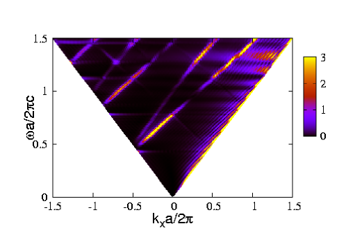
The angle - and frequency -resolved reflected SPR intensity is mapped onto the plane through the relation . To be precise, with defined in Eq. (33) of Ref. [19] was plotted by using the above relation.
We observe that the peaks of the SPR intensity are found along
(A) the shifted lines,
(B) the curves whose slopes are positive and less than 1,
(C) the curves whose slopes are negative,
(D) the forward light-line (), and
(E) the flat lines terminated on the backward light-line ().
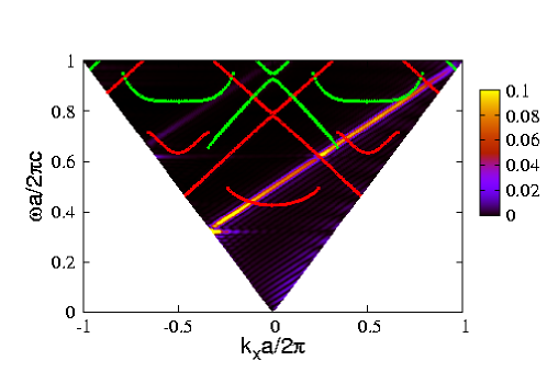
For comparison, we superimpose the even-parity PhB structure of TE modes on the intensity map and present the result in
Fig. 6.
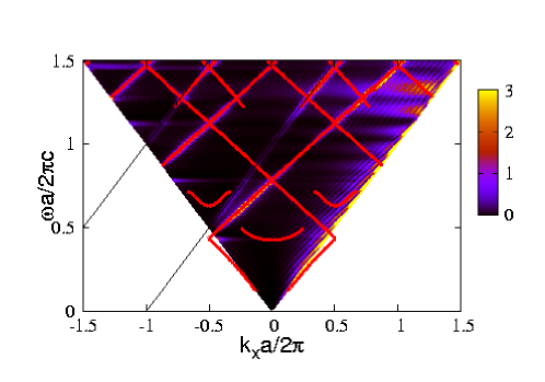
From Fig. 5, we find that type (A) peaks are rather broad along the shifted lines as a function of frequency, as compared to the cSPR spectrum shown in Fig. 4. A good agreement between the PhB dispersion curves and the high intensity positions of the uSPR demonstrates that the peaks of type (B) are attributed to the quasi-guided PhBs of even parity. Also, no evidence of the excitation of the odd-parity modes is found in Figs. 5 and 6. Thus, the even-parity selection rule of uSPR, predicted in the previous section, indeed holds. The peaks of type (C) are found, for instance, around , whose origin is also attributed to excitation of the even-parity PhB modes. The intensity of these peaks is, however, small, as compared to that caused by the PhB modes with positive slope. This seems reasonable, considering that the PhBs of the negative group velocity will have suppressed excitation probability at the left edge of the PhC. The peaks of type (D) are inevitable in finite systems; the incident wave induces the quasi-guided waves in the monolayer, which exit from the right edge, causing a forward-oriented diffraction there. As a consequence, broad peaks of the SPR near the forward light-line emerge. Note that the intensity of the type (D) signal oscillates as a function of frequency. This is a Fabry-Perot oscillation of the signal intensity with period decreasing with increasing . Finally, the signals of type (E) are caused by the presence of pseudo gaps in the PhB structure. To see this, we have only to note in Fig. 6 that the flat streaks of type (E) signals appear at the gap positions. When the frequency of the incident wave lies in a pseudo gap of the monolayer, the incident wave cannot penetrate deep inside the PhC and is scattered out of the PhC as a type (E) signal, with a certain angular distribution centering on the backward direction. Note that the intense streaks are not related to the band gaps of odd parity.
The above features of the uSPR in finite monolayers will remain unchanged even for a semi-infinite monolayer, which is made of cylinders of but bounded at one end, because what matters in the above discussion is the presence of the left edge of PhC as an entrance surface of a wave propagating in the direction.
Next, we consider SPR spectrum obtained from a slower electron in a non-relativistic regime. The calculation is made for , which is a typical value for the electron velocity used in scanning electron microscopes. The parameters except and are the same. As above, we compare two spectra of and .
First, the reflected SPR spectrum for is given in Fig. 7.
The spectra reveal a marked resonance at . The line shape of the resonance is asymmetric as a function of frequency. As indicated by arrows, each agreeing precisely with those given to the shifted line of Fig. 3, the cSPR peaks all appear exactly at the intersection points of the shifted line of with the PhB dispersion curves.
The reflected SPR spectrum for is given in Fig. 8, with the superposition of the PhB structure (of ).
We see at once that high intensity SPR appears only on the shifted lines, although very weak structures reminiscent of the finiteness of our PhC are still seen off the shifted line. This is in clear contrast to the ultra-relativistic spectra, where marked signals of uSPR existed definitely off the shifted lines. The signals on the shifted line of have a resonance peak at . This frequency is almost identical to that of the resonance obtained for shown in Fig. 7. Also, we can perceive the asymmetry of the line shape along the shifted line, as in the cSPR spectrum of . Therefore, we may conclude that, for slower velocities such as , the SPR of the finite PhC can be understood sufficiently well using the theory of cSPR, based on the assumption . The uSPR signals are suppressed as follows. The light of is literally evanescent with an appreciable decay constant , so that, while passing through the PhC in the direction, the incident light decays much and sees only the surface region of cylinders. Accordingly, the picture of a plane wave with wavevector in the direction no longer holds and the conventional theory of SPR covers all the features.
4 Properties of the unconventional SPR
This section presents the properties of uSPR in detail by changing various parameters. As explained in the previous sections, the broken translational invariance due to finite number of cylinders () is crucial in the uSPR. Taking account that the uSPR must vanish in the system of the perfect translational invariance, it is interesting to investigate the -dependence of the uSPR in detail. The number of stacking layers () is also an important factor because ODOS and thus the PhB structure depends crucially on . Dielectric constant and radius of the cylinders are other factors that significantly influence the PhB structure. However, the effects of changing are covered, to some extent, by those of . The impact parameter is not essential, as seen in the following expression for the total emission power of SPR, whose dependence is collected into a simple scaling law [19]
| (6) | |||
| (7) |
where is the - and -resolved emission power for an impact parameter and is a reference impact parameter chosen arbitrarily. Therefore, uSPR and cSPR change in a straightforward way as varies, with the underlying physics unaltered. In the following subsections, therefore, five parameters, , and , are varied in this order to see how each affects the spectrum.
4.1 Velocity
The velocity of the electron beam is a key parameter in the uSPR. Indeed, as seen in the previous section, the SPR at is understood using the theory of cSPR, while at the uSPR also plays an important role. We shall examine how the conventional picture fails with varying electron velocity. An obvious but nonessential -dependence is an increase of the SPR intensity due to the dependence of the decay-constant ; if impact parameter is fixed, the overall SPR spectrum behaves as . To eliminate this trivial -dependence, we have set
| (8) |
considering for .
The reflected intensity maps for the monolayer of are shown in Figs. 9 (a) and (b) for and in (c) and (d) for , along with the PhB structure.
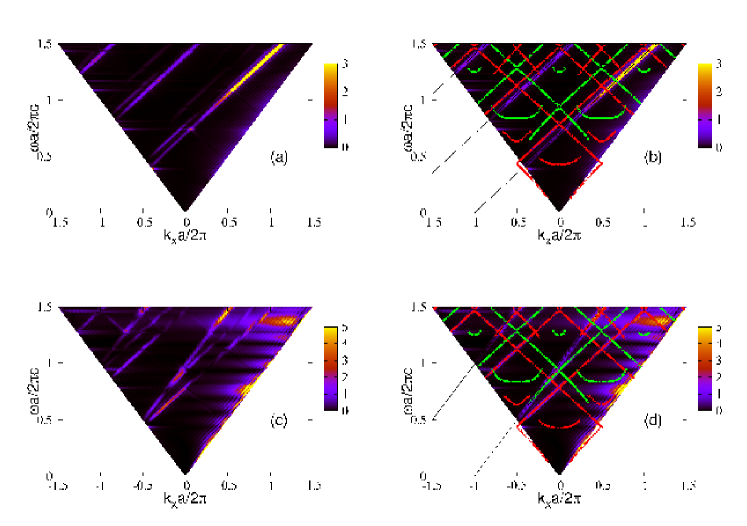
Panels (a) and (c) show only the SPR intensity, while they are superposed by the PhB structure in panels (b) and (d).
At , there is a marked bright line along the shifted line of . Along the line, the intensity contrast of the SPR is quite strong at low frequencies. In particular a point-like resonance is seen at . As panel (b) shows, this resonance arises just at a crossing between the dispersion curve of an even-parity PhB and the shifted line of . Therefore, this is a type (A) signal according to the classification of the last section.
We can see the flat streaks of strong intensity just at this frequency,. We note that the signal becomes stronger as approaches the backward light line . This feature is common to all the horizontal streaks appearing at the frequencies of the pseudo gaps. These are signals of type (E) of the uSPR. We should note that the PhB mode, which crosses the shifted lines, has a negative group velocity, and the excited PhB mode propagates in the direction. A backward-oriented diffraction taking place at the left edge of the PhC explains the tendency towards the line . Analogous flat lines exist, for instance, at .
In addition, we see clearly a high-intensity spectrum appearing almost parallel to the shifted lines. The curves are in fact coincident with the dispersion curves of quasi-guided PhB of the even parity. Therefore, they are type (B) signals. Note that the odd-parity PhB dispersion curves are also visible, with reduced strength as compared to the even-parity PhBs. Altogether, at , cSPR coexists with uSPR and odd-parity PhBs are seen in the uSPR spectrum, with weaker intensity than even-parity PhBs, however. Combining this result with what we have seen in Sec. III for and , we may conclude that, as increases from , the uSPR becomes visible and the even-parity selection rule of uSPR is less stringent at non-ultra-relativistic velocities.
The result for indeed confirms this conclusion. At , several bright curves arise in Figs. 9 (c) and (d) with little intensity contrast along the PhB dispersion curves. This is the type (B) signal. We can observe odd-parity excitation of weak intensity. Therefore, although the even-parity selection rule is indeed dominant, it is somewhat relaxed for . On the shifted line, there are signals of cSPR, as theory predicted for type (A) features in Sec. III.
The breakdown of the even-parity selection rule at these velocities is explained as follows. With a decrease of , increases to make the incident evanescent light decay more quickly when passing the monolayer. This increases the asymmetry of the evanescent wave with respect to the mirror plane and makes the even-parity selection rule less effective. The degree of the symmetry of the input wave may be given by the factor , called here the symmetry factor, which measures the decay of the evanescent wave while traversing the PhC in the direction. If this factor is unity, the evanescent light seen by the PhC is mirror-symmetric. At , the symmetry factor is 0.408 at and too small to guarantee strictly the even-parity selection rule. Therefore, odd-parity PhBs are allowed somewhat as uSPR signals.
The results for the other are briefly summarized without giving numerical results. At , when the symmetry factor is 0.047, cSPR and uSPR coexist and odd-parity PhBs are seen in the latter. At , the asymmetry factor increases to 0.755. The intensity map gradually tends to the case of with the symmetry factor 0.972; signals along the odd-parity PhBs disappear, leaving behind only the even-parity signals as type (B) signals. The horizontal bright streaks appear solely in the regions of the pseudo-gaps of even-parity bands.
Finally, we should comment on the case of non-zero . The critical velocity of the electron, above which the uSPR begins to emerge does not change so much by non-zero . An important point is that at ultra-relativistic velocities the evanescent wave can be effectively regarded as a plane wave. This is not controlled by , but is controlled by , the magnitude of the velocity vector. However, other features of the uSPR changes as discussed in the previous section.
In conclusion, in the frequency region , the uSPR is conspicuous when exceeds 0.7c, and the even-parity selection rule holds progressively better as approaches from .
4.2 Dielectric constant
For a PhC with and kept fixed at and , let us examine how the SPR spectrum varies as the dielectric constant of the cylinders changes in the monolayer. We select three values of , and . The first case corresponds to the dielectric constant of fused quartz with nearly twice as large as that used above, the second is the dielectric constant of a Drude metal with the plasma frequency, and the third is the dielectric constant of a perfect conductor. To avoid the poor convergence of the cylindrical-wave expansion for the metallic cylinders in contact, we created a narrow opening between the cylinders by setting in the Drude case. We assumed , i.e., the plasma wavelength equals the lattice constant. Calculation is made for the monolayer system using and , as before.
The reflected SPR intensity maps are shown in Fig. 10, together with the corresponding PhB structure obtained for the system.
Panels (a) and (b) depict the result of dielectric cylinders, panels (c) and (d) treat the Drude cylinders, and panel (e) presents the spectrum of the cylinders of a perfect conductor. Panels (b) and (d) also involve the band structures of the monolayer. Considering is ultra-relativistic, we only plotted the even-parity PhB structure. Note that for the perfect conductor case of panel (e), the ODOS does not present any peaks except for Wood’s anomaly and the PhB structure is completely absent.
Clearly, the calculated uSPR intensity shown in panels (a) and (b) is well correlated with the PhB structure. Namely, the bright curves of strong SPR intensity are type (B) signals having a positive slope and tracing very well the even-parity PhB dispersion curves. In addition, we can recognize type (E) signals of the bright flat lines terminated at the backward light line, which are seen just at the frequencies of the pseudo-gaps. These features agree with what we have seen in Sec. III. Most importantly, the PhB structure with larger dielectric constant is indeed probed by the uSPR.
As for the Drude case shown in panels (c) and (d), the PhB structure is composed of many flat bands. These PhB modes have their origin in the tight-binding coupling among cylinders of the surface plasmon polaritons (SPP), localized on each cylinder surface [29, 30, 31]. The calculated intensity map demonstrates that these SPP bands are coupled only weakly to the incoming evanescent wave. In contrast, the PhB around , which has a modest group velocity, is strongly coupled to the evanescent wave, yielding a very strong SPR signal. We thus conclude that uSPR carries information of PhBs of SPP origin.
Finally, in Fig. 10(e) the strong intensity of the SPR arises solely on the shifted lines. This reflects the absence of the PhB structure in the array of perfect-conductor cylinders. Thus, we can conclude that the uSPR is peculiar to dielectric and metallic PhCs with finite dielectric function and is completely absent in the systems without PhBs.
4.3 Number of cylinders
In the numerical results shown so far, the number of the cylinders is fixed at either or . At small , typically less than 8, the PhB structure is not clearly visible in the intensity map of the SPR on the plane. On the other hand, at large the PhB structure is clearly visible as demonstrated in Figs. 5 and 6. In this region, however, change of the SPR intensity map with increasing is less remarkable. Nevertheless, if we have a close look at the spectral line shapes of the uSPR, they indeed change with . To investigate this feature, we consider the SPR spectra at a fixed solid angle as a function of frequency. Figure 11 shows the spectra for various .
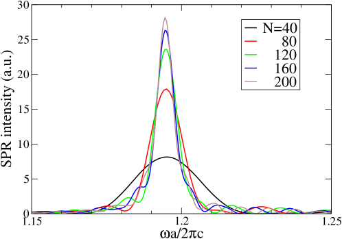
The SPR signals are strongly enhanced around , which corresponds to an intersection point between the line of (see Eq. (3)) and the PhB structure . The intersection point is off the shifted lines and thus is indeed an uSPR signal. We can clearly observe that as increases, the intensity at the peak grows but seems to be saturated to a certain value. This implies that the radiation intensity of the uSPR per unit length of the electron trajectory decreases at large and eventually vanishes at . This property is reasonable because the uSPR is completely forbidden in the system of perfect translational invariance with . On the other hand, we also found that the intensity of the cSPR on the shifted lines increases almost linearly with , as expected from the conventional theory of the SPR. Therefore, at very large the cSPR signals will dominate over the uSPR ones. However, even at we found that the SPR intensity map does not differ so much from Fig. 5, in which the uSPR signals are rather stronger than the cSPR ones. Besides, in Fig. 11 we can clearly observe that the spectral width of the peak decreases with increasing . This property reflects better confinement of the radiation energy for larger . This width should converge to a certain value at , which is inversely proportional to the life-time of the relevant photonic band mode. This is nothing but the homogeneous broadening of the spectral line width of the uSPR.
4.4 Number of stacking layers
So far we have confined ourselves to the monolayer PhC. Now let us stack the identical monolayers periodically in the direction. As we increase the number of the stacking layers, the ODOS reveals a progressively finer structure as a function of frequency. Each peak of ODOS corresponds to a quasi-guided PhB mode confined in the stacked layers. The typical peak-to-peak distance in frequency is inversely proportional to . Moreover, each peak is generally getting sharper.
If is large enough, the scattering of the evanescent wave in the ultra-relativistic regime is identical to the transmission and reflection of a TE-polarized plane wave that enters the PhC with its left edge as an entrance surface. The slab PhC in question has a finite thickness in the direction and has a large extension in the direction with the entrance surface parallel to the plane. The wave vector component parallel to the entrance surface is conserved, and the incident plane wave excites the bulk PhB modes having the same . There is no momentum conservation in the component; in principle the light excites any PhB modes of arbitrary . The scattered wave is decomposed into diffraction channels [27].
Let us examine the stacked monolayers with a square lattice of the cylinders. For uSPR, plays the role of in the above analogy, and thus we may set in the ultra-relativistic case, provided . Accordingly, the incident plane wave has the wave vectors and propagates in the direction of the square lattice. The bulk PhB modes along are thus excited. The conclusion is thus that uSPR will carry information along of the bulk PhB modes if both and are sufficiently large. According to the above arguments, the SPR intensity is expected to be enhanced in the forward and backward directions, which correspond to the specular transmission and reflection. In addition, if , the SPR intensity is expected to be enhanced also on the curves
| (9) |
which correspond to the diffraction channels associated with the reciprocal lattice points along the axis.
Figure 12 illustrates the reflected SPR intensity maps and the relevant PhB structure of low-index cylinders in contact. We used , and .
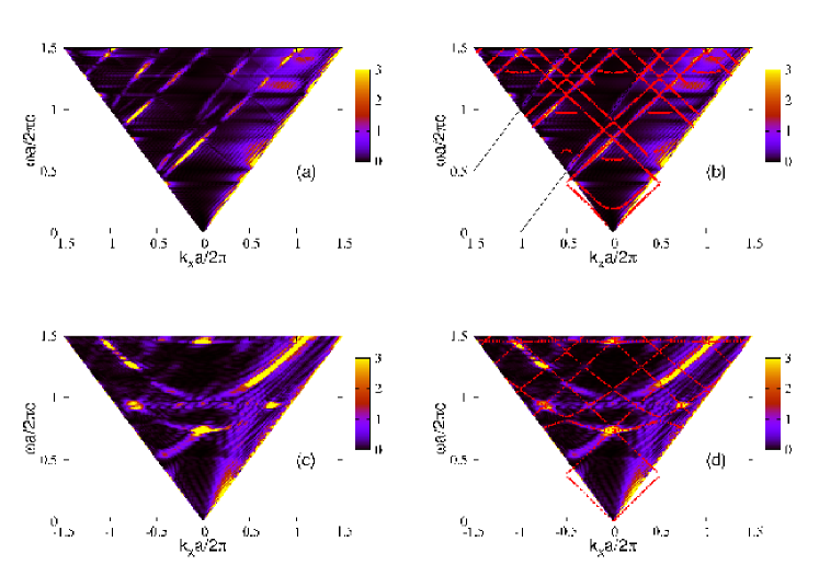
In Fig. 12(a) the spectrum from the double-layer () structure with is shown. The intensity map overlaid with the PhB structure of the double layers (but for ) is shown in panel (b). As before, we plotted only the even-parity PhB structure. In the double layer, the mirror plane lies midway between the layers. We see the number of bands is almost twice that of the monolayer band structure shown in Fig. 3. This is reasonable, since the degenerate band-structures of each of the monolayers are split in the double layer. Obviously there is a very good correlation of the strong signals of uSPR with the band structure of the even parity.
Figure 12(c) shows the reflected intensity map of the finite multilayers PhC of and . We consider this to be a test system simulating the slab-type PhC of square lattices. We observe at once a signal of high intensity along a hyperbolic curve whose bottom is found at . Obviously, this curve corresponds to Eq. (9) with . Strong SPR signals other than the hyperbolic curve are found at , 0.93, and 1.46. To identify these signals, Fig. 12(c) was overlaid with the even-parity PhB structure along the direction of the square lattice. The result is shown in Fig. 12(d). As can be clearly seen, the strong signals correspond to the anti-crossing points of the even-parity PhB structure. The bright curve connected to the strong signal around is shown to be along the PhB dispersion curve. Thus, we can conclude that the intensity map of the uSPR correlates well with the corresponding PhB structure even in the case of stacked monolayers.
4.5 Azimuthal angle
So far, we have considered the case of ( and ), that is, we have examined the radiation emitted within the plane. We here investigate the dependence. For this purpose, we write the differential cross section of SPR in polar coordinates [19]
| (10) | |||
| (11) | |||
| (12) |
Obviously, the cross section must have inversion symmetry under the operation , reflecting the inversion symmetry of the coordinate with respect to the electron trajectory located at .
The radiation emission of non-vanishing is generally small compared with that of , and is a conserved quantity in the scattering by the PhC. Therefore, the dependence of the observed SPR will be controlled dominantly by that of the decaying exponential of the initial light. This exponential decreases with increasing , so that the radiation is dominated by the SPR of .
Let us consider the radiation emission toward solid angle . In the ultra-relativistic regime it follows that
| (13) |
Thus, the SPR cross section at a given and is dominated in the forward () and backward () directions. Similarly, at a given , the SPR cross section is dominated around the plane perpendicular ( and ) to the cylindrical axis.
Figure 13(a) projects the reflected SPR spectrum Eq. (10) for onto the plane, and Fig. 13 (b) projects the reflected SPR spectrum for is projected onto the plane.
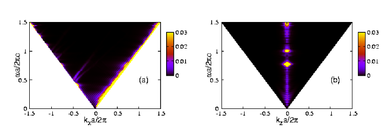
Figure 13(a) verifies that the strong intensity is limited around the forward and backward light lines, as asserted above. The intensity contrast along the backward light line is related to the PhB structure with finite . In Fig. 13(b), the strong SPR intensity is limited around . At , three marked peaks can be found at and 1.5. They correspond to the crossing points between the bright curves of Fig. 5 and the line of (i.e., ). Thus, we can conclude that SPR is highly directive within the plane normal to the cylindrical axis.
5 Summary and discussions
To summarize, we have presented a theory of uSPR that arises when an ultra-relativistic electron beam is used to obtain the SPR from a finite PhC composed of cylinders. The ultra-relativistic electron accompanies an evanescent wave whose spatial decay is almost negligible at , so that the evanescent wave can be regarded as a plane wave propagating in the direction of the trajectory. This yields a peculiar radiation emission from the PhCs, which cannot be explained by the conventional theory of the SPR in which the finiteness of PhC is treated as infinite. The spectrum of the uSPR can be used as a probe of the PhB structure of the quasi-guided modes having the even-parity symmetry with respect to the relevant mirror plane.
We have also presented properties of the uSPR in detail by changing several system parameters. We found that the uSPR coexists with the cSPR at moderate velocities typically in between and . We also found that the uSPR is completely absent in the perfect-conductor cylinders because of the absence of PhBs. Otherwise, the spectra of the uSPR correlate with the corresponding PhB structure very well. We also found that the cross section of the SPR at an ultra-relativistic velocity is highly directive within the plane normal to the cylindrical axis.
It should be emphasized again that the uSPR is an unexpected phenomenon, in which the conventional theory assuming infinite periodicity of the PhCs fails to reproduce its features. On the other hand, the present theory explains very well both the c and u SPRs in a unified manner. There are three key items in the uSPR: presence of PhBs, broken translational invariance of PhC, and ultra-relativistic velocity of the electron beam. Lack of either one of the three items prevents understanding of the uSPR correctly.
In actual PhCs various types of disorder or randomness are inevitable, yielding the inhomogeneous broadening of spectral line width of the SPR. For instance, a rigid vibration of constituent cylinders of the PhC gives rise to the Brillouin scattering. As a result, the broadening of the line width is given by the frequency of the vibration. The relative percentages of various disorder factors depend crucially on the frequency range concerned. Thus, when we extract the intrinsic SPR signals from PhC, we should carefully take account of disorder.
From the point of view of the radiation emission from high-energy electron interacting with periodic structure, we should comment on the peculiarity of the uSPR in comparison to the channeling radiation, or in other words, Kumakhov radiation [32]. The latter radiation occurs inside a crystal when a certain condition is satisfied for the incident angle of the electron with respect to a major crystal direction. The radiation depends strongly on the meandering trajectory of the electron trapped around a crystal plane or a crystal axis and has a monotonic frequency. On the other hand, the uSPR does not require the meandering of the electron trajectory. Actually, in our theoretical approach, the trajectory of the electron is assumed to be straight. In addition, the radiation spectrum of the uSPR is not monotonic for a fixed trajectory and the typical frequency range is inversely proportional to the lattice constant of the PhC under consideration. Therefore, the uSPR is not categorized into the channeling radiation.
The uSPR is, in some sense, similar to the transition radiation [33] because the broken translational invariance along the electron trajectory is crucial in both the radiations. However, there is a marked difference in the directivity between the transition radiation and the uSPR. Suppose that an ultra-relativistic electron passes from vacuum to a dielectric medium. It is better to focus on the radiation into the vacuum side, because the induced radiation in the medium is a mixture of the transition radiation and the Cherenkov radiation. It was shown that this radiation into the vacuum side is backward-oriented. On the other hand, as we showed in the paper, such a high directivity into the backward direction is only possible if the relevant frequency lies in a pseudo gap of the PhB structure. Among other electron-induced radiations, the uSPR may have the closest resemblance to the diffraction radiation regarding the broken translational invariance and the trajectory which does not pass through any air/dielectric interfaces. To further clarify the resemblance, a detailed investigation of the diffraction radiation in PhC is in order.
Acknowledgments
The authors would like to thank N. Horiuchi, J. Inoue, Y. Segawa, Y. Shibata, K. Ishi, Y. Kondo, H. Miyazaki, and S. Yamaguti for valuable discussions. This work was supported by Grant-in-Aid (No. 18656022 for T. O. and No. 17540290 for K. O.) for Scientific Research from the Ministry of Education, Culture, Sports, Science and Technology.