Impact of the transport supercurrent on the density of states in the weak link
Abstract
The impact of the transport supercurrent on the quasiparticle density of states in the superconducting thin film with the weak link is investigated. At the weak link the order parameter is locally suppressed due to the order parameter phase difference . This results in the appearance of the zero-energy states, which are strongly influenced by the supercurrent especially at close to . The subgap density of states, dependent on both the supercurrent and the phase difference, is shown to modify the conductance characteristics of the structure.
pacs:
74.50.+r, 74.45.+c, 74.78.NaProperties of a mesoscopic superconductor are defined by its local density of states (LDoS). At the interface LDoS can be probed with the tunneling spectroscopy Duke . Particularly interesting are situations when there are states (so-called midgap states) within the bulk amplitude value of the order parameter , that is at the quasiparticle energy . This situation is ubiquitous in unconventional superconductors, where an interface results in the local suppression of the order parameter (due to its anisotropy) and in the appearance of the zero-energy states Hu . These zero-energy states are responsible for several interesting phenomena. First, when there is either external magnetic field or supercurrent injected, these midgap states create the countercurrent, which counterflows to the diamagnetic current in the former case, leading to the paramagnetic response FRS97 ; Higashitani , or counterflows to the injected supercurrent in the latter case KOSh2 . Second, when LDoS is probed with the tunneling spectroscopy, they result in the zero-bias conductance peak FRS97 ; Tanaka .
A weak link between two banks of conventional superconductors is similar to an interface of an unconventional superconductor in this context of local suppression of the order parameter KO and of the creation of the midgap states Furusaki . In recent years impact of the supercurrent on the density of states, and in particular, on the midgap states, has attracted the renewed attention (see e.g. Refs. Sanchez ; Anthore ; Zhang ; canadci ). In Refs. KOSh1 we have studied first of the above mentioned effects in the weak link between current-carrying superconductors. And in this paper we address the second problem of the appearance of the midgap states at the weak link between two current-carrying conventional superconductors. This subject is interesting both for further understanding of interference effects in mesoscopic superconducting structures and for possible applications for electronic devices, in which the current can be strongly controlled either electrodynamically (creating order parameter phase difference) or thermodynamically (injecting transport current) otherpropos . In what follows we describe the model system to study the midgap states at the weak link between two current-carrying conventional superconductors.
We consider the superconducting film with the impenetrable partition along -axis, shown with the thick line in Fig. 1.
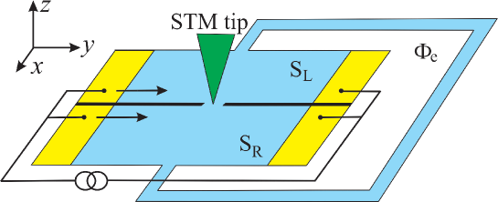
This partition (which can be e.g. a scratch in the film) has a break, which plays the role of the weak link in the form of a slit between two superconducting banks and . The size of the weak link is assumed to be smaller than the coherence length (so-called pinhole model). The order parameter phase difference at the weak link is created by the magnetic flux which pierces the loop connecting two banks. The magnetic flux can be created e.g. via the inductive coupling to a current-carrying coil. The supercurrent, tangential to the boundary between the banks and , is passed through the contacts, as in Ref. canadci . The LDoS is assumed to be probed by the scanning tunneling microscope’s (STM) tip, placed over the weak link. Another contact for STM is not shown in Fig. 1 and we refer the reader to Ref. canadci where both the current injection and the STM measurement as in Fig. 1 are discussed in detail.
Thus, we consider a perfect point contact between two clean current-carrying singlet superconductors. The order parameter phase difference is assumed to drop at the contact plane at . The homogeneous supercurrent flows in the banks of the contact along the -axis, parallel to the boundary. The sample is assumed to be smaller than the London penetration depth so that the externally injected transport supercurrent can indeed be treated as homogeneous far from the weak link. Such a system can be quantitatively described by the Eilenberger equations. Taking transport supercurrent into account leads to the Doppler shift of the energy variable by , where is the Fermi momentum and is the superfluid velocity. The standard procedure of matching the solutions of the bulk Eilenberger equations at the boundary gives the Matsubara Green’s function at the contact at KOSh2 . The analytic continuation () of the component of gives the retarded Green’s function, which defines LDoS at the boundary:
| (1) |
| (2) |
| (3) |
here are Matsubara frequencies, is the relaxation rate in the excitation spectrum of the superconductor, is the angle-resolved DoS, is the density of states at the Fermi level, denotes averaging over the directions of Fermi momentum , stands for the order parameter in the left (right) bank, , . The poles of the retarded Green’s function define the energy of the interface bound states. The direction-dependent Doppler shift results in the modification of LDoS as it is discussed below.
The method of the tunneling spectroscopy allows to access the LDoS by measuring the tunneling conductance of the Superconductor - Insulating barrier - Normal metal (STM tip) structure. At zero temperature the dependence of the conductance on the bias voltage is given by Duke
where is the conductance in the normal state; is the angle-dependent Superconductor-Insulator-Normal metal barrier transmission probability. The barrier can be modelled e.g. as in Ref. FRS97 with the uniform probability within the acceptance cone , where is the polar angle and the small value of describes the thick tunneling barrier. In this paper for simplicity we do not take into account the angle dependence of the transmission probability, assuming that the conductance is proportional to the LDoS: .
In the case of a weak link in the form of a constriction between two conventional superconductors with KOSh1 Eq. (3) can be rewritten:
| (4) |
where is the locally suppressed order parameter (so-called proximity gap) KO . The retarded Green’s function, determined with Eqs. (2) and (4), gives for the energy of the Andreev bound states: . Thus, there are the zero energy states, which are characterized by the values and . The observation of the conductance characteristics of the system can be proposed as a test of the interface-induced transport-current-dependent quasiparticle states FRS97 ; Furusaki ; KOSh1 .
For the sake of generality we also write down below the Green’s function for the current-carrying -wave superconductor. This can be easily done in the case of the specular reflection at the boundary, when the boundary between the current-carrying -wave superconductor and the insulator can be modelled as the contact between two superconductors with the order parameters given by and and with . Then from Eq. (3) we have the following expression, which together with Eq. (1) describes the LDoS in the current-carrying -wave film as e.g. in Refs. FRS97 ; canadci :
| (5) |
where and . This expression is valid for any relative angle between the -axis and the normal to the boundary; in particular, at we have: , and at we have: . Analogously Eq. (3) can be used to describe the LDoS at the boundary between two current-carrying -wave superconductors as in Fig. 1 (see also in Ref. KOSh2 ).
In what follows we consider the LDoS at the point contact between current-carrying conventional superconductors in details first analytically at and then numerically for .
In the absence of impurities, that is in the limit , we obtain the LDoS depending on the energy and on the parameters and :
| (6) |
where and are the theta- and delta- functions; ; . This after integration results in:
Here ; the first term describes the LDoS related to the continuum states, which coincides with the LDoS in the current-carrying homogeneous thin film Fulde , and the second term gives the contribution of the bound states.
Results of the numerical calculation at non-zero relaxation rate are presented in Fig. 2.
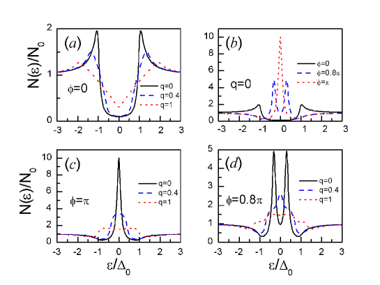
First, LDoS in the homogeneous current state (that is at ) is shown in Fig. 2(a) to experience the suppression of the peak at and gradual appearance of the midgap states with increasing the transport supercurrent Fulde . Then LDoS in the point contact without the supercurrent () is plotted in Fig.2(b). With increasing the phase difference from to the peak is shifted from to . Note that the peak at would appear as the so-called zero-bias conductance peak (ZBCP) in the STM measurements (see also in Ref. Amin about the appearance of ZBCP in point-contact Josephson junctions with ac biasing voltage). In Fig. 2(c) it is shown that the supercurrent results in the suppression and widening of this ZBCP similar to the ZBCP suppression in d-wave superconductor canadci . Note that in concrete realizations the details of the modification of the ZBCP (widening, splitting) depend on several parameters, such as barrier anisotropy, surface roughness FRS97 ; canadci ; Aubin . And finally in Fig. 2(d) we study the situation when the order parameter at the contact is significantly suppressed due to the phase difference at close to . In the absence of the supercurrent there are two midgap peaks (see also in Fig. 2(b)). With the gradual increase of the supercurrent these two peaks are shifted and modified so that first three-humped and then four-humped midgap structures appear, which are shown respectively for and for . Similar humped structure of LDoS in homogeneous current-carrying superconductor (i.e. at ) was studied in Ref. Zhang . In the homogeneous situation, studied in Ref. Zhang , the particularly interesting zero-energy states (which appear as ZBCP) take place when the supercurrent is strong enough to depair electrons but smaller than the thermodynamic critical current, that is in rather narrow region: . We emphasize that in our case when the order parameter is locally suppressed (controlled) by the phase difference, the ZBCP appears at any value of the supercurrent at the phase difference defined by the relation (see Figs. 2(b) and (d)).
In conclusion, LDoS at the weak link between current-carrying superconductors have been studied. We propose this LDoS to be visualized with the STM. Two controlling mechanisms - external magnetic flux and injected supercurrent - allow to vary LDoS, and correspondingly the characteristics of the structure in different ways in the wide range of the parameters and .
The author is grateful to A.N. Omelyanchouk, Yu.A. Kolesnichenko, and M. Grajcar for helpful discussions. This work was partly supported by grant of President of Ukraine (No. GP/P11/13).
References
- (1) C. Duke, Tunneling in solids, Academic Press, NY (1969).
- (2) C.-R. Hu, Phys. Rev. Lett. 72, 1526 (1994).
- (3) M. Fogelström, D. Rainer, and J.A. Sauls, Phys. Rev. Lett. 79, 281 (1997).
- (4) S. Higashitani, J. Phys. Soc. Jpn. 66, 2556 (1997).
- (5) Yu.A. Kolesnichenko, A.N. Omelyanchouk, and S.N. Shevchenko, Low Temp. Phys. 30, 213 (2004).
- (6) Y. Tanaka and S. Kashiwaya, Phys. Rev. Lett. 74, 3451 (1995).
- (7) I.O. Kulik and A.N. Omelyanchouk, Sov. J. Low Temp. Phys. 4, 142 (1978).
- (8) A. Furusaki, Superlatt. and Microstr. 25, 809 (1999); A. Furusaki and M. Tsukada, Phys. Rev. B 43, 10164 (1991).
- (9) J. Ferrer, M.A. Gonzalez-Alvarez, and J. Sanchez-Canizares, Superlatt. and Microstr. 25, 1125 (1999).
- (10) A. Anthore, H. Pothier, and D. Esteve, Phys. Rev. Lett. 90, 127001 (2003).
- (11) D. Zhang, C.S. Ting, and C.-R. Hu, Phys. Rev. B 70, 172508 (2004).
- (12) J. Ngai, P. Morales, and J.Y.T. Wei, Phys. Rev. B 72, 054513 (2005).
- (13) Yu.A. Kolesnichenko, A.N. Omelyanchouk, and S.N. Shevchenko, Phys. Rev. B 67, 172504 (2003); S.N. Shevchenko, in Realizing Controllable Quantum States - In the Light of Quantum Computation, Proc. Int. Symp. on Mesoscopic Superconductivity and Spintronics, Atsugi, Japan, eds. H. Takayanagi and J. Nitta (World Scientific, Singapore, 2005), p. 105; arXiv:cond-mat/0404738.
- (14) G. Wendin, V.S. Shumeiko, and P. Samuelsson, Superlatt. and Microstr. 25, 983 (1999); A.A. Golubov et al., ibid. 25, 1033 (1999).
- (15) P. Fulde in Tunneling Phenomena in Solids, ed. by E. Burstein and S. Lundqvist, Plenum Press, New York (1969).
- (16) M.H.S. Amin, Phys. Rev. B 68, 054505 (2003).
- (17) H. Aubin, L.H. Greene, Sha Jian, and D.G. Hinks, Phys. Rev. Lett. 89, 177001 (2002).