Carrier relaxation mechanisms in self-assembled (In,Ga)As/GaAs quantum dots: Efficient Auger relaxation of electrons
Abstract
We calculate the -shell–to--shell decay lifetime of electrons in lens-shaped self-assembled (In,Ga)As/GaAs dots due to Auger electron-hole scattering within an atomistic pseudopotential-based approach. We find that this relaxation mechanism leads to fast decay of for dots of different sizes. Our calculated Auger-type -shell–to--shell decay lifetimes compare well with data in (In,Ga)As/GaAs dots, showing that as long as both electrons and holes are present there is no need for an alternative polaron mechanism.
I Introduction
Upon photoexcitation of an electron and hole in the barrier of an (In,Ga)As/GaAs self-assembled quantum dot the carriers relax to their ground states through a complicated dynamics. Much debate has taken place on the mechanisms responsible for the final stages of the non-radiative decay dynamics, which have been observed to involve relaxations of about - and take place surprisingly fast—within -. These decay times are much smaller that the radiative recombination times observed in (In,Ga)As/GaAs dots.karachinsky_APL_2004 ; buckle_JAP_1999 ; bardot_PRB_2005 To explain this fast relaxation, three alternative mechanisms have been proposed and supported by model calculations: multiphonon-emission, Auger carrier-carrier scattering, and polaron decay. To provide a general perspective we first outline in this paper the general decay channels of photoexcited carriers in the GaAs-barrier of (In,Ga)As/GaAs self-assembled quantum dots (Sec. II), and then we focus on the Auger cooling due to electron-hole scattering, providing accurately calculated results. We use a realistic atomistic, pseudopotential-based approach (Sec. IV) that has been recently applied to successfully reproduce the magnitude of the radiative recombination lifetime of ground-state electrons and holes in (In,Ga)As/GaAs dots (Ref. narvaez_PRB_2005b, ) and CdSe colloidal dots (Ref. califano_NanoL_2005, ). Our results for inter-shell decay time compare well with data from experiments in which photoexcited holes are present. Thus, as long as both an electron and hole are present the Auger mechanism can explain fast inter-shell relaxation without resorting to other (e.g. polaronic decay or multi-phonon emission) mechanisms.
II Characteristic dynamical processes of excited electrons and holes in self-assembled (In,Ga)As/GaAs quantum dots
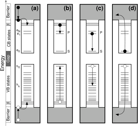
One distinguishes first between systems having a lone carrier, either electron or hole, and systems having both an electron and hole. A lone carrier can be produced by doping the dotbras_APL_2002 ; kammenerer_APL_2005 ; zibik_PhysicaE_2005 ; zibik_PRB_2004 ; zibik_PhysicaE_2005a ; sauvage_PRL_2002 or by electrochemical injection.guyot-sionnest_JCP_2005 Exciting a lone carrier and following its decay zibik_PRB_2004 ; zibik_PhysicaE_2005a ; sauvage_PRL_2002 is a specialized field and will be reviewed briefly in Sec. II.3. More commonly we encounter relaxation of systems having both photoexcited electrons and holes. This is reviewed next. Figure 1 sketches four non-radiative relaxation processes that take place following photocreation of an electron-hole pair in an (In,Ga)As/GaAs quantum dot system. The electron is shown as a solid dot and the hole as a circle. The processes are illustrated with a dot with sparse confined electron (CB) states , and with a much denser set of confined hole (VB) states as is characteristic of self-assembled dots. The continuum of states of the wetting layer (dashed region) and GaAs barrier (shaded) are also shown schematically. The main observed carrier relaxation processes are the following.
II.1 Barrier-to-wetting layer carrier capture
Non-resonant photoexcitation of an electron-hole pair in the barrier [Fig. 1(a)] often leads to capture by wetting-layer (WL) quasi-continua. This process consists of carrier thermalization within the GaAs barrier and subsequent capture by the WL. Barrier thermalization occurs within .siegert_PRB_2005 ; yuan_PhysicaB_1999 Siegert et al. measured time-resolved photoluminescence (PL) signal from the wetting layer of InAs/GaAs dots at high excitation and found a capture time of regardless of doping (Ref. siegert_PRB_2005, ). Similarly, in undoped dots, Sun et al. have found a capture time smaller that (Ref. sun_Nanotechnology_2005, ), while Yuan et al observed a capture time of about (Ref. yuan_PhysicaB_1999, ).
II.2 Carrier capture from the wetting layer into the dot
Following barrier-to-wetting layer carrier capture, the hole relaxes to the lowest-energy confined hole state while the electron is captured from the bottom of the wetting layer to the highest-energy confined state [illustrated by ; Fig. 1(b)]. Sosnowski et al.sosnowski_PRB_1998 found in time-resolved differential transmission experiments at low excitation in an (In,Ga)As/GaAs dot with two confined electron states that the electron capture time is . On the other hand, a combined capture time has been derived from time-resolved photoluminescence (PL) experiments at high excitation by several groups. (These times are affected by the subsequent intra-dot carrier relaxation.) Siegert et al.siegert_PRB_2005 have found a capture time of in undoped dots, and and in n-doped and p-doped dots, respectively.note_00 Similarly, Yuan et al. yuan_PhysicaB_1999 found a capture time within , while Sun et al. found a capture time of less than (Ref. sun_Nanotechnology_2005, ).
II.3 Relaxation of excited carriers within the dot
Following carrier capture from the wetting layer into the dot, carriers can experience different dynamical processes. These processes largely reflect the type of spacings that exist between various confined states. The (In,Ga)As/GaAs system has interesting properties in this respect. First, not only are these direct gap materials, but the competing band-structure valleys () are rather far energetically from [unlike InP or PbSe (Ref. landolt_bornstein_table, )], so these materials, specially InAs, are in fact strongly direct-gap systems. Second, the hole mass in InAs is much heavier than the electron mass, so confined hole states tend to be more densely spaced than electron states. Third, the electron states are arranged in “shells” and each shell shows intra-shell level splittings, e.g. are split by -, while inter-shell splittings are larger, e.g. - spacing is - (Refs. bras_APL_2002, ; kammenerer_APL_2005, ; zibik_PRB_2004, ; sauvage_PRL_2002, ; zibik_PhysicaE_2005, ; muller_APL_2003, ) (compared to in CdSe dots). Thus, the intra-shell splitting is of the order of (small wave vector) acoustic phonon energies, whereas inter-shell spacing is larger than (small wave vector) longitudinal optical phonon energies. Therefore, inter-shell relaxation via single-phonon emission due to electron-phonon coupling (within the Born-Oppenheimer adiabatic approximation) is expected to be ineffective—bockelmann_PRB_1990 ; benisty_PRB_1991 the phonon-bottleneck effect—because energy cannot be conserved in the inter-shell relaxation process. Finally, hole states do not form shells, with exception of flat dotsnarvaez_JAP_2005 (height of about Å), and the splitting between hole states is about -, thus comparable to acoustic phonon frequencies. Given these general characteristics, the main electron- and hole-relaxation channels within the dot are:
(a) Hole thermalization. The hole relaxes to , most likely via electron–acoustic-phonon emission. Such a hole relaxation has been found to occur within sub- times.sosnowski_PRB_1998 ; urayama_PRL_2001 Moreover, Quochi and co-workers showed that the hole relaxation time depends strongly on temperature: at and at (Ref. quochi_PhysicaB_2002, ). Note that in CdSe colloidal dots the existence of energy gaps of within the valence-band quasi-continuum was shown experimentallyxu_PRB_2002 and theoreticallycalifano_NanoL_2003 to slow down the hole thermalization.
(b) Intra-shell electron relaxation (e.g. ; Fig. 1). The electron relaxes from (- splitting), or between magnetic-field split states, via acoustic phonon emission. From optical pumb-probe measurements, Zibik et al. have recently deduced relaxation times of and for - splittings of and (Ref. zibik_PhysicaE_2005a, ), respectively. A model calculation that adopts longitudinal acoustic phonon emission predicts, correspondingly, values of and .zibik_PhysicaE_2005a
(c) Inter-shell electron relaxation for sole carrier and for electron-hole pair (e.g. ; Fig. 1) within the - separating the electronic shells. This relaxation is different if an electron-hole pair is present or just a sole electron (doped dot). As expected from the phonon bottleneck effect, inter-shell relaxation in (In,Ga)As/GaAs dots has been observed to be slow by Urayama and co-workersurayama_PRL_2001 (relaxation time of ) as well as Heitz and co-workersheitz_PRB_2001 (). In contrast, time-resolved optical measurements have clearly demonstrated that this inter-shell decay is a fast process whether a hole is present or not. For instance, in experiments in which both an electron and hole are present, Müller et al. have found decay times of at and - (depending upon excitation power) at room-temperature in interband-pump–intraband-probe experiments (Ref. muller_APL_2003, ); Boogart et al. found (low intensity) and (high intensity) within and , but (high intensity) at room-temperature, in time-resolved pump-probe differential reflectance spectroscopy (Ref. bogaart_icps27_2005, ); Sosnowski et al. found at in pump-probe differential transmission experiments (Ref. sosnowski_PRB_1998, ); De Giorgi et al. found at ( at high intensity) and at room-temperature in time-resolved PL upconversion experiments (Ref. de_giorgi_APL_2001, ); with the same experimental technique, applied to large (Å, Å) and small (Å, Å) dots, Boggess et al found, respectively, and below , and at and at (Ref. boggess_APL_2001, ); while Siegert et al. found that at the decay time corresponds to , , and for undoped, n-doped, and p-doped dots, respectively (Ref. siegert_PRB_2005, ). On the other hand, when a sole electron is present and no hole, the inter-shell relaxation time slows down by a factor of about 2-10. For instance, in -doped (In,Ga)As/GaAs quantum dots the low-temperature relaxation time has been extracted from pump-probe infra-red spectroscopy and is in the range of - in the experiments of Zibik et al. (Ref. zibik_PRB_2004, ) and - in the experiments of Sauvage et al. (Ref. sauvage_PRL_2002, ). In the latter, the room-temperature relaxation is for . Note that in earlier pump-probe interband absorption experiments at high excitation Sauvage et al. found a relaxation time of at room temperature (Ref. sauvage_APL_1998, ). The situation is similar in colloidal dots such as CdSe, where the inter-shell relaxation in the absence of a hole slows down to (Ref. guyot-sionnest_JCP_2005, ), relative to when an electron-hole pair is present.
Several relaxation mechanisms have been proposed as responsible for the fast inter-shell relaxation: multi-phonon emission,inoshita_PRB_1992 Auger (carrier-carrier) scattering,bockelmann_PRB_1992 ; jiang_PhysicaE_1998 ; ferreira_APL_1999 ; nielsen_PRB_2004 and polaron relaxationinoshita_PRB_1997 ; verzelen_PRB_2000 ; jacak_PRB_2002 ; seebeck_PRB_2005 . (We discuss the Auger and polaron models in Sec. III.)
II.4 Thermal escape of carriers from dot
Upon increasing temperature, the photoexcited electron and hole escape the confined states of the dot [Fig. 1(d)]. Thermal depopulation has been found to be significant at temperatures .de_giorgi_APL_2001 ; urayama_APL_2002 ; norris_JPD_2005 However, Heitz and co-workers have found the onset to be .heitz_PhysicaB_1999 In n-doped InAs/GaAs dots, Bras and co-workers showed that thermal depopulation becomes significant above (Ref. bras_APL_2002, ).
III Auger and polaron mechanisms for inter-shell decay
III.1 Auger relaxation via electron-hole scattering
Figure 1(c) illustrates this process whereby the hot electron decays by scattering a low-lying photoexcited hole into deep hole states like . Scattering takes place via the electron-hole Coulomb interaction, so this relaxation process does not take place in the absence of a photexcited hole. For the mechanism to be effective it requires energy conservation: The excess energy of the electron has to be elastically transfered to the hole [as sketched in Fig. 1, where ]. On the other hand, electronic level broadening due to phonons effectively relaxes this stringent condition.sosnowski_PRB_1998 In (In,Ga)As/GaAs self-assembled quantum dots the whereas in CdSe colloidal dots . In the latter case the decay via Auger process is highly effective.wang_PRL_2003 ; klimov_JPCB_2000 ; klimov_PRL_1998 ; guyot-sionnest_PRB_1999 In fact, Hendry et al. hendry_PRL_2006 have demonstrated the validity of the electron-hole Auger mechanism for relaxation in CdSe dots by measuring directly the hole thermalization time (Sec. II C) versus the electron excess energy. Moreover, in Ref. 48 Guyot-Sionnest and co-workers have shown that in CdSe dots the relaxation of electrons is slowed down upon inducing hole trapping at the surface of the dots. This is strong evidence in favor of relaxation due to electron-hole Auger scattering. The effectiveness of the Auger mechanism for relaxation in self-assembled dots has been previously addressed within model Hamiltonians only.jiang_PhysicaE_1998 ; ferreira_APL_1999 Here it will be calculated by using a fully atomistic approach. When the hole is absent (due to its capture by a hole-quencher, or when only an electron is injected into the dot) the Auger mechanism is not possible. In CdSe colloidal dots the alternative mechanism corresponds to the coupling of the electrons in the dot with virtual phonons of the environment.guyot-sionnest_JCP_2005 . In (In,Ga)As/GaAs self-assembled dots the polaron decay has been proposed instead.inoshita_PRB_1997 ; verzelen_PRB_2000 ; seebeck_PRB_2005
III.2 Polaron decay for a single excited electron (no hole)
This mechanism has been invoked to explain the electron relaxation to state in the absence of a hole. The confined electron states are assumed to be strongly coupled with the continuum of states arising from the phonon replicas of the localized states (e.g. , ), thereby, forming stable polaron states. In turn, these polaron states relax when the phonon component of the polaron relaxes due to phonon anharmonicity.verzelen_PRB_2000 Thus, assuming that the phonon component of the polaron originates from LO phonons, the phonon-bottleneck is circumvented by the emission of an LO and a TA phonon. This mechanism requires that the - energy difference be of the order of the zone-center optical phonon energy. In colloidal dots - for electrons while , so the polaron decay mechanism is not possible. On the other hand, for holes in colloidal dots -, which would make the polaron decay possible. In (In,Ga)As/GaAs self-assembled dots, for electrons and ranges from - for holes while , thus making the polaron decay feasible.
In the case of the inter-shell transition in (In,Ga)As/GaAs, the polaron state has been predicted to relax within a few picoseconds,verzelen_PRB_2000 leaving the excited electron in the state. This model explains the observed relaxation times in the absence of a hole (Sec. II.3).note-100 Further data that has been taken as evidence of the polaron model in (In,Ga)As/GaAs dots corresponds to the anticrossings in the energies of allowed magneto-photoluminescence transitions as the field is swept.hameau_PRL_1999 The magnitude of the anticrossings () present in the spectra is consistent with those predicted by the polaron model (Ref. hameau_PRL_1999, ). We note that in low-symmetry dots all states have the same -symmetry even without phonon displacements, and therefore they would anticross in the presence of a magnetic field. Whether the reason for lowering the symmetry to is phonon coupling or simply the correct atomistic dot symmetry of the non-vibrating dot remains to be determined.
IV Calculation of Auger cooling due to electron-hole scattering
We have calculated the Auger cooling lifetime of electrons in In0.6Ga0.4As/GaAs quantum dots within a pseudopotential-based atomistic approachzunger_pssb_2001 in order to establish if this mechanism leads to decay times within magnitude needed to explain low-excitation experiments in which a photoexcited hole is present.
IV.1 Method of calculation
We begin by calculating the single-particle ladder and of electron and hole states, respectively, of the (In,Ga)As/GaAs quantum dot. The wave function and energy of these states are solutions of the atomistic single-particle Schrödinger equation
| (1) |
Here, the actual potential of the solid (dot+GaAs barrier) is described by a superposition of (semiempirical) screened pseudopotentials for atom of type (In,Ga,As) with position within the dot or barrier, and a non-local pseudopotential that accounts for the spin-orbit interaction.williamson_PRB_2001 To solve Eq. (1), we expand in a linear combination of Bloch bands of material (InAs, GaAs), with wave vector k and band index , subjected to strain :wang_PRB_1999
| (2) |
This expansion has a main advantage over a plane-wave expansion: The Bloch bands can be intuitively chosen, which reduces the computational demand significantly.wang_PRB_1999 To calculate the electron Auger cooling lifetime due to electron-hole scattering at low temperatures, we proceed in two steps.
IV.1.1 Calculation of the Auger scattering rates for individulal electron-hole configurations
We consider as initial electron-hole configurations those corresponding to the electron in the -shell states and the hole in low-lying states ; and as the final scattering states those that correspond to an electron occupying the -shell state and a hole in a deep state [Fig. 1(c)], i.e . Then, we calculate the net, characteristic Auger scattering rate of the transition (), with a hole in state , by using Fermi’s golden rule:
| (3) |
Here, and correspond to the many-particle energy of the initial and final state, respectively, calculated at the single-configuration level of approximation.note_02 The electron-hole Coulomb scattering matrix elements are given by
| (4) |
where is the microscopic dielectric function derived by Resta.resta_PRB_1977 Note that in the actual computations, we introduce a phenomenological broadening of the final states that allow us to replace in Eq. (3) with a Gaussian function . One should understand as a phenomenological way to account for the phonon-induced (e.g. phonon broadening) finite lifetime of the excited single-particle hole states: . Considering that experimentally the relaxation of a hole in the wetting layer to takes about (Ref. sosnowski_PRB_1998, ), we estimate a lower bound for of . The phenomenological parameter has been used in previous calculations (Refs. jiang_PhysicaE_1998, and wang_PRL_2003, ).
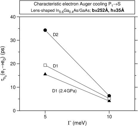
Figure 2 shows the characteristic Auger relaxation lifetime calculated for two values of in two lens-shaped In0.6Ga0.4As/GaAs quantum dots—D1 and D2—of size (Å, Å). These dots differ only in the random alloy disorder realization. For a phenomenological broadening , and . The strong difference shows that depends strongly upon the energy structure of the final states. For a more plausible value of the broadening, , for both dots.note-200 In addition, we find that ; D2 presents a difference of among these lifetimes. We also show, for a comparison, for dot D1 under a hydrostatic pressure of . Because this pressure does not change significantly the intraband energy structure of the confined states, but it primarily increases the localization of their wave functions,narvaez_PRB_2005a the characteristic relaxation lifetime is smaller than at ambient pressure.
IV.1.2 Solution of the rate equations describing the electron relaxation
Once we have calculated the characteristic times , we notice that (i) at low temperatures () there are two relevant initial electron-hole configurations and that decay to a single scattering configuration . (ii) In addition, due to the intra-shell relaxation, configuration decays to with a relaxation time between and .zibik_PRB_2004 Thus, we find the time-dependent occupation of , , and by solving numerically the following set of rate equations.
| (5) |
with initial conditions taken to be and . These initial conditions reflect the fact that the electrons captured in the dot have the same probability to decay to or (see Sec. II.3).
Here, and are the rates of transitions and , respectively, with
| (6) |
and
| (7) |
where . Finally, we extract electron Auger relaxation by fitting the time-dependence of the occupation probability to the expression . For the characteristic times and calculated with , and , the fit is excellent.
IV.2 Predicted and comparison with data
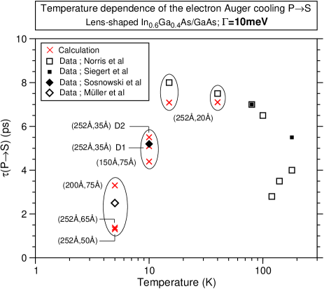
Figure 3 shows versus temperature for lens-shaped dots of different sizes [(base, height)]. In these calculations the broadening is larger than the average energy spacing of the relevant final states and . Two features are prominent. (i) decreases with both increasing height at a fixed base and increasing base at a fixed height. (ii) The Auger cooling lifetime of (Å,Å) is similar to that of dots with size (Å,Å) due to their similar single-configuration exciton gap (see below). Comparison with data: In Fig. 3 we also show data extracted from differential transmission spectroscopy experiments (Ref. norris_JPD_2005, ) and time-resolved photoluminescence experiments (Refs. [siegert_PRB_2005, ; muller_APL_2003, ; sosnowski_PRB_1998, ]) in (In,Ga)As/GaAs dots appear as squares and diamonds. A comparison with our calculated values shows the following. (i) We find excellent agreement between our calculated for the (Å,Å) dot D1 and the value of found by Sosnowski and co-workers in differential transmission spectroscopy in (In,Ga)As/GaAs dots with gap of (Ref. sosnowski_PRB_1998, ). Dot D2 and the dot with size (Å, Å) also compare well with experiment. (ii) The value of for at (Fig. 3) in InAs/GaAs dots with energy gap of that has been derived by Müller et al. (Ref. muller_APL_2003, ) from pump-probe intraband spectroscopy is in satisfactory agreement with our predicted values for (Å, Å), (Å, Å), and (Å, Å) dots. (iii) Our results for the flat dot (Å and Å) compare well with the data of Norris et al. (Ref. norris_JPD_2005, ) at low temperatures. The data of Siegert et al (Ref. siegert_PRB_2005, ) below is comparable to our low-temperature predicted values. Note that Norris et al. have found that above thermal escape of carriers [Fig. 1(e)] is important, which explains the large abrupt reduction of the Auger decay time seen in the data.norris_JPD_2005
IV.3 Trend of with exciton gap
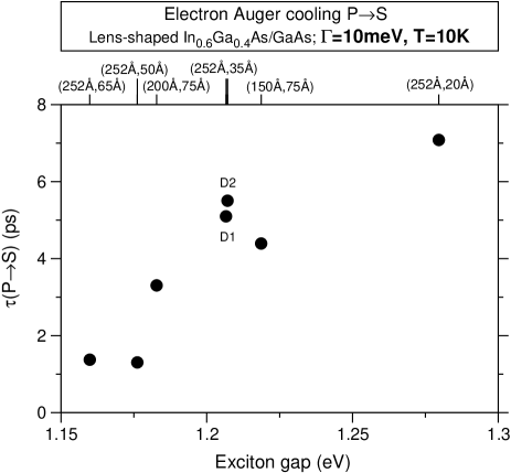
Figure 4(a) shows the calculated low-temperature () Auger relaxation lifetime as a function of the dot exciton gap for several In0.6Ga0.4As/GaAs quantum dots.note_01 Two important features emerge: (i) We find that ranges from - and decreases with the gap of the dots. As the - splittings of the lens-shaped dots is nearly the same, we attribute the reduction of to the increase of the joint density of states
| (8) |
that takes place as the gap of the dot decreases, due to the increase in the density of single-particle hole states.
IV.4 Comparison with other calculations for (In,Ga)As/GaAs dots
We have compared our results with two model calculations. (i) The 8-band calculation of Jiang and Singh (Ref. jiang_PhysicaE_1998, ) and (ii) the parabolic, single-band effective-mass calculation of Ferreira and Bastard (Ref. ferreira_APL_1999, ). Our results agree well with the calculation in (i). Namely, Jiang and Singh show an increase of the characteristic Auger cooling lifetime with decreasing . In addition, the results of Jiang and Sing compare satisfactorily (within a factor of two) with the value of observed by Sosnowsky et al.sosnowski_PRB_1998 A direct comparison with (ii) is not fully applicable since Ferreira and Bastard consider different initial states than those considered here (Sec. IV.1). In particular, the starting electron-hole pair states correspond, in our language, to and . However, it is interesting to see that Ferreira and Bastard find that the Auger-cooling lifetime is within and . Moreover, depending on the choice of initial e-h states, this lifetime either increases as gap decreases (in contrast to our predictions; Fig. 4) or viceversa.
IV.5 Digression: Comparison with calculations and data for CdSe colloidal dots
Wang et al.wang_PRL_2003 have calculated for CdSe colloidal dots using the same methodology as in this paper—pseudopotential-based atomistic approach—finding, respectively, relaxation times of and for a dots with radii of Å and Å. These results show that in contrast to In0.6Ga0.4As/GaAs dots, increases with decreasing the dot gap. Moreover, for In0.6Ga0.4As/GaAs dots, we predict s that are about a factor of 10 slower. The -based calculation of Efros and co-workersefros_SSC_1995 predicts Auger decay lifetimes in CdSe colloidal dots of almost independently of dot size for radii between Å and Å. While the magnitude of s that we find in InGaAs/GaAs is comparable to that of Efros and co-workers, the gap dependence is strikingly different. On the other hand, bleaching experiments in CdSe colloidal quantum dots show that the Auger cooling lifetime of electrons is below a picosecond and decreases as the exciton gap increases.klimov_JPCB_2000 [Note that the calculations of Wang and co-workerswnag_PRL_2003 capture reproduce these experimental findings.] We predict that in (In,Ga)As/GaAs self-assembled quantum dots and shows the opposite gap dependence [Fig. 4]. The gap dependence of in both colloidal and self-assembled dots is dictated by the gap (size) dependence of (i) the joint density of states [Eq. (8)] and (ii) the magnitude of the Coulomb scattering integrals [Eq. (4)]. While in (In,Ga)As/GaAs self-assembled dots the changes with size in the joint density of states prevails, in CdSe colloidal dots the changes of the Coulomb integrals dictates the gap dependence of .
V Summary
We have discussed several dynamical processes that photoexcited electrons and holes undergo in (In,Ga)As/GaAs self-assembled quantum dots, and calculated the inter-shell -to- electron decay lifetime in (In,Ga)As/GaAs self-assembled dot due to Auger electron-hole scattering. When only an electron (or only a hole) is present due to doping and this sole carrier is excited by a photon, its decay must involve a non-Auger mechanism (perhaps polaron decay). But when both an electron and hole are present we show that this Auger cooling takes place within picoseconds, which makes it an efficient inter-shell relaxation process compared to radiative recombination (). In addition, we predict that the lifetime increases with the exciton gap. Our pseudopotential-based calculations confirm earlier predictions of simplified, model calculations. The values we find for compare well with recent data in the presence of photoexcited holes. This finding complemented with our review of the data in the literature allows us to conclude that in the presence of a photoexcited hole there is no need to invoke the alternative polaron-decay mechanism for inter-shell electron relaxation. This conclusion could be tested in (In,Ga)As/GaAs dots by measuring the rate of hole thermalization versus the electron excess energy, or by measuring the electron relaxation rate after modifying the surface of the dot so as to cause hole trapping. Finally, a consistent picture of electron relaxation within quantum dots appears to demand two relaxation mechanisms: electron-hole Auger scattering and polaron decay.
Acknowledgements.
The authors thank Alberto Franceschetti (NREL) for useful discussions. This work was funded by U.S. DOE-SC-BES-DMS under Contract No. DE-AC36-99GO10337 to NREL.References
- (1) L. Ya. Karachinsky, S. Pellegrini, G. A. Buller, A. S. Sholnik, N. Yu. Gordeev, V. P. Evtikhiev, and V. B. Novikov, Appl. Phys. Lett. 84, 7 (2004).
- (2) P. D. Buckle, P. Dawson, S. A. Hall, X. Chen, M. J. Steer, D. J. Mowbray, M. S. Skolnick, and M. Hopkinson, J. Appl. Phys. 86, 2555 (1999).
- (3) C. Bardot, M. Schwab, M. Bayer, S. Fafard, Z. Wasilewski, and P. Hawrylak, Phys. Rev. B 72, 035314 (2005).
- (4) G. A. Narvaez, G. Bester, A. Zunger, Phys. Rev. B 72, 245318 (2005).
- (5) M. Califano, A. Franceschetti, and A. Zunger, Nano Lett. 5, 2360 (2005).
- (6) F. Bras, P. Boucaud, S. Sauvage, G. Fishman, and J.-M. Gérard, Appl. Phys. Lett. 80, 4620 (2002).
- (7) C. Kammerer, S. Sauvage, G. Fishman, and P. Boucaud, G. Patriarche, and A. Lematre, Appl. Phys. Lett. 87, 173113 (2005).
- (8) E. A. Zibik, A. D. Andreev, L. R. Wilson, M. J. Steer, R. P. Green, W. H. Ng, J. W. Cockburn, M. S. Skolnick, M. Hopkinson, Physica E 26, 105 (2005).
- (9) E. A. Zibik, L. R. Wilson, R. P. Green, G. Bastard, R. Ferreira, P. J. Phillips, D. A. Carder, J.-P. R. Wells, J. W. Cockburn, M. S. Skolnick, M. J. Steer, and M. Hopkinson, Phys. Rev. B 70, 161305(R) (2004).
- (10) E. A. Zibik, L. R. Wilson, R. P. Green, G. Bastard, R. Ferreira, P. J. Phillips, D. A. Carder, J-P. R. Wells, M. S. Skolnick, J. W. Cockburn, M. J. Steer, and M. Hopkinson, Physica E 26, 408 (2005).
- (11) S. Sauvage, P. Boucaud, R. P. S. M. Lobo, F. Bras, G. Fishman, R. Prazeres, F. Glotin, J. M. Ortega, J.-M. Gérard, Phys. Rev. Lett. 88, 177402 (2002).
- (12) P. Guyot-Sionnest, B. Wehrenberg, and D. Yu, J. Chem. Phys. 123, 074709 (2005).
- (13) J. Siegert, S. Marcinkeviius, and Q. X. Zhao, Phys. Rev. B 72, 085316 (2005).
- (14) Z. L. Yuan, E. R. A. D. Foo, J. F. Ryan, D. J. Mowbray, M. S. Skolnick, and M. Hopkinson, Physica B 272, 12 (1999).
- (15) K. W. Sun, J. W. Chen, B. C. Lee, C. P. Lee, and A. M. Kechiantz, Nanotechnology 16, 1530 (2005).
- (16) T. S. Sosnowski, T. B. Norris, H. Jiang, J. Singh, K. Kamath, and P. Bhattacharya, Phys. Rev. B 57, R9423 (1998).
- (17) The (In,Ga)As/GaAs dots of Ref. siegert_PRB_2005, show four PL transitions at high excitation that are attributed to four shells of electron states. Siegert et alsiegert_PRB_2005 measured the capture time by time-resolving the PL of the highest-energy transition; this time also includes the intra-continuum relaxation effects.
- (18) Landolt-Börnstein, Numerical Data and Functional Relationships in Science and Technology (Springer, Berlin, 1987), Vol. 22a.
- (19) T. Müller, F. F. Schrey, G. Strasser, and K. Unterrainer, Appl. Phys. Lett. 83, 3572 (2003).
- (20) U. Bockelmann and G. Bastard, Phys. Rev. B 42, 8947 (1990).
- (21) H. Benisty, C. M. Sotomayor-Torres, and C. Weisbuch, Phys. Rev. B 44, 10945 (1991).
- (22) G. A. Narvaez, G. Bester, and A. Zunger, J. Appl. Phys. 98, 043708 (2005).
- (23) J. Urayama, T. B. Norris, J. Singh, and P. Bhattacharya, Phys. Rev. Lett. 86, 4930 (2001).
- (24) F. Quochi, M. Dinu, N. H. Bonadeo, J. Shah, L. N. Pfeiffer, K. W. West, and P. M. Platzman, Physica B 314, 263 (2002).
- (25) S. Xu, A. A. Mikhailovsky, J. A. Hollingsworth, and V. I. Klimov, Phys. Rev. B 65, 045319 (2002).
- (26) M. Califano, G. Bester, and A. Zunger, Nano Lett. 3, 1197 (2003).
- (27) R. Heitz, H. Born, F. Guffarth, O. Stier, A. Schliwa, A. Hoffmann, and D. Bimberg, Phys. Rev. B 64, 241305(R) (2001).
- (28) E. W. Bogaart, J. E. M. Haverkort, T. Mano, R. Nötzel, and J. H. Wolter, AIP Conf. Proc. 772, 731 (2005).
- (29) M. De Giorgi, C. Lingk, G. von Plessen, J. Feldmann, S. De Rinaldis, A. Passaseo, M. De Vittorio, R. Cingolani, and M. Lomascolo, Appl. Phys. Lett. 79, 3968 (2001).
- (30) T. F. Boggess, L. Zhang, D. G. Deppe, D. L. Huffaker, and C. Cao, App. Phys. Lett. 78, 276 (2001).
- (31) S. Sauvage, P. Boucaud, F. Glotin, R. Prazeres, J. M. Ortega, A. Lematre, J.-M. Gérard, and V. Thierry-Flieg, Appl. Phys. Lett. 73, 3818 (1998).
- (32) T. Inoshita and H. Sakaki, Phys. Rev. B 46, 7260 (1992).
- (33) U. Bockelmann and T. Egeler, Phys. Rev. B 46, 15574 (1992).
- (34) H. Jiang and J. Singh, Physica E 2, 720 (1998).
- (35) R. Ferreira and G. Bastard, Appl. Phys. Lett. 74, 2818 (1999).
- (36) T. R. Nielsen, P. Gartner, and F. Jahnke, Phys. Rev. B 69, 235314 (2004).
- (37) O. Verzelen, R. Ferreira, G. Bastard, Phys. Rev. B 62, R4809 (2000).
- (38) L. Jacak, J. Krasnyj, D. Jacak, P. Machnikowski, Phys. Rev. B 65, 113305 (2002).
- (39) T. Inoshita and H. Sakaki, Phys. Rev. B 56, R4355 (1997).
- (40) J. Seebeck, T. R. Nielsen, P. Gartner, and F. Jahnke, Phys. Rev. B 71, 125327 (2005).
- (41) T. B. Norris, K. Kim, J. Urayama, Z. K. Wu, J. Singh, and P. K. Batthacharya, J. Phys. D: Appl. Phys. 38, 2077 (2005).
- (42) J. Urayama, T. B. Norris, H. Jiang, J. Singh, and P. Bhattacharya, Appl. Phys. Lett. 80, 2162 (2002).
- (43) R. Heitz, I. Mukhametzanov, H. Born, M. Grundmann, A. Hoffman, A. Madhukar, and D. Bimberg, Physica B 272, 8 (1999).
- (44) L.-W. Wang, M. Califano, A. Zunger, and A. Franceschetti, Phys. Rev. Lett. 91, 056404 (2003).
- (45) V. I. Klimov, J. Phys. Chem. B 104, 6112 (2000).
- (46) V. I. Klimov and D. W. McBranch, Phys. Rev. Lett. 80, 4028 (1998).
- (47) P. Guyot-Sionnest, M. Shim, C. Matranga, and M. Hines, Phys. Rev. B 60, R2181 (1999).
- (48) E. Hendry, M. Koeberg, F. Wang, H. Zhang, C. de Mello Donegá, D. Vanmeakelbergh, and M. Bonn, Phys. Rev. Lett. 96, 057408 (2006).
- (49) Note that by using electron-hole coupling strength in the quantum dot as an adjustable parameter, the polaronic decay model has been used to fit the data for the inter-shell transition in the experiments of Ref. zibik_PRB_2004, .
- (50) S. Hameau, Y. Guldner, O. Verzelen, R. Ferreira, G. Bastard, J. Zeman, A. Lematre, and J. M. Gérard, Phys. Rev. Lett. 83, 4152 (1999).
- (51) A. Zunger, phys. stat. sol. (b) 224 , 727 (2001).
- (52) A. J. Williamson, L.-W. Wang, and A. Zunger, Phys. Rev. B 62, 12963 (2000).
- (53) L.-W. Wang and A. Zunger, Phys. Rev. B 59, 15806 (1999).
- (54) We disregard both the electron-hole exchange interaction, which has a magnitude of a few , and correlations that would arise from electron-hole configuration mixing.
- (55) R. Resta, Phys. Rev. B 16, 2717 (1977).
- (56) Note that unless the microscopic character of the random alloy disorder changes significantly the small lifetime of the holes, the choice of is independent of disorder. We have made this assumption, as assessing the microscopic effects of alloy disorder on the characteristic Auger relaxation times lays beyond the scope of the present paper.
- (57) G. A. Narvaez, G. Bester, and A. Zunger, Phys. Rev. B 72, 041307(R) (2005).
- (58) The dot exciton gap is calculated within the single-configuration approximation, which predicts a gap that is an excellent approximation to the actual fully-correlated exciton gap.
- (59) Al. L. Efros, V. A. Kharchenko, and M. Rosen, Solid State Comm. 93, 281 (1995).