eurm10 \checkfontmsam10
Part I *
1–4
Molecular Dynamics Simulation of Collisions between Hydrogen and Graphite
Abstract
Hydrogen adsorption by graphite is examined by classical molecular dynamics simulation using a modified Brenner REBO potential. Such interactions are typical in chemical sputtering experiments, and knowledge of the fundamental behavior of hydrogen and graphene in collisional conditions is essential for modeling the sputtering mechanism. The hydrogen adsorption rate is found to be dependent on the incident hydrogen energy and not on graphene temperature. Rather than destroying the graphene, hydrogen incidence at energies of less than 100 eV can be classified into three regimes of adsorption, reflection and penetration through one or more graphene layers. Incidence at the lowest energies is shown to distort the graphene structure.
1 Introduction
In chemical sputtering experiments, such as experiments using the diver tor of a nuclear fusion device, plasma–carbon interactions have been reported to yield hydrocarbon molecules of small number of atoms[[1]]. However, the mechanism of hydrocarbon generation has not been elucidated yet. In the present study, this mechanism is examined in detail through simulation of the collision of hydrogen atoms with graphene as one of the fundamental processes in plasma–carbon interaction.
A classical molecular dynamics (CMD) simulation scheme is adopted in the present study to allow the dynamics of a many-particle system to be simulated over an adequate length of time given limited computer resources. Quantum mechanical simulations could not be performed for the same time of interaction using the resources available. A new model potential between hydrogen and graphene is introduced for these simulations in order to incorporate Brenner’s REBO potential [[2]] as the basis for the chemical reaction. The carbon wall is treated as graphene layers which are minimal structure of both a graphite and a carbon fiber. However, for simplification, they do not inter-layer interaction. The kinetic energy of incident hydrogen is set to less than 100 eV to facilitate comparison with the results of divertor experiments.
2 Simulation model
The interaction potential in CMD has been developed through contributions by many theorists [[2]-[5]]. The Brenner’s original REBO potential [[2]] has the following form:
| (1) |
where is the distance between atoms and , is an attractive term, is a repulsive term, and the function includes all the effects of molecular orbitals. However, if chemical reactions occur, the REBO potential breaks energy conservation. To deal with chemical reactions, new functions expressing conjugation effects are thus proposed:
| (2) |
where is a cut-off function for the distance between atoms, and
| (6) | |||
| (7) |
In contrast to Brenner’s original formulation [[2]], the second and third terms of are not squared. The tricubic spline functions and in Ref. [2] are redefined, as the original functions have as a variable. Denoting a new function of by , we obtain , and for the other cases. The spline in Ref. [2] is redefined in a similar way. The above modifications of , and provide differentiability at the cut-off point, conserving the total energy in the chemical reaction. This modified potential is employed in the present CMD simulations.
Graphenes are set parallel to the plane in region. Each graphene is comprised of 160 carbon atoms with a periodic boundary condition. The velocities of all atoms in the graphene are distributed according to a Maxwell’s distribution at the graphene temperature. Incident hydrogen atoms arrive normal to the graphenes from the Å. The simulation continues until the incident atom is reflected, the atom leaves the graphenes into the region, or until the atom becomes trapped by the graphenes.
A total of 200 simulations was performed for each graphene temperature and incident energy, with the initial position of the hydrogen atom on the Å plane varied randomly to obtain statistical information. The present CMD simulation satisfies the constant-volume-energy (NVE) condition.

|

|
|
|
3 Results and Discussion
In the present simulations of incident hydrogen energies of less than 100 eV, the hydrogen atoms were found to be absorbed (or reflected) by the graphenes without destroying the graphenes. As shown in Fig. 1(a), the simulations suggest that the hydrogen adsorption rate on graphene is independent of the graphene temperature. This result is not consistent with experimental facts[[6, 7]]. However, the temperature defined in this simulation () is not the same as the temperature measured in experiments () due to the omission of inter-layer interaction in the present simulation. The graphenes form a domain structure by the inter-layer interaction in the carbon wall. The experimental temperature therefore includes all the kinetic energy of the relative motion of each domain, each layer, and each atom, whereas accounts solely for the kinetic energy of atoms.
Figure 1(b) shows that the hydrogen adsorption rate is dependent on . The mechanism of adsorption can be classified into the following three types of processes:
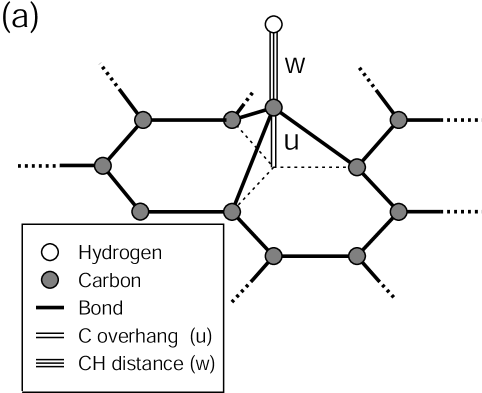
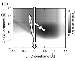
Adsorption at eV: As the incident hydrogen atom approaches the graphene, the nearest carbon atom overhangs spontaneously from the flat graphene (Fig. 2(a)). Because, this deformation of the graphene leads the total potential energy to the minimum point (arrow 1, Fig. 2(b)). The kinetic energy converted from potential energy is diffused into the entire atoms in the graphene through the overhanging carbon atom. The incident atom thus loses kinetic energy and is trapped.
Reflection at eV eV: The velocity of the incident atom is so high under high-energy conditions that spontaneous overhanging of the carbon atom can not occur, and the total potential does not pass through the minimum point. The incident atom bounces off this potential barrier (arrow 2, Fig. 2(b)) and the incident atom is reflected. The adsorption rate under such conditions is therefore low.
Penetration at eV: When the energy is greater than the potential barrier, the incident atom penetrates the graphene (arrow 3, Fig. 2(b)). The incident atom gradually loses kinetic energy by repulsion of the carbon atom as it penetrating several graphene layers. The reaction thus eventually changes into a reflection process. After repeated bouncing between graphene layers, the incidence atom is trapped.
4 Conclusions
The collision processes between incident hydrogen and graphene at energies of less than 100 eV were investigated by CMD simulations using a modified REBO potential. It was found that hydrogen does not destroy the graphene at these energies, but is instead absorbed or reflected by the graphene. The rate of hydrogen adsorption was shown to be dependent on the incident energy and not on the graphene temperature. The collision behavior was classified into the three processes; absorption of hydrogen in graphene ( eV), reflection by graphene ( eV eV), and penetration through one or more graphenes ( eV).
19
References
- [1] Nakano, T., Kudo, H., Higashijima, S., Asakura, N., Takenaga, H., Sugie, T. and Itami, K. 2002 Nucl. Fusion 42, 689.
- [2] Brenner, D. W., Shenderova, O. A., Harrison, J. A., Stuart, S. J., Ni, B. and Sinnott, S. B. 2002 J. Phys. Condens. Matter 14, 783.
- [3] Morse, P. M. 1929 Phys. Rev. 34, 57.
- [4] Abell, G. C. 1985 Phys. Rev. B 31, 6184.
- [5] Tersoff, J. 1987 Phys. Rev. B 37, 6991.
- [6] Mech, B. V., Haasz, A. A. and Davis, J. W. 1997 J. Nucl. Mater. 241–243, 1147.
- [7] Roth, J., and Garcia-Rosales, C. 1996 Nucl. Fusion 36, 1647.