Dual-frequency ferromagnetic resonance
Abstract
We describe a new experimental technique to investigate coupling effects between different layers or modes in ferromagnetic resonance (FMR). Dual FMR frequencies are excited (2-8 GHz) simultaneously and detected selectively in a broadband RF circuit, using lock-in amplifier detection at separate modulation frequencies.
I Introduction
Ferromagnetic resonance (FMR) precession of ferromagnetic alloys and heterostructures is technologically important since it determines the GHz dynamics of spin electronic devices. Recently, novel long-ranged dynamic coupling mechanisms between layers in heterostructures, through the transient excitation of spin currents, have been observed experimentallyTserkovnyak-rmp . Some of these processes could be elucidated if motions of individual layers can be excited independently, allowing the effects of higher amplitude motion at one layer to be characterized in the resonance at an opposite layer.
Experiments on driven FMR modes in ferromagnetic multilayers so far have typically focused on the situation with single drive excitation. Dual-drive excitations cannot be found in the literature except in a few studies of nonlinear interactions between magnetostatic waves in yttrium-iron-garnet filmsmar-jap1 ; mar-jap2 . We have developed a dual-frequency FMR technique to study interactions between FMR modes. Through the adjustment of pumping power at mode 1 (excited at ), we can examine effects on FMR line intensity, width, or shape at mode 2 (excited at ).
In this article, we describe the apparatus for dual-frequency FMR measurements. FMR is excited at two frequencies using dual RF sources, combined at a power divider, and delivered to the ferromagnetic sample using a broadband coplanar waveguide (CPW). The response of individual FMR modes is detected by modulating each RF source at a separate low modulation frequency and locking in to these two frequencies with separate lock-in amplifiers. The technique is validated with a Ni81Fe19 thin film sample, where dual-frequency FMR is proved to be selective of resonance frequency. With this technique, investigations have been made in a Ni81Fe19/Cu/Co93Zr7 multilayer, where some influence of pumped Ni81Fe19 precession on the Co93Zr7 resonance may be seen.
II Apparatus
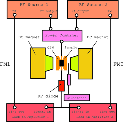
The block diagram of the experimental setup of dual-frequency FMR is shown in Fig. 1, where broadband (2-8 GHz) swept-field ferromagnetic resonance (FMR) is measured. Lock-in amplifier detection through frequency modulation is used in our FMR measurements. Apart from the dual frequency capability, our measurements are similar to conventional FMR cavity measurementsheinrich , although network analyzers are often used instead of lock-in amplifier for phase-sensitive detection in conventional broadband FMR spectrometersDenysenkov-rsi .
The microwave sources consist of two independently controllable frequency sweepers: RF source 1 and RF source 2. RF source 1 is a home-built, fixed-frequency source at 2.3 GHz (), variable in output from -50 to 22 dBm. We used a filtered amplified higher harmonic of a 88 MHz signal from a Waveteck 3000 signal with FM capability. RF source 2 is a Wiltron 6668B sweep generator operated in cw mode, with tunable frequency () in the range of 0-40 GHz, variable output from -50 to 15 dBm, and FM capability. The dual microwave generators are used to generate dual rf signals (, ) simultaneously. The two independent rf sources modulated at separate frequencies (, ) are combined with a Anaren 42020 broadband power combiner/divider (2-8 GHz), which attenuates each input by 3 dB in transmission, and then delivered to the ferromagnetic thin film sample through a lithographic coplanar waveguide (CPW) with a 100 m center conductor width. The RF field delivery configuration here is similar to that used in PIMM (pulsed inductive microwave magnetometer) measurementskos-rsi , substituting cw microwave sources for the pulse generator.
The thin film sample is placed film-side down onto the top of the CPW, with a thin layer of photoresist spin-coated onto the film to prevent it from shorting the CPW. The CPW, used to pump the thin film sample with combined microwave (2-8 GHz) excitations from two synthesized microwave generators, is constructed by standard lithographic techniques and placed inside a Fe core electromagnet. The electromagnet has a gap of 2 cm and a maximum field of 1.0 Tesla at 40 Ampere, controlled by parallel KEPCO-BOP-20/20M current sources. The Fe core electromagnet provides applied magnetic bias field along the center conductor of CPW, which is measured directly using a transverse hall probe monitored by a Lakeshore 421 Gaussmeter.
Transmitted rf signals through the magnetic thin film sample are detected at a microwave diode (0-18 GHz), the output of which is sent to the inputs of two lock-in amplifiers (lock-in 1 of SR810, and lock-in 2 of SR830). The outputs of the lock-in amplifiers provide the modulation to the transmitted rf signals at separate modulation frequencies: ( 120 Hz) for , and ( 540 Hz) for . A microcomputer equipped with a GPIB bus communicates with the SR810/830 and the Wiltron 6668B; analog inputs (10 V) at the SR830 read the corrected output of the Lakeshore 421 Gaussmeter, and parallel analog outputs (5 V) control the Kepco power supplies. All these features allow the system to be fully automated.
In operation, the dual-frequency FMR measurement can sweep frequencies at and fields , while monitoring the diode signals at () and (). Power levels at are set manually through a variable attenuator. A high-precision (Keithley 2000) DMM, also under GPIB control, was available to monitor the DC diode signals in the same measurements.
III Experiment
A single layer sample of Ni81Fe19(25 nm) and a trilayer structure of Ni81Fe19(25 nm)/Cu(20 nm)/Co93Zr7(25 nm), were grown by UHV magnetron sputtering from alloy targets at a base pressure of 410-9 torr onto Si/SiO2 substrates. A 20 Oe deposition field was applied to induce unidirectional anisotropy in the film plane. More details on deposition conditions can be found in our previous workguan-jap .
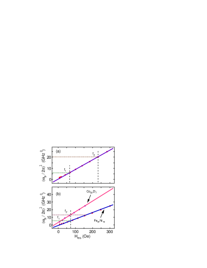
Conventional broadband FMR measurements (RF source 1 is off, and RF source 2 is on) were made on both Ni81Fe19 and Ni81Fe19/Cu/Co93Zr7 thin film samples at several selected frequencies (from 0 to 5 GHz) to determine the Kittel relationskittel between microwave frequency () and resonance field (). For in-plane magnetization in a thin film, the Kittel relation can be expressed askittel :
| (1) |
where is an effective field due to anisotropy.
The Ni81Fe19 thin film sample was then measured using dual-frequency FMR, where two different FMR modes were excited independently, using separate resonance frequencies ( = 2.3 GHz, = 4.5 GHz) at fixed field. In the Ni81Fe19/Cu/Co93Zr7 trilayer sample, both the Ni81Fe19 layer and the Co93Zr7 layer were excited near resonance simultaneously, choosing for = 2.3 GHz, through the adjustment of (to 3.8 GHz). The effects of variable power at on the Co93Zr7 resonance at were investigated.
IV Results and discussion
The results of conventional broadband FMR measurements on both Ni81Fe19 and Ni81Fe19/Cu/Co93Zr7 thin film samples are presented in Fig. 2. We show as a function of . and denote the selected frequencies of excited FMR modes in dual-frequency FMR measurements on the same samples (shown in Fig. 3 and Fig. 4). Solid lines are linear fits based on Eq. (1). Two branches were observed for the Ni81Fe19/Cu/Co93Zr7 thin film sample, corresponding mostly to the separate resonances of the Ni81Fe19 layer and the Co93Zr7 layer, with some weak ferromagnetic coupling ( 5 Oe).
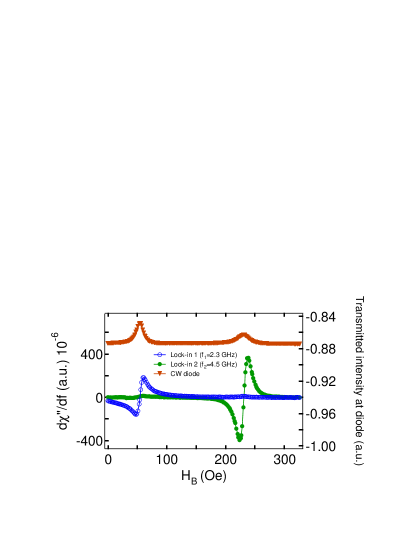
Validation of frequency selectivity in dual-frequency FMR is shown in Fig. 3. Two different FMR modes were excited in the Ni81Fe19 thin film sample at two selective resonance frequencies ( = 2.3 GHz, = 4.5 GHz) and then detected selectively using dual lock-in amplifiers (lock-in 1, lock-in 2), respectively. Two absorption peaks were observed for the total transmitted signal, where the positions and widths of the two absorption peaks correspond closely with those found selectively at and .
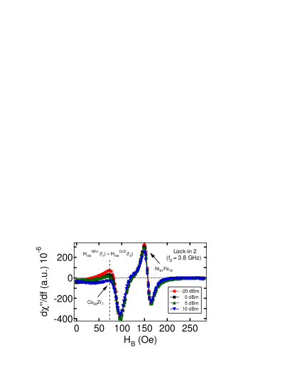
Dual-frequency FMR measurement on the Ni81Fe19/Cu/Co93Zr7 trilayer thin film sample is presented in Fig. 4, where the effects of pumped Ni81Fe19 precession at = 2.3 GHz were investigated on the Co93Zr7 resonance at = 3.8 GHz. This frequency (f1) sets the Ni81Fe19 layer into FMR at = 72.5 Oe. With rf power of RF source 2 fixed at a low value (-5 dBm), we varied the pumping power of RF source 1, from -20 dBm to +10 dBm, measured at the diode. As shown in Fig. 4, two separate FMR modes were observed for each value of the pumping power of RF source 1, where the mode at the low-field side corresponded primarily to the resonance of the Co93Zr7 layer. Some variations can be seen in both the line intensity and the symmetry of the Co93Zr7 FMR modes as a function of power pumped into the Ni81Fe19 resonance. It is also evident that the high power excited at has no discernible influence on the Ni81Fe19 resonance measured at , as expected. However, a quantitative estimate of any dynamic coupling between Ni81Fe19 and Co93Zr7 layers could not be made, as the residual influence of the static ( 5 Oe) coupling could not be excluded. It is additionally important to drive the Ni81Fe19 resonance symmetrically over the low-field region, which requires a second variable frequency source at .
By using dual-frequency FMR technique, we can selectively excite several different FMR modes in a ferromagnetic alloy and heterostructures, and the nature of coupling interactions between multiple FMR modes could thus be probed.We remark that the technique presented could be extended to fixed-field, swept-frequency measurement, or to track the Kittel resonance at as field is swept. With much higher power amplification and some cooling capability, nonlinear interactions between magnetostatic spin-wave modes (MSSW) could be studied as well. Finally, the frequency range can be extended to 20 GHz, or even to 40 GHz, through the use of different power dividers.
V Conclusion
A new experimental technique, dual-frequency ferromagnetic resonance (FMR), has been developed to investigate coupling effects between different FMR modes. This new technique is able to excite different FMR modes simultaneously and independently, while separating the properties of each.
VI Acknowledgements
This work was partially supported by the Army Research Office with Grant No. ARO-43986-MS-YIP, and the National Science Foundation with Grant No. NSF-DMR-02-39724. This work has used the shared experimental facilities that are supported primarily by the MRSEC(Columbia) program of the National Science Foundation under Contract No. NSF-DMR-0213574.
References
- (1) Y. Tserkovnyak, A. Brataas, G. E. W. Bauer, and B. I. Halperin, Rev. Mod. Phys. 77, 1375 (2005).
- (2) D. J. Mar, T. L. Carroll, L. M. Pecora, J. F. Heagy, and F. J. Rachford, J. Appl. Phys. 80, 1878 (1996).
- (3) D. J. Mar, T. L. Carroll, L. M. Pecora, and F. J. Rachford, J. Appl. Phys. 81, 5734 (1997).
- (4) B. Heinrich, Ultrathin Magnetic Structures II, edited by B. Heinrich and J. A. C. Bland (Springer-Verlag, Berlin, 1994).
- (5) V. P. Denysenkov and A. M. Grishin, Rev. Sci. Instrum. 74, 3400 (2003).
- (6) A. Kos, T. Silva, and P. Kabos, Rev. Sci. Instrum. 73, 3563 (2002).
- (7) Y. Guan, Z. Dios, D. A. Arena, L. Cheng, and W. E. Bailey, J. Appl. Phys. 97, 10A719 (2005).
- (8) Charles Kittel, Introduction to Solid State Physics (Wiley, 2005)