Low-temperature scanning probe microscopy using a tuning fork transducer
Abstract
We have developed a low-temperature scanning probe microscope using a quartz tuning fork operating at 4.2 K. A silicon tip from a commercial cantilever was attached to one prong of the tuning fork. With a metallic coating, a potential could be applied to the tip to sense the charge distribution in a sample, while with a magnetically coated tip, magnetic force imaging could be performed. For the coarse approach mechanism, we developed a reliable low-temperature walker with low material cost and simple machining. We have obtained Coulomb force images of boron nanowires at room temperature and magnetic nano-structures at low temperature. For lift-mode scanning, we employed a frequency detection mode for the first topographic scan and phase detection mode for the second lift scan.
pacs:
07.79.Pk, 68.37.Rt, 68.37.Ps, 07.79.-v, 87.64.DzI Introduction
With current technology, devices can routinely be fabricated with dimensions less than 100 nm. To measure the physical properties of these devices such as local electric field, magnetic field and local charge density, scanning probe microscopy (SPM) has proved extremely versatile. Using this technique, one can even manipulate or reconstruct atomic scale devices in order to modify their physical properties. Among the many different types of SPMs, the scanning tunnelling microscope (STM) has been used for probing samples with the highest spatial resolution. One limitation of the STM is that the sample (including the substrate) must be electrically conducting. In measurements on real devices, this limitation can be a crucial disadvantage, because almost all kinds of real devices are fabricated on an insulating (or semiconducting) substrate. A scanning force microscope (SFM) combined with a STM is a good solution for nano-scale measurement of real devices. A preliminary topographic scan with atomic force microscopy (AFM) on an insulating substrate gives information on the conducting regions of the device. A subsequent scan with a STM or an electrostatic force microscope (EFM) can then be taken on the conducting portions of the device.
To realize a SFM-STM combination using a conventional cantilever-based SFM, a metallic tip needs to be mounted on the SFM cantilever. However, the SFM cantilever should be stiff enough to control accurate motion of the STM tip. In general, conventional micro-machined cantilevers have low stiffness ( 1 N/m). By attaching a STM tip on a quartz crystal tuning fork, a SFM combined with STM can be realizedGiessibl ; Giessibl1 since the tuning fork is stiff enough to control the motion of the tip but sensitive enough to measure atomic forces.Giessibl2
There have been many attempts to develop low temperature SFMs using, for example, fiber optic interferometryMoser ; Allers or piezoresistive cantilever detection Yuan ; Volodin . However, these methods use micro-machined cantilevers and it is hard to modify the cantilevers to serve in a SFM-STM combined system.
Using a tuning fork as a force sensor for SFM overcomes many of the drawbacks of other designs: (i) Because the tuning fork sensor is stiff, the tip mounted on the tuning fork can be controlled accurately; (ii) the minimum controllable dithering amplitude is much smaller than that of a cantilever, which allows high resolution imaging;Giessibl2 (iii) no optics are required and it is simple and compact; and (iv) because the dissipated power can be reduced down to 1 pW,Giessibl2 the SFM can be operated at millikelvin temperatures.Rychen ; Patil ; Kramer ; Brown
We report here the details of the development of a low temperature SFM using a tuning fork. The increased resolution and sensitivity are due to the use of miniaturized tuning forks with low stiffness and operation at low temperatures, which increases the of the tuning fork. Our technique of attaching commercial cantilever tips to the tuning fork minimizes the loading of the tuning fork, which improves its sensitivity.
II Experimental Details
II.1 Coarse Approach Mechanism
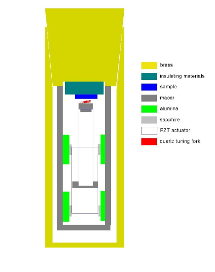
The scanning head of the SFM was mounted on the end of an insert that could be cooled to 77 K and 4.2 K by dipping into liquid nitrogen and liquid helium respectively. Figure 1 shows the inside structure of the insert with a brass housing. The tuning fork sensor (red) was mounted on a Macor (machinable ceramic) plate (gray) having a low thermal expansion coefficient. A tube scanner holding the Macor plate provided the scanning motion of the head. The scanner and head were mounted on a piezoelectric walker which served as the coarse approach mechanism. The supporting structure for the walker was also made of Macor to match the thermal expansion of the walker. A magnetic field could also be applied using a superconducting magnet located outside the insert.
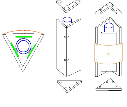
For the coarse approach mechanism, we modified the walker design of Gupta and Ng Gupta (GN) by replacing some materials in their original design for operation at low temperatures, as shown in Fig. 2. The housing material (stainless steel in the original design) was replaced by Macor. In GN’s design, the V-groove shaped housing was machined from a single piece of metal, while in the design of S.H Pan,Pan the housing was machined from a single piece of Macor. It is very time consuming to make a V-groove on a Macor piece because Macor is brittle and must be machined slowly. In our design, five pieces of Macor plate of 3 mm thickness were put together with screws, as shown in Fig. 2. The middle Macor plate was held by a BeCu plate spring (orange) and sapphire ball (red). Using this design, one can save material and machining costs. Following the design of GN’s walker, the piezo actuator was made from a single PZT tube (blue) of 5 cm length and 1 cm diameter. The tube was divided into six independent actuators with six slits.Gupta The inside electrode served as the ground and each of the six electrodes was connected to a high voltage driving signal. GN suggest the wires connecting the actuators should be coiled to reduce mechanical tension.Gupta However, we found that the wires need not be coiled if the wires are thin ( 0.1 mm) and long enough. We used both normal copper and superconducting wires with enamel coating.
Polished alumina plates 1 mm thick (green in Fig. 2) were attached to the housing surface with epoxy glue to minimize the friction between the sapphire disks (gray) attached to the PZT tube (blue) and the walker housing. At first, we tried a brass coarse approach housing without the alumina plates, that is, the sapphire disks attached to the PZT tube slid on a polished metallic surface, following GN’s design. In this case, the coarse approach mechanism seemed to work well initially, but always froze after several runs. Careful inspection showed that the metallic surface of the housing was scratched by the sapphire disk edge. In the case of the sapphire/alumina combination, this did not occur. With other choices of the contact materials (e.g., sapphire/glass), the walker froze at liquid nitrogen temperatures, after it had been used several times. We found that the proper motion of the walker did not depend strongly on the force exerted by BeCu spring against the middle plate, which was on the order of 1 N.
To drive the walker, control electronics were built that generated a sequence of pulses of up to 150 V peak for each of six channels following the design of GN.Gupta Three of the output voltage channels of the electronics were connected to the upper sections of the tube actuator and the other three were connected to the lower sections. A single step of the walker consisted of a series of six pulses generated in sequence. To move the walker up, for example, the three voltage channels connected to the upper actuators were pulsed with a positive voltage, while the three channels connected to the lower actuators were pulsed with a negative voltage. For movement in the opposite direction, the voltage polarities were reversed. The pulses were synchronized with the line frequency of 60 Hz. The time interval between the pulses was varied from 100 s and 1 ms: this did not cause a noticeable change in the speed of the walker.
At liquid nitrogen temperature, the driving pulse occasionally caused a discharge between the electrodes of the PZT actuator when the chamber had a few hundred millitorr of exchange gas (helium or air). When the discharge problem occurred, the sound of the walker motion became loud and the high voltage amplifiers driving the walker were burned out. A more serious problem was that the metal film of the electrodes on the PZT actuator was sputtered, coating the alumina sliding plates. Once the alumina plates were coated with metal, the walker froze. The contaminated alumina plate needed to be polished to be used again. To avoid the discharge problem, the amount of the exchange gas was kept less than few hundred millitorr and the driving voltage was kept less than 100 V.
II.2 Tuning fork transducer and control circuitry
The resonance frequency shift and phase shift were measured by commercial phase-locked-loop electronics (easyPLL from Nanosurf).Easypll An ac voltage on or near the resonance frequency of the tuning fork was applied to one electrode of the tuning fork and the resulting ac current measured using a room-temperature home-made current-voltage amplifier. The tuning fork signal was passed through a coaxial cable 1 m long and was fed into the current-voltage amplifier located outside the insert. The current-voltage amplifier consisted of a LF356 operational amplifier with a 5 M load resistor followed by 100 gain instrumentation amplifier (Analog Device’s AD524). The typical dithering amplitude was 5 nm at a drive voltage of 5 mV.
Each prong of the tuning fork was 2.2 mm long, 190 m thick and 100 m wide. Its spring constant was estimated to be 1300 N/m. For the tip, the tip from a commercial AFM cantilever (Mikromasch) mounted on a Si chip was used. (A commercial MFM cantilever was used for MFM measurements.) To attach the tip to the tuning fork, a home-made 3-axis micromanipulator that consisted of three translational stages with 5 m resolution and a long working distance (50 mm) optical microscope was constructed. In order to mount the tip on the tuning fork, the cantilever tip was first aligned precisely to the desired position on the tuning fork prong. The cantilever tip was then retracted and a small drop of epoxy ( 30 m diameter) was placed on the contact point on the prong using a 50 m wire. With this technique, a very small amount of epoxy could be applied to attach the tip. Finally, the tip was moved onto the epoxy and the system let stand for more than an hour to let the epoxy cure. After curing, the Si chip was retracted, breaking the cantilever and leaving the tip on the tuning-fork prong. The total size of the remaining tip was approximately 20 m 20 m, with a height of 15-20 m.
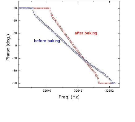
After the tip was mounted on one prong of the tuning fork with epoxy glue, the resonance full width at half maximum (FWHM) of the amplitude spectrum was about 5 Hz in air (1 Hz in vacuum) and the resonance frequency shift was a few tens of Hz. After application of the epoxy, the phase shift spectra of the tuning fork were measured before and after the tuning fork was baked (Fig. 3). It can be seen that the -value of the tuning fork was increased after it was baked at 200 ∘C. We attribute this tendency to an increase in the stiffness of the epoxy. The final -value was about 104 in air ( in vacuum). These -values were almost the same as those before the tip was mounted. The remarkably small change in the -values resulted from the very small amount of glue used. The large -value of the tuning fork (roughly 100 times larger than that of a conventional cantilever) compensated partly for the high stiffness of the tuning fork in terms of the overall sensitivity of the instrument.Seo1
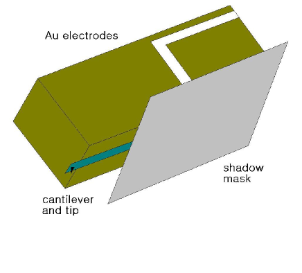
For EFM measurements, one needs a metallic tip electrically connected to an electrode. To accomplish this, the end of a prong of the tuning fork including the tip was coated with metal using an e-beam evaporator. As shown in Fig. 4, a metal shadow mask was used to selectively evaporate the metal film on the tip and prong. This evaporation procedure caused the tip to be metallic and electrically connected to the tuning fork electrode. With this electric connection, one can apply a dc voltage to the tip.Seo
For magnetic force microscopy (MFM) measurements, lift-mode scanning was employed with a lift height of few tens of nanometers Seo1 . For the first scan (topographic scanning), the tuning fork was driven on resonance using the NanoSurf PLL circuitry, with the frequency shift being used to control the -position of the scan tube. This greatly increased the speed of the topographic scan in comparison to a phase or amplitude detection mode.Edwards For the second scan (MFM scan), the tuning fork was driven at a fixed frequency near resonance using the information from the topographic scan to maintain a fixed height of approximately 50 nm above the surface. The MFM signal was obtained by measuring the phase shift during this scan, enabling much greater sensitivity than could be obtained with a frequency-shift measurement.
III Results and Discussion
III.1 EFM measurements
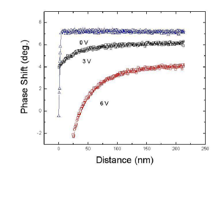
To test the sensitivity of the microscope in EFM mode, approach curves were measured using a grounded metallic sample and the tip biased at different voltages, as shown in Fig. 5. The -axis shows the distance from the sample to the tip and the -axis the phase shift with the tip biased at 0, 3 and 6 V. While the approach curve at 0 V bias shows an abrupt decrease at the vicinity of the contact point, the approach curve at higher bias voltages shows a monotonically decreasing phase shift over a large distance, which implies a long-range electrostatic Coulomb force.
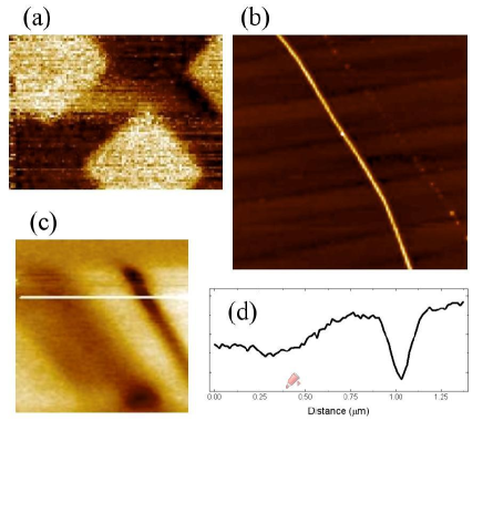
EFM measurements were performed on a standard Au grating sample and a boron nanowire sample. The topographic height at three edges of the area to be scanned were measured first. From these three measurements, the plane of the sample surface was determined. For the EFM measurement, the tip was scanned along this plane 100 nm above the sample surface plane, i.e., in constant height mode, and the phase of the tuning-fork oscillation was recorded. Figure 6(a) shows the EFM image of the Au grating at room temperature in air. The scanned area is 12 8.4 m2. This sample is metallic and has rectangular shaped areas. Since the tip was scanned at a large constant height, the contrast in the image comes from the electrostatic force difference experienced by the tip between the metallic and insulating regions of the sample. Figure 6(b) shows a topographic image of boron nanowires on Si substrate taken with our tuning-fork AFM. Images of two wires are seen, with the image of the thinner wire on the left barely visible. In the EFM image of the sample (Fig. 6(c)), both wires show up clearly, implying that they are conducting. The image of the narrower wire is now quite distinct: indeed, the contrast of the narrow wire in the EFM image is higher than that of the wider wire. This can be understood as arising from the fact that the narrower dimensions of the wire make the resulting electric field larger. The line profile (Fig. 6(d)) along a line in the EFM image indicates the resolution of the EFM is of the order of 50 nm.
III.2 MFM measurements
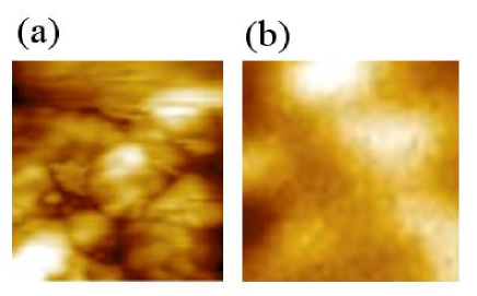
We performed low temperature MFM measurements at 77 K and 4.2 K. For the measurements at 77 K, the cryogenic insert was dipped into a liquid nitrogen dewar after evacuation of the vacuum can. In order to facilitate cooling of the device and microscope, 100 mTorr of helium exchange gas was introduced into the vacuum can, which resulted in the temperature of the tuning fork decreasing and stabilizing at 77 K within 15 min. The exact temperature of the tuning fork could be estimated from the shift in its resonant frequency.Bottom The resonant frequency of the tuning fork is very sensitive to temperature variations at 77 K, but becomes essentially independent of temperature around liquid helium temperatures. Figure 7 shows topographic (a) and MFM (b) images of the same area of a MnAs thin film grown by MBE technique. The areas of both scans are . MnAs is a room-temperature ferromagnet with a Curie temperature of 310 K.Chen The MFM images were obtained using lift-mode as described above Seo1 . No significant correspondence between the topographic and MFM images can be seen. Similar studies on MnAs film have been reported elsewhere.Engel-Herbert
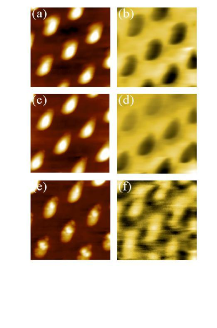
MFM measurements were also performed on SrRuO3 nanodot arraysRuzmetov at 4.2 K in the presence of a magnetic field by dipping the insert into a dewar equipped with a 3 T axial superconducting solenoid. SrRuO3 is a ferromagnetic perovskite with a transition temperature of 160 K, so a low temperature MFM is required to observe its magnetic properties. Topographic and MFM images were obtained simultaneously in 0, 1.5, and 3 T magnetic fields perpendicular to the plane of the film (Figure 8). The images without magnetic field (a,b) are similar to previous results.Ruzmetov When a 1.5 T magnetic field was applied, the upper-left corner of the MFM image (d) became blurred and the lower-right corner clear. At higher magnetic field (3 T), the MFM image (f) shows a completely different pattern. A further analysis of this phenomena is beyond the scope of this report.
IV Conclusion
In conclusion, we have developed a low-temperature SFM using a quartz tuning fork. An easy and economic way to build a low temperature coarse approach mechanism using a single PZT tube actuator was shown. We have demonstrated room temperature EFM imaging of conductive nanostructures and MFM imaging of MnAs thin films and SrRuO3 nanodots at 77 K and 4.2 K respectively. A tuning-fork based SFM is a promising candidate for millikelvin temperature SFM, because of its low power dissipation, simple design, and high spatial resolution.
This work was supported by the NSF through grant number ECS-0139936. We thank A. K. Gupta and K.-W. Ng for helpful discussions about the low temperature coarse approach mechanism. We also thank R. S. Ruoff, D. Dikin, J. H. Song, J. B. Ketterson, D. Ruzmetov, and C.-B. Eom for providing samples.
References
- (1) F. J. Giessibl, S. Hembacher, H. Bielefeldt, and J. Mannhart, Science 289, 422 (2000).
- (2) M. Herz, F. J. Giessibl, and J. Mannhart, Phys. Rev. B 68, 045301 (2003).
- (3) F. J. Giessibl, Appl. Phys. Lett. 76, 1470 (2000).
- (4) A. Moser, H. J. Hug, I. Parashikov, B. Stiefel, O. Fritz, H. Thomas, A. Baratoff, H. -J. Güntherodt, and P. Chaudhari, Phys. Rev. Lett. 74, 1847 (1995).
- (5) W. Allers, A. Schwarz, U. D. Schwarz, and R. Wiesendanger, Rev. Sci. Instrum. 69, 221 (1998).
- (6) C. W. Yuan, E. Batalla, M. Zacher, A. L. de Lozanne, M. D. Kirk, and M. Tortonese, Appl. Phys. Lett. 65, 1308 (1994).
- (7) A. Volodin, K. Temst, C. Van Haesendonck, and Y. Bruynseraede, Rev. Sci. Instrum. 71, 4468 (2000).
- (8) J. Rychen, T. Ihn, P. Studerus, A. Herrmann, and K. Ensslin, Rev. Sci. Instrum. 70, 2765 (1999).
- (9) N. G. Patil and J. Levy, Rev. Sci. Instrum. 73, 486 (2002).
- (10) A. Kramer, J.-M. Segura, A. Hunkeler, A. Renn, and B. Hecht, Rev. Sci. Instrum. 73, 2937 (2002).
- (11) K. R. Brown, L. Sun, and B. E. Kane, Rev. Sci. Instrum. 75, 2029 (2002).
- (12) Anjan K. Gupta and K.-W. Ng, Rev. Sci. Instrum. 72, 3552 (2001).
- (13) S. H. Pan, E. W. Hudson, and J. C. Davis, Rev. Sci. Instrum. 70, 1459 (1999).
- (14) easyPLL manufactured by Nanosurf AG in Switzerland.
- (15) Y. Seo, P. Cadden-Zimansky, and V. Chandrasekhar, Appl. Phys. Lett. 87, 103103-1 (2005).
- (16) Y. Seo, W. Jhe, and C. S. Hwang, Appl. Phys. Lett. 80, 4324 (2002).
- (17) H. Edwards, L. Taylor, W. Duncan, and A. J. Melmed, J. Appl. Phys. 82, 980 (1997).
- (18) V. E. Bottom, Introduction to Quartz Crystal Unit Design (Van Nostrand Reinhold, New York, 1982) p. 145.
- (19) X. Chen, M. Na, M. Cheon, S. Wang, H. Luo, B. D. McCombe, X. Liu, Y. Sasaki, T. Wojtowicz, J. K. Furdyna, S. J. Potashnik and P. Schiffer, Appl. Phys. Lett. 81, 511 (2002).
- (20) R. Engel-Herbert, J. Mohanty, A. Ney, T. Hesjedal, L. Daweritz, and K. H. Ploog, Appl. Phys. Lett. 84, 1132 (2004)
- (21) D. Ruzmetov, Y. Seo, L. J. Belenky, D. -M. Kim, X. Ke, H. Sun, V. Chandrasekhar, C. -B. Eom, M. S. Rzchowski, and X. Pan, Adv. Mater. 17, 2869 (2005).