Spin precession in inversion-asymmetric two-dimensional systems
Abstract
We present a theoretical method to calculate the expectation value of spin in an inversion-asymmetric two-dimensional (2D) system with respect to an arbitrarily spin-polarized electron state, injected via an ideal point contact. The 2D system is confined in a [001]-grown quantum well, where both the Rashba and the Dresselhaus spin-orbit couplings are taken into account. The obtained analytical results allow more concrete description of the spatial behaviors of the spin precession caused by individually the Rashba and the Dresselhaus terms. Applying the calculation on the Datta-Das spin-FET, whose original design considers only the Rashba effect inside the channel, we investigate the possible influence due to the Dresselhaus spin-orbit coupling. Concluded solution is the choice of [110], in particular [110], as the channel direction.
pacs:
72.25.Dc; 71.70.Ej; 85.75.HhI Introduction
The Datta-Das spin field-effect transistor (spin-FET) 1 , though not yet experimentally realized, has stimulated plenty of research on related topics in the emerging field of semiconductor spintronics 2 ; 3 . The original design contains a two-dimensional electron gas (2DEG) channel, bridged by ferromagnetic spin injection source and detection drain contacts. Considering the structure inversion asymmetry (SIA) of the confinement potential, a spin-orbit (SO) coupling due to the Rashba effect 4 generates an effective magnetic field, which is always perpendicular to the electron propagation inside the channel. Through an applied gate voltage, the strength of the confinement potential and the corresponding Rashba field may be varied, thus tuning the spin precession rate for the injected electrons, transiting along the 2DEG channel. The stronger the gate voltage applied, the higher the spin precession rate is. Therefore, the spin orientation angle for the electrons arriving at the end of the channel, and hence the resulting current, is theoretically tunable via the applied gate voltage. Such proposed device is expected to serve as a field-effect transistor based on the electron spin, and hence called Datta-Das spin-FET.
The principal advantage of such a spin-FET is that it may switch faster than the traditional one since the charge redistribution is no more involved. However, realization of the Datta-Das spin-FET faces basic challenges, including 3 : (i) effective controllability of the Rashba SO coupling strength , (ii) long spin-relaxation time in 2DEGs, (iii) uniformity of , and (iv) more efficient spin injection rate. So far, the former two conditions have been basically satisfied in experiments 5 ; 6 , while the latter two remain to be solved. Furthermore, recent attention has even been put on the possible influence due to the bulk inversion asymmetry (BIA) 7 of the underlying crystal containing the 2DEG, which is neglected in the original design of Datta and Das 8 .
Previously, a great part of attention has been put on the spin injection rate for the ferromagnet-2DEG junction structures 9 ; 10 . To examine the feasibility of the Datta-Das spin-FET theoretically and more generally, however, we turn to the fundamental problem, namely, the spin precession due to space inversion asymmetry in two-dimensional systems.
In this paper, we begin with a quantum mechanical approach of detection for an arbitrarily polarized and perfectly injected electron spin inside a 2DEG channel, with both the SIA and BIA involved. Applying such techniques we analyze the spatial behaviors of the spin precession due to individually the SIA, the BIA, and simultaneously the SIA and BIA. With proper orientation of spin injection, we can thus examine the 2DEG channel of the Datta-Das spin-FET and see what influence the additionally considered BIA may bring.
II Quantum-mechanical spin detection
The logic of how the space inversion asymmetry can lead to spin precession is quite simple and clear. Let us summarize as follows. From Kramers theorem, one has degenerate energy bands in solids when no external magnetic field is applied 11 . With space inversion symmetry, i.e., the energy bands are degenerate along for a certain spin state or : , one is led to the Kramers degeneracy . In other words, a zero-field spin-splitting will exist intrinsically when the crystal does not own the space inversion symmetry. The spin-splitting, though does not stem from the applied magnetic field, can be ascribed to an effective magnetic field, leading to spin precession about the field direction.
Put in another way, the structure inversion asymmetry of the crystalline structure is the key to the spin precession, and hence the principle of the Datta-Das spin-FET. As mentioned in the previous section, the SIA of the confinement potential plays the crucial role in the Datta-Das spin-FET for gate-voltage tunability and can be described in the linear Rashba model 4 by
| (1) |
choosing the 2DEG growth direction [001] along . Symbols and are the well-known Pauli matrices. When the 2DEG is confined in a zinc-blend-based semiconductor, the BIA (the Dresselhaus term 7 ) described by the linear term
| (2) |
must be further considered. Parameter depicts the strength of the Dresselhaus SO coupling and is material-specific. Note that the contribution of the term in the Dresselhaus SO coupling is neglected since the 2DEG plane is assumed to be thin. The full Hamiltonian describing the electron
| (3) |
in the effective mass approximation then leads to the eigenfunctions
| (4) |
with
| (5) |
corresponding to the eigenenergies
| (6) |
where the composite SO strength is defined by
| (7) |
Note that the space part and the spin part in the eigenfunction Eq. (4) are entangled, and can not be expressed as direct products. By this we mean that the spinor always contains the information of the wave vector, i.e., the electron propagation angle .
Let us now inject a spin-polarized electron described by
| (8) |
on in 2DEG. Expanding Eq. (8) in terms of the Rashba-Dresselhaus eigenstates Eq. (4), we have
| (9) |
where the expansion coefficients are given by . When the electron is spatially evolved to another point, say , the state ket then reads
| (10) |
which is the consequence of operating the translation operator . When factoring out a phase , which does not affect any physical quantity, we can express the state ket evolved from to as
| (11) |
where we have utilized the fact that the difference of the Fermi momenta along a certain direction, say , is a fixed value
| (12) |
and the phase difference is defined by
| (13) |
Using Eq. (11) and setting , the expectation values of spin operators , , and can be obtained as
| (14) |
The above spin vector expression is suitable for an inplane-polarized spin [Eq. (8)] injected on , and is functions of detection position , Rashba and Dresselhaus coupling strengths and , and the orientation angle of spin polarization . When considering the general case with arbitrary spin polarization for the injected electrons, one need only replace the spinor expressed in Eq. (8) by
| (15) |
where is the polar angle.
III Spatial behaviors
We now demonstrate the spatial behaviors of the spin precession due to different mechanisms of inversion asymmetry by using the analytical formulae Eq. (14). Consider a 2DEG plane with spin injection on the center of the plane. The polarization of the injected spin is set parallel to [100]. Assume that the electron possess a conserved wave vector and is free to move in the 2DEG plane along any crystallographic direction.
Let us begin with the Rashba case, i.e., only the SIA mechanism of inversion asymmetry is present. The well-known Rashba field is circularly polarized and the corresponding spin precession is shown in Fig. 1(a). Such a circular polarization of the induced effective magnetic field manifests that the Rashba SO interaction is independent of the crystallographic direction, and is invariant under rotation about the normal axis of the 2DEG plane. The spatial behavior of the injected spin precessing with space (rather than time) and rotating about the perpendicular field [red bold arrows in Fig. 1(a), and also in (b) and (c)] is clearly observed. Since the Rashba field is always normal to the electron wave vector, the injected spinexhibits an upright precession when the electron propagates parallel to the polarization of the injected spin, while the precession is suppressed when propagating perpendicular to the injected spin.

In the pure Dresselhaus case [Fig. 1(b)], the injected spin encounters another type of effective magnetic field, and hence the spatial behavior is quite different from the Rashba one. The generated field directions are no more perpendicular to the wave vector, except those along [110], on which the Dresselhaus spin precession exhibits the same spatial behavior with the Rashba one. In addition, the rotational invariance about z, contrary to the Rashba case, is broken, and the crystallographic direction dependence hence comes in.
Indeed, in the composite case shown in Fig. 1(c), where we set the coupling ratio , the total effective magnetic field remains perpendicular to the electron propagation along [110]. In the design of the Datta-Das spin-FET, one can see that if the channel direction is arbitrarily chosen, e.g., along [100], the spin precession may be slanted, thus lowering the efficiency of the tunability of the resulting current via the gate voltage.
IV Datta-Das spin-FET
To be more specific on the influence by the BIA on the Datta-Das spin-FET, let us now consider an ideal one-dimensional channel confined in a zinc-blende type semiconductor, where both the SIA and BIA are present. Setting the Dresselhaus SO strength , we analyze the projection of the spin vector on the drain magnetization (set parallel with the channel direction as the design of the Datta-Das spin-FET) for respectively the -dependence and position dependence, along [100] and [110].
In Fig. 2(a), the spin detection point is fixed on the end of the channel with the Rashba SO strength tuned from 0 to , which corresponds to typical values for InGaAs 2DEGs 10 . The channel length is set and the effective mass is times the electron rest mass 10 . Clearly, only the [110] curves exhibit maximized oscillation due to the upright spin precession. When choosing the channel direction as [100], the electron encounters tilted effective magnetic field, and the oscillation amplitude decreases, until the SIA strength is much stronger than the BIA. This may lower the spin signal of the Datta-Das transistor quite severely and hence only [110] are the proper candidates for the channel direction of the Datta-Das spin-FET.
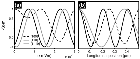
Due to the anisotropy of the spin-splitting strength [Eq. (7)], the precession period, in fact, varies with the channel direction. For and of the same sign, the spin-splitting along [110] is strongest: while that along [1-10] is weakest: . Fixing the Rashba strength as , we analyze the spin projection on the longitudinal position varied from 0 to . Again, the amplitude of the [100] curve does not reach the maximum since the precession is slanted, while the [110] curves do. However, the precession period for the [1-10] curve is almost twice the [110] curve since the SO coupling ratio along these two directions is .
V Conclusion
In conclusion, we have derived the analytical expression for the spin expectation of a point-injected electron, using a standard quantum mechanical approach. The obtained formulae are useful for analyzing the spatial behaviors of the spin precession caused by individually the SIA and the BIA, and even the spin vectors in the whole 2DEG channel, considering both the SIA and BIA mechanism. The dependence of the detection position, SO coupling strengths, and orientation angle of the injected spin-polarization are included in the formulae, and hence provides a wide variety to investigate the feasibility of the Datta-Das transistor for more details.
In the analysis of the spin precession behaviors, the Rashba case shows rotation symmetry about the normal axis of the 2DEG plane, while this symmetry is broken in the Dresselhaus case. Furthermore, we found that the injected spin always encounters a perpendicular effective magnetic field along [110] in the composite case, and these two directions are therefore candidates for the Datta-Das spin-FET channel directions.
By considering an ideal one-dimensional channel with injected spin polarized parallel to the channel direction, we also re-examined the influence due to the BIA on the Datta-Das spin-FET. We demonstrated the significance of proper choice of the channel direction. Choosing directions other than [110] may severely decrease the spin signal collected by the drain contact. In addition, electrons transiting along [110] are found to encounter stronger SO coupling than along [1-10] in the case of . Thus we conclude that [110] may be the best candidate for the channel direction of the Datta-Das spin-FET.
Acknowledgements.
This work was supported by the Republic of China National Science Council Grant No. 94-2112-M-002-004.References
- (1) S. Datta and B. Das, Appl. Phys. Lett. 56, (1990) 665.
- (2) Semiconductor Spintronics and Quantum Computation, edited by D. D. Awschalom, D. Loss, and N. Samarth (Springer, Berlin, 2002).
- (3) Igor Žutić, Jaroslav Fabian, and S. Das Sarma, Rev. Mod. Phys. 76, (2004) 323.
- (4) Yu. A. Bychkov and E. I. Rashba, JETP Lett. 39, (1984) 78.
- (5) J.M. Kikkawa and D.D. Awschalom, Phys. Rev. Lett. 80, (1998) 4313.
- (6) J. Nitta, T. Akazaki, H. Takayanagi, and T. Enoki, Phys. Rev. Lett. 78, (1997) 1335.
- (7) G. Dresselhaus, Phys. Rev. 100, (1955) 580.
- (8) A. Łusakowski, J. Wróbel, and T. Dietl, Phys. Rev. B 68, (2003) R081201.
- (9) P. R. Hammar, B. R. Bennett, M. J. Yang, and M. Johnson, Phys. Rev. Lett. 83, (1999) 203.
- (10) C.-M. Hu and T. Matsuyama, Phys. Rev. Lett. 87, (2001) 066803.
- (11) C. Kittel, Quantum Theory of Solids, Wiley, New York, 1963.
- (12) Y. Sato, T. Kita, S. Gozu, and S. Yamada, J. Appl. Phys. 89, (2001) 8017.