Negative refraction and plano-concave lens focusing in one-dimensional photonic crystals
Abstract
Negative refraction is demonstrated in one-dimensional (1D) dielectric photonic crystals (PCs) at microwave frequencies. Focusing by plano-concave lens made of 1D PC due to negative refraction is also demonstrated. The frequency-dependent negative refractive indices, calculated from the experimental data matches very well with those determined from band structure calculations. The easy fabrication of one-dimensional photonic crystals may open the door for new applications.
Negative refraction Veselago and related phenomena such as flat lens imaging Pendry ; Luo02 ; Parimi03 and plano-concave lens focusing Vodo05 have attracted a lot of attention in physics and engineering. Negative refraction allows subwavelength imaging Luo03 and focusing of far field radiation by concave rather than convex surfaces with the advantage of reduced aberration Schurig ; Chen06 for the same radius of curvature. Negative refraction has been realized in two- and three-dimensional structures in metamaterials Shelby ; Parazzoli and photonic crystals Parimi04 ; LuZ . But negative refraction has not yet been demonstrated in one-dimensional (1D) photonic crystals (PCs).
In this letter we present a study of left-handed electromagnetism in 1D PCs at microwave frequencies. Negative refraction is achieved in the second band of the 1D PCs. Focusing of plane wave radiation by plano-concave lenses made of 1D PC is also demonstrated. The inverse experiment, in which the lens produces plane waves from a point source placed at the focal length, at the same frequency of operation, is confirmed as well. The frequency-dependent negative refractive indices, calculated from the experimental data matches very well with those determined from band structure calculations. The easy fabrication of 1D PCs may open the door for new applications.
The experiments were carried out in a parallel-plate waveguide of height cm and size ft2. For frequency below 12 GHz, the excitation in these quasi-2D system is the transverse magnetic (TM) modes with the electric field in the vertical direction. The electric field of the microwaves is scanned using a monopole antenna attached to a X-Y robot in the frequency window 3-11.5 GHz. An HP-8510C network analyzer is used for measuring the transmission characteristics. A schematic diagram of the experimental setup is shown in Fig. 1.
Alumina bars with permittivity were laid out to form prisms of right angle triangles. The bars have a height cm and width cm. The refraction experiments were performed on two PC prisms. The first prism (PC1) has lattice constant cm and the incident angle 45∘ while the second one (PC2) has cm and the angle 51∘. All bars have a perpendicular cut instead of a slanted one, as numerical simulations Lu06 show that a perpendicular cut reduces the modulations of the outgoing waves, partly due to the absence of sharp corners. A plane wave incident normally to one surface is refracted by the hypotenuse of the 1D PC prism as shown in Fig. 1, defined as the surface of refraction.
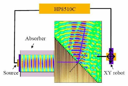
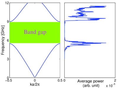
The 1D PC is a model that is exactly soluble Joannopoulos . For the TM modes, it is just the Kronig-Penny model Kronig with an energy dependent potential. The band structure for the TM modes for the filling factor is shown in Fig. 2. A band gap is located between 5.55-8.9 GHz. The second pass band is between 8.9-12.7 GHz and has negative refractive index. The refraction of a microwave beam by the PC1 prism at 10.55 GHz is shown in Fig. 1. By fitting the outgoing beam with a plane wave, the wave front is determined and an effective index is obtained using Snell’s law.
Although positive refraction is predicted for both PC prisms in the first band, the incident angle for each PC prism exceeds the corresponding Brewster angle, resulting in total internal refraction. The average power of the scanned points is plotted as a function of frequency in Fig. 2. While the outgoing signal is very weak for the total internal reflection and band gap frequency regions, an interesting observation is that there is a strong leaking from the prism near the edges of the band gap.
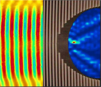
The same alumina bars were used to form a plano-concave lens of 1D PC. The concave radius of the lens is cm. A sharp focal point is located at 6.15 cm away from the curved surface when a microwave beam incidents at frequency 9.5 GHz. From left to right in Fig. 3, the incoming plane wave, a real picture of the PhC lens and the emerging mapped field are shown. Clear focusing is observed in the frequency range 9.2-11.5 GHz.
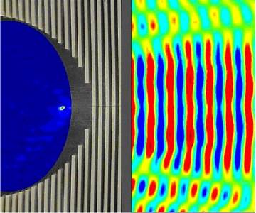
An inverse experiment in which a point source is placed at the observed focal point of the lens at a single frequency is also carried out. As shown in Fig. 4, a circular wave front from the point source after passing through the lens emerges as a plane wave. These two remarkable results validate the behavior of a left-handed plano-concave lens.
The refractive index of the lens can be estimated using the lens equation which is valid for thin plano-concave and plano-convex lenses in the geometric optics limit. Here is the radius of curvature and is the focal length. Using this equation we get at 9.5 GHz for the lens shown in Fig. 3. A real focus by a plano-convex lens is achieved with and while for the plano-concave lens with and .
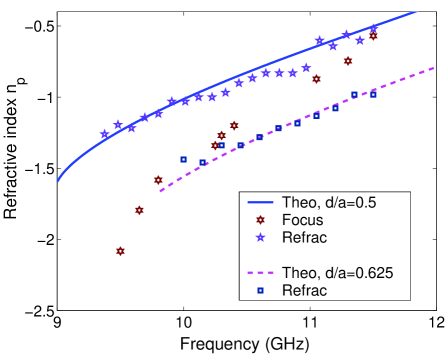
The refractive indices determined from the prism refraction experiments (PC1 and PC2) and the plano-concave lens one are shown in Fig. 5. Very good agreement with those calculated from the band structure is observed. The index determined from the focusing experiment fits better with theoretical results as the frequency is increased. This may be due to the reduced finite-size effect and aberration at higher frequency.
The nature of the left-handed electromagnetism and focusing can be understood from the dispersion characteristics of the 1D PC. From the band structure shown in Fig. 2, it can be deduced that in the second band the wave vector is in opposite direction to group velocity, , resulting in negative refraction in the second band and correspondingly negative refractive indices Parimi04 .
Bandwidth for obtaining a sharp focus point is a crucial parameter for applications of the left-handed lenses. Due to the resonant nature of the metamaterial the bandwidth is usually restricted to a narrow region and the dispersion is strong Parazzoli04 . The PC1 reveals a wide bandwidth of 3.8 GHz, which is 35% at the current operating frequencies. The weaker dispersion in the PC makes it a better candidate for focusing a pulse or broadband radiation.
The present PC lens with negative refraction has several advantages when compared to the one with positive refraction. Lenses with reduced geometric aberrations produce sharper image with enhanced resolution and find numerous applications. Larger radius of curvature gives the advantage of reduced aberration in the image formed. A PC lens having the same focal length as that of a conventional lens weighs far less, and is attractive to space applications. The tailor made refractive index achievable in PC materials Vodo04 allows further control on the focal length and thereby helps to reduce the length of the optical systems.
In conclusion the feasibility of designing a 1D broadband left-handed PC lens is experimentally demonstrated. Negative refraction of plane waves and plano-concave lens focusing is achieved by 1D PCs. The focal length follows the standard laws of geometrical optics combined with negative refraction. The measured values of refractive indices of the lens are in excellent agreement with those determined from band structure calculations from both refraction and focusing experiments. Earlier work has shown that 1D PCs can be used as omnidirectional reflectors Fink ; Ibanescu . The observed negative refraction in 1D PC reported here, adds a new feature to these simple systems.
We thank E. Brownell for assistance with the experiments. This work was supported by the Air Force Research Laboratories, Hanscom AFB and NSF grant No. PHY-0457002.
References
- (1) V. Veselago, Soviet Physics USPEKHI 10, 509 (1968).
- (2) J. B. Pendry, Phys. Rev. Lett. 85, 3966 (2000).
- (3) C. Luo, S. G. Johnson, ans J. D. Joannopoulos, Phys. Rev. B 65, 201104 (2002).
- (4) P. V. Parimi, W. T. Lu, P. Vodo, and S. Sridhar, Nature (London) 426, 404 (2003).
- (5) P. Vodo, P. V. Parimi, W. T. Lu, and S. Sridhar, Appl. Phys. Lett. 86, 201108 (2005).
- (6) C. Luo, S. G. Johnson, J. D. Joannopoulos, and J. B. Pendry, Phys. Rev. B 68, 045115 (2003).
- (7) D. Schurig and D. R. Smith, Phys. Rev. E 70, 065601 (2004).
- (8) J. Chen, C. Radu, and A. Puri, Appl. Phys. Lett. 88, 071119 (2006).
- (9) R. A. Shelby, D. R. Smith, and S. Schultz, Science 292, 77 (2001).
- (10) C. G. Parazzoli, R. B. Greegor, K. Li, B. E. C. Koltenbachand, and M. Tanielian, Phys. Rev. Lett. 90, 107401 (2003).
- (11) P. V. Parimi, W. T. Lu, P. Vodo, J. Sokoloff, J. S Derov, and S. Sridhar, Phys. Rev. Lett. 92, 127401 (2004).
- (12) Z. Lu, J. A. murakowski, C. A. Schuetz, S. Shi, G. J. Sneider, and D. W. Prather, Phys. Rev. Lett. 95, 153901 (2005).
- (13) W. T. Lu and S. Sridhar, unpublished.
- (14) J. D. Joannopoulos, R. D. Meade, and J. N. Winn, Photonic Crystals: Molding the Flow of Light, Princeton Univ. Press (1995).
- (15) R. Kronig, and W. G. Penney, Proc. R. Soc. A 130, 499 (1931).
- (16) C. G. Parazzoli, R. B. Greegor, J. A. Nielsen, M. A. Thompson, K. Li, A. M. Vetter, M. H. Tanielian, and D. C. Vier, Appl. Phys. Lett. 84, 3232 (2004).
- (17) P. Vodo, P. V. Parimi, W. T. Lu, S. Sridhar, and R. Wing, Appl. Phys. Lett. 85, 1858 (2004).
- (18) Y. Fink, J. N. Winn, S. Fan, C. Chen, J. Michel, J. D. Joannopoulos, and E. L. Thomas, Science 282, 1679 (1998).
- (19) M. Ibanescu, Y. Fink, S. Fan, E. L. Thomas, and J. D. Joannopoulos, Science 289, 415 (2000).