Mechanical control of spin-orbit splitting in GaAs and InGaAs epilayers
Abstract
Time-resolved Kerr rotation spectroscopy as a function of pump-probe distance, voltage and magnetic field is used to measure the momentum-dependent spin splitting energies in GaAs and InGaAs epilayers. The strain of the samples can be reproducibly controlled in the cryostat using three- and four-point bending applied with a mechanical vise. We find that the magnitude of the spin splitting increases linearly with applied tension and voltage. A strain-drift-diffusion model is used to relate the magnitude of the measured spin-orbit splitting to the amount of strain in the sample.
pacs:
71.70.Ej, 71.70.Fk, 72.25.Dc, 72.25.RbPotential applications in spintronics wolf01 and quantum information processing awsch02 rely upon an understanding of the effect of electric fields and strain on electron spins. Strain reduces the symmetry of a crystal, which introduces momentum k-linear terms to the Dresselhaus dres and Bychkov-Rashba rashba spin splittings. These strain-induced effective magnetic fields can be used to generate electron spin polarization electrically katoPRL and coherently manipulate spins using electric fields and in the absence of magnetic fields kato04 , but they also contribute to more efficient spin relaxation knotz . In addition, recent steady-state measurements crooker05 ; beck have shown that the spatial period of strain-induced spin precession is independent of the applied electric field, which demonstrates the robustness of strain-induced spin precession for applications in functional spin-based devices.
Here we employ mechanical three- and four-point bending to tune the tensile strain of GaAs and InGaAs epilayers while performing low-temperature time-resolved magneto-optical spectroscopy to determine the magnitude of the strain-induced spin splitting. The samples are contacted so that an in-plane electric field can be applied to impart an average drift velocity to the optically-excited electron spins. Kerr rotation measurements as a function of magnetic field and pump-probe distance are performed for different applied electric fields, and we observe that the spin splitting increases with increasing drift velocity and tensile strain. Unlike previous measurements that introduced strain through heterostructure engineering and lattice-mismatched growth kato04 , these measurements are able to map out the strain dependence in a single sample and without the complications of strain relaxation. The vise geometry allows for repeatable tensioning of samples and precise control over the strain level.
The samples are grown using molecular beam epitaxy on semi-insulating (001) GaAs substrates. We examine both n-doped GaAs and InGaAs epilayers. The GaAs samples are comprised of 100 nm undoped GaAs buffer layer, 400 nm Al0.7Ga0.3As, and a 500 nm Si-doped GaAs epilayer. Samples with carrier densities of cm-3 and cm-3 were measured, but since they exhibit qualitatively similar behavior, we show only data for the cm-3 -GaAs sample in this paper. The InGaAs sample is composed of 300 nm of growth-interrupted GaAs buffer layer, 500 nm of Si-doped In0.04Ga0.96As with a carrier concentration of cm-3, and 100 nm of undoped GaAs. The lattice constant of the InGaAs layer is matched to that of GaAs, as confirmed using x-ray diffraction. Since InGaAs has a larger natural lattice constant than GaAs, the InGaAs layer is compressively strained in-plane as grown.
The samples are patterned into mesas using photolithography and a chemical wet etch and then contacted using annealed Ni/AuGe [Fig. 1(a)]. The channels have a width = 120 m and length = 310 m between the contacts and are aligned such that an electric field E = V/ can be applied along either the [10] () or [110] () directions. The samples are then mounted into either a three- or four-point mechanical bending vise. While the four-point bending geometry produces strain that is uniform between the central two points strain , higher maximum values of strain can be achieved in the three-point geometry before structural failure occurs. In the case of the four-point bending, the mesas are patterned far from the four contact points, minimizing local strain variations. The sample is cooled to a temperature T = 60 K, at which nuclear polarization is negligible kikk00 . For the field-dependent measurements, a magnetic field is applied along . A cross-section of the measurement geometry is shown in Fig. 1(b). The vise is tightened along the direction, introducing tensile strain along . The optical measurements are performed along and measure the spin polarization along [001].
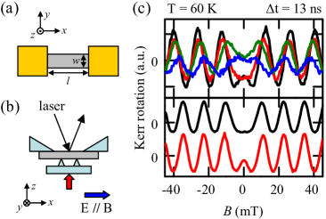
Time-resolved Kerr rotation spectroscopy crooker97 is used to monitor the electron spin dynamics in the samples. In this technique, a Ti:Sapphire laser, tuned to the absorption edge of the material that we wish to probe (wavelength = 818 nm for GaAs and = 850 nm for In0.04Ga0.96As), produces a train of 250 fs pulses at a repetition rate of 76 MHz, which are split into a pump beam (2 mW) and a probe beam (200 W) with 30 m diameters. The pump pulse is circularly-polarized and excites a spin-polarized electron population in the epilayer. A linearly-polarized probe pulse is incident on the sample at time t later, which is controlled using a mechanical delay line. The electron spin polarization in the sample is measured by detecting the change in the polarization axis, or Kerr rotation, of the reflected probe beam. Time-resolved measurements at temperature T = 60 K and an applied magnetic field B = 0.2 T show that the electron g-factor is -0.43 for the GaAs epilayer and -0.48 for the InGaAs epilayer and that the transverse spin coherence time is 40 ns for GaAs and 3 ns for the InGaAs sample. For the spatially-resolved measurements, a stepper motor-driven mirror changes the spatial separation between the pump and probe beams kikk99 . The applied electric field causes the spins to drift with an average velocity and imparts a non-zero average momentum k to the electron spin packet.
In order to determine the k-dependent internal magnetic field Bint, we measure Kerr rotation as a function of the applied magnetic field Bext at t = 13 ns for various E and pump-probe distances. The presence of Bint modifies the symmetric cosinusoidal field-dependent signal kato04 ; kikk99 ; kalevich . When Bint is along the same direction as Bext, the signal becomes centered about -Bint, but if Bint and Bext are perpendicular, as is the case when the electric field and Bext are applied along the same direction, the data can be fit to the equation:
| (1) |
where is the amplitude, g the effective g-factor of the sample, the Bohr magneton, and is Planck’s constant over 2. For E = 32 V cm-1 and t = 13 ns, the center of the electron spin packet is observed to be at pump-probe separation = 38 m. Figure 1(c) (top) shows data for the GaAs sample for different amounts of tension applied using the four-point bending vise. We measure Kerr rotation in the channel for the unstrained case and for five increasing levels of strain, which we label as strained states 1 - 5. The vise is tightened by the same amount between each of these strained states. Increasing the strain in the GaAs sample decreases the signal amplitude and increases the spin precession frequency and Bint. The change in the amplitude is due to a decrease in the spin lifetime, which we confirm using time-resolved Kerr rotation. In contrast, measurements on InGaAs, shown in Fig. 1(c) (bottom), show that the application of tensile strain via the three-point bending vise leads to some relaxation of the compressive strain due to lattice mismatch. The Kerr rotation amplitude is increased, and Bint is decreased. Measurements were also performed on the cm-3 GaAs sample for channels where E was applied along and perpendicular to Bext and the direction of the tensile strain; in this geometry, Bint is parallel to Bext, and the values obtained for Bint were 22 smaller.
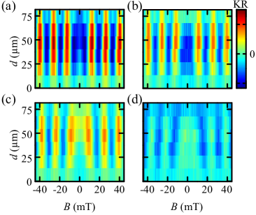
We explore the strain-dependent spin-orbit splitting in the GaAs sample as a function of electric field and pump-probe distance. In Figures 2(a)-(d), we show Kerr rotation as a function of applied magnetic field and pump-probe separation for strained states 2, 3, 4, and 5 for E = 32 V cm-1 and t = 13 ns. The color scale is the same for all four plots. Again, we observe that the spin precession period and amplitude decrease with strain and that an increase in Bint lowers the central peak. In these measurements, we also observe the effect of spin diffusion, which is manifest in the spatial dependence of Bint and is due to the spread in drift velocities of the spin packet.
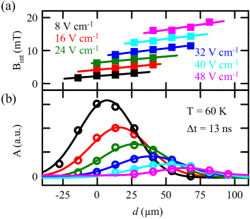
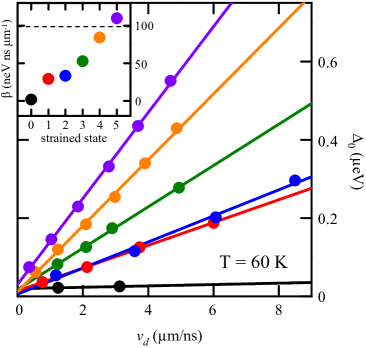
In order to characterize the voltage-dependence of Bint, we fit the amplitude as a function of with a Gaussian function to determine the center position of the spin packet . We then use the results of a linear fit of Bint to determine the value of Bint at for each voltage. In Figure 3, we show the data (symbols) and fits (lines) for and Bint for the GaAs sample for strained state 4 as a function of and for various values of E. From these fits, we obtain the spin-splitting energy = g Bint at the center of the spin packet as a function of , which is plotted in Fig. 4 for increasing amounts of strain in the cm-3 GaAs sample. As observed previously kato04 , the data can be fit to a line, where the slope = / can be used to characterize the observed effect. We plot for each of the strained states in the inset of Fig. 4 and observe that increases for increasing amounts of applied tension. In comparison, previous measurements kato04 on GaAs strained by the removal of the underlying substrate showed that = 99 neV ns m-1. Similar measurements of the InGaAs sample reveal that = 72 neV ns m-1 when unstrained and = 40 neV ns m-1 when strained with the three-point bending vise.
Although we tightened the mechanical vise by the same amount between each of the strained states, slip and play in the vise make it difficult to determine the amount of bending and strain in the sample by the mechanical displacement . In order to estimate the amount of strain for each of the strained states, we solve a strain-drift-diffusion model crooker05 ; hruska to determine the spatial spin precession period as a function of . Although this model was developed for steady-state measurements, as described in Ref. [crooker05, ], using the spatial spin precession period kato05 SPP = 2 / , we can relate and . The model parameters used are similar to those used in Ref. [crooker05, ; hruska, ] with the exception of the spin diffusion constant . A value of = 283 V/cm2 was obtained from the measurements in Fig. 3. The strain-drift-diffusion equations are
| (2) |
| (3) |
| (4) |
where the operators - are defined as follows,
| (5) |
| (6) |
| (7) |
| (8) |
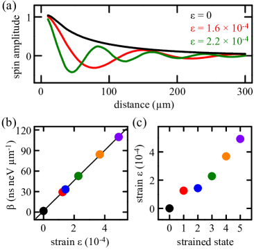
Here is the x,y,z component of electron spin polarization, is a Gaussian source function with a FWHM of 30 m, is the spin diffusion constant, is the mobility, is the spin relaxation time, E is the applied electric field, B is the applied magnetic field, = m* /, = g Bi, m* is the electron effective mass, and is the strain. We assume a value for the spin-strain coupling coefficient C3 = 4.0 eV , as in Ref. [hruska, ]. The equations are solved over a 1 1 mm field using a finite element method. For the strain calibration, the external applied magnetic field was set to zero, and an electric field of 33 V cm-1 was used. We obtain solutions of the spin polarization as a function of position for varying values of between 0 and 0.001. Figure 5(a) shows three line cuts of taken along the direction of the electric field for different solutions with = 0, 1.6, and 2.2 10-4. We fit these line cuts to determine the spatial spin precession frequency as a function of . A linear fit of as a function of yields a slope of 22.27 0.96 in units of per 10-4 unit strain. Figure 5(b) shows as a function of . This relation allows us to assign strain values to all six tension states using their measured values of [Fig. 5(c)].
In summary, we have performed quantitative measurements of the spin-splitting energy as a function of voltage and strain on samples mounted in a mechanical vise. Using a strain-drift-diffusion model, we are able to estimate the strain in the devices and calibrate the observed spin-splitting. This spin-splitting can be used to locally and coherently manipulate electron spins and electrically drive spin resonance kato04 ; rashba03 .
We acknowledge support from AFOSR, DARPA/DMEA, NSF and ONR.
References
- (1) S. A. Wolf, D. D. Awschalom, R. A. Buhrman, J. M. Daughton, S. von Molnar, M. L. Roukes, A. Y. Chtchelkanova, and D. M. Treger, Science 294, 1488 (2001).
- (2) Semiconductor Spintronics and Quantum Computation, NanoScience and Technology, edited by D. D. Awschalom, N. Samarth, and D. Loss (Springer-Verlag, New York 2002).
- (3) G. Dresselhaus, Phys. Rev. 100, 580 (1955).
- (4) Y. A. Bychkov and E. I. Rashba, J. Phys. C 17, 6039 (1984).
- (5) Y. Kato, R. C. Myers, A. C. Gossard and D. D. Awschalom, Nature 427, 50 (2004).
- (6) Y. K. Kato, R. C. Myers, A. C. Gossard and D. D. Awschalom, Phys. Rev. Lett. 93, 176601 (2004).
- (7) H. Knotz, A. W. Holleitner, J. Stephens, R. C. Myers and D. D. Awschalom, cond-mat/0511562 (2005).
- (8) S. A. Crooker and D. L. Smith, Phys. Rev. Lett. 94, 236601 (2005).
- (9) M. Beck, C. Metzner, S. Malzer and G. H. Dohler, cond-mat/0504668 (2005).
- (10) E. J. Hearn, Mechanics of Materials (Butterworth Heinemann, Oxford, 3rd Ed. 1997), Vol. 1 and 2.
- (11) J. M. Kikkawa and D. D. Awschalom, Science 287, 473 (2000).
- (12) S. A. Crooker, D. D. Awschalom, J. J. Baumberg, F. Flack, and N. Samarth, Phys. Rev. B 56, 7574 (1997).
- (13) J. M. Kikkawa and D. D. Awschalom, Nature 397, 139 (1999).
- (14) V. K. Kalevich and V. L. Korenev, JETP Lett. 52, 230 (1990).
- (15) M. Hruska, S. Kos, S. A. Crooker, A. Saxena and D. L. Smith, Phys. Rev. B 73, 075306 (2006).
- (16) Y. K. Kato, R. C. Myers, A. C. Gossard and D. D. Awschalom, Appl. Phys. Lett. 87, 022503 (2005).
- (17) E. I. Rashba and Al. L. Efros, Appl. Phys. Lett. 83, 5295 (2003).