Phase coherent splitting of Bose-Einstein condensates with an integrated magnetic grating
Abstract
We report the phase coherent splitting of Bose-Einstein condensates by means of a phase grating produced near the surface of a micro-electronic chip. A lattice potential with a period of is generated by the superposition of static and oscillating magnetic fields. Precise control of the diffraction is achieved by controlling the currents in the integrated conductors. The interference of overlapping diffraction orders is observed after 8ms of propagation in a harmonic trap and subsequent ballistic expansion of the atomic ensemble. By analyzing the interference pattern we show a reproducible phase relation between the diffraction orders with an uncertainty limited by the resolution of the diffraction grating.
pacs:
03.75.Lm, 03.75.Dg, 39.20.+qAtom optics and matter wave interferometry have made enormous progress during the last years. Numerous experiments have been performed with Bose-Einstein condensates serving as phase coherent sources of atomic matter waves Kasevich (2002). As a part of these, diffraction from standing and moving optical lattice potentials has been demonstrated to preserve the condensate’s coherence properties and is now established as a versatile tool for coherent manipulation Hagley et al. (1999); Stenger et al. (1999); Kozuma et al. (1999); Simsarian et al. (2000); Bongs et al. (2001); Torii et al. (2000). The implementation of similar diffraction scenarios on atomic micro chips is thus one of the most intriguing challenges of integrated atom optics. It holds great promise for transportable, high precision inertial force and gravity sensors Kasevich (2002), and for building complex atom optical circuits, e.g. quantum registers for information processing Birkl and Fortágh (2007). Although Bose-Einstein condensates are routinely loaded into magnetic micro traps Fortágh and Zimmermann (2007), it is technically demanding to integrate atom optical elements on a chip that allows for coherent manipulation of matter waves. Recently, diffraction from optical Wang et al. (2005) and magnetic lattices Günther et al. (2005a), as well as dynamical splitting of condensates in double well potentials Shin et al. (2005); Schumm et al. (2005); Jo et al. (2007) have been studied on micro chips.
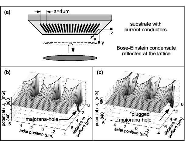
In this Letter, we demonstrate phase coherent splitting of Bose-Einstein condensates by means of diffraction on an integrated magnetic grating and realize a novel interferometric scheme. The magnetic grating is generated near the surface of micro fabricated current conductors (Fig.1).
We use static and oscillating magnetic fields for shaping and controlling the grating potential. Thereby, sensitive control of the populations of diffraction orders is achieved. Due to the relatively large lattice constant of and a correspondingly small recoil momentum, the diffraction orders of a condensate remain spatially overlapped during ballistic expansion. We observe their matter wave interference with a highly reproducible spatial fringe position. This provides experimental proof that diffraction from the magnetic grating preserves phase relation between the diffraction orders of a Bose-Einstein condensate. Magnetic gratings as described in this article will be important for phase coherent manipulation of matter waves in integrated atom optical circuits and for the realization of compact atom interferometers. In addition, microfabricted gratings extend the range of lattice constants accessible with optical standing wave fields Hagley et al. (1999). In particular, the size and the structure of the unit cell can be defined by the geometry of chip conductors.
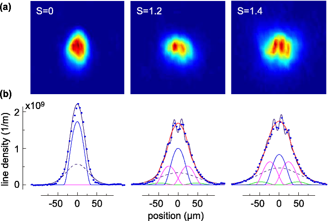
The experiment is illustrated in Fig.1a. An elongated Bose-Einstein condensates of about atoms in the , hyperfine ground state is prepared in a magnetic micro trap which is placed below the magnetic grating Günther et al. (2005b). The trap is characterized by the axial and radial oscillation frequencies of , and the offset field of in the trap center. Diffraction of the condensate is initiated by suddenly reducing the trap-surface separation by a controlled displacement. The condensate interacts with the lattice at the upper turning point of the radial center of mass oscillation inside the trap (y-direction) followed by a swing back towards the trap center. The trap is turned off 12ms after the displacement and the condensate is detected after 20ms of ballistic expansion by absorption imaging. The imaging axis is parallel to the lattice conductors (-direction). Diffraction is observed as a broadening of the cloud. Additionally, the emergence of interference fringes is observed (Fig.2).
The magnetic lattice potential is generated by a set of parallel current conductors on the chip surface. The wide gold conductors are micro fabricated on a silicon substrate with a separation of between nearest neighbors Günther et al. (2005b). Adjacent conductors carry constant currents of opposite sign: . The magnetic field of this wire configuration is superposed onto the trapping field including the offset field along . The resulting magnetic field modulus has a periodicity of along and the modulation amplitude decreases exponentially from the chip surface on the length scale of the lattice constant. Steep potential wells and hills emerge close to the lattice wires (Fig.1b).
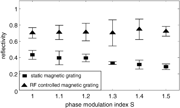
Diffraction on such a magnetic lattice potential Günther et al. (2005a) is associated with a significant loss of atoms (Fig.3). The dominant loss mechanism is due to the steep magnetic field gradients inside the potential wells of the lattice (Fig.1b). Atoms entering the wells are lost due to Majorana spin flips which result from the sudden break down of the adiabatic condition along the atom’s trajectory Sukumar and Brink (1997). Majorana loss may be tolerable if the experiment relies on a single diffraction pulse. Numerous interferometric schemes, however, require sequences of diffraction pulses Simsarian et al. (2000); Bongs et al. (2001); Torii et al. (2000) and the loss of atoms represents a limitation.
We eliminate losses by introducing radio frequency (rf) controlled adiabatic potentials Schumm et al. (2005); Lesanovsky (2006) to “plug” the Majorana hole and observe enhanced reflectivity on the magnetic lattice. An oscillating magnetic field of amplitude is superposed to the static field of the lattice. The polarization is parallel to the lattice conductors and the frequency of 585kHz is below the Larmor frequency of 610kHz corresponding to the offset field in the trap center. The resulting adiabatic lattice potential features wells of limited depth and the initially steep, attractive potential slopes are converted into repulsive potential walls (Fig.1c). We characterize the reduction of Majorana losses by detecting the total number of atoms reflected from the grating. The data is plotted against the phase modulation index (Fig.3). characterizes the population of the different diffraction orders as described below; e.g. for , the and diffraction orders have about the same population. The population of diffraction orders is varied by the displacement of the trap. The rf field is activated simultaneously to the displacement and is deactivated prior to turning off the magnetic trap for ballistic expansion. The rf controlled magnetic grating displays high reflectivity compared to its static counterpart. From this result we deduce that the motion of atoms is adiabatic in the rf controlled lattice potential. The high reflectivity diffraction grating allows phase coherent manipulation of Bose-Einstein condensates and the realization of a matter wave interferometer on a chip. The observation of a deterministic phase relation between diffraction orders of the condensate is the central result of this Letter.
The interaction of the condensate with the magnetic grating is described by the model of matter wave diffraction in the Raman-Nath regime Henkel et al. (1994). In particular, we assume a short interaction with a one-dimensional grating. This way the action of the grating is reduced to a phase modulation of the condensate wavefunction:
| (1) | |||||
| (2) |
Here, is the condensate’s density, is the lattice potential, and the wave vector is given by the lattice constant . characterizes a shift of the lattice position with respect to the center of the condensate. The amplitude accounts for the varying modulation depth during reflection as seen by the atom along its trajectory. The accumulated phase can be summarized using the phase modulation index .
The validity of this approximation is verified by numerical solution of the three-dimensional Gross-Pitaevskii equation et al. . It has been shown that the Raman-Nath approximation holds for , where is the recoil energy and the effective interaction time with the lattice Henkel et al. (1994). With this condition is well satisfied in our experiment.
The wavefunction (Eq.2) can be expanded into momentum eigenfunctions of the axial motion:
| (3) |
Here, are Bessel functions of first kind and is an integer. The total wavefunction is therefore a superposition of the discrete momentum eigenfunctions , describing the wavefunction of the diffraction order. The probability for an atom to be diffracted into the order is proportional to , and the relative phase between neighboring orders is .
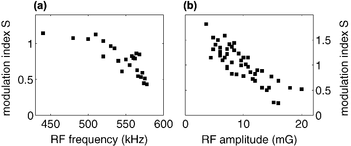
By exploiting the dependence of on the potential modulation (Eq.1 and 2) we control the population of the diffraction orders with the radio frequency field. The frequency and the amplitude of the oscillating field determines the coupling between internal atomic states and with it the depth and shape of the potential wells. Radio frequency control of diffraction (Fig.4) may be particulary convenient for integrated atom-optical devices when sequences of diffraction pulses are required. The phase modulation index can be electronically changed while the condensate performs a constant center of mass oscillation in the trap and interacts with the grating in subsequent oscillation periods.
The experimental results are derived from absorption images as illustrated in Fig.2. For the analysis, the images are summed up along the y-coordinate, perpendicular to the course of diffraction. The resulting line density profile is fitted first by the incoherent superposition of the diffraction orders, , to obtain the phase modulation index . Here, we assume that, at the time of absorption imaging, the centers of neighboring diffraction orders are separated by a distance of due to 8ms propagation in the trap followed by 20ms ballistic expansion Not (a). The repulsive atomic mean-field interaction is included by assuming the usual ballistic expansion of condensates Castin and Dum (1996). Thermal atoms are taken into account by a Gaussian contribution to the line density profile. The incoherent sum of diffraction orders fits well to the overall cloud envelope but it does not explain further details of the cloud.
Unlike diffraction from standard optical lattice potentials Hagley et al. (1999); Stenger et al. (1999); Kozuma et al. (1999); Simsarian et al. (2000); Bongs et al. (2001); Torii et al. (2000); Wang et al. (2005), the recoil energy transferred by the lattice is smaller than the chemical potential of the condensate. The diffraction orders do not separate entirely during ballistic expansion and the spatial distribution of the condensate is given by the coherent superposition of the diffraction orders Not (b): . We observe high contrast interference fringes of overlapping diffraction orders for phase modulation indices between (Fig.2). The fringes are dominated by the interference of the and orders with populations that are comparable in this range.
The phase of the individual diffraction orders after ballistic expansion results from evaluating the action integral Henkel et al. (1994). It contains various contributions: the parabolic phase profile characterized by a curvature Castin and Dum (1996), the center of mass momentum of the diffraction order given by Simsarian et al. (2000), and phase contributions and accumulated during propagation in the trap and during time of flight. Interference of overlapping diffraction orders results from the coherent superposition of the wavefunctions
We restrict our analysis to the reproducibility of the interference fringes for different realizations of the experiment. A reproducible spatial density distribution of atoms is a direct signature of phase coherent splitting and manipulation of the condensate Shin et al. (2004, 2005). The reproducibility of the interference fringes relies on the reproducibility of the spatial position of the condensate relative to the lattice. A variation of the position would show up as a variation of . Other phase contributions are set by the experimental conditions and do not change between successive realizations of the experiment. By fitting the data with the coherent superposition of the diffraction orders varying only the single parameter , we find that the relative phase of the diffraction orders is deterministic with an uncertainty of on average (standard deviation). A typical interference pattern is illustrated in (Fig.5a).
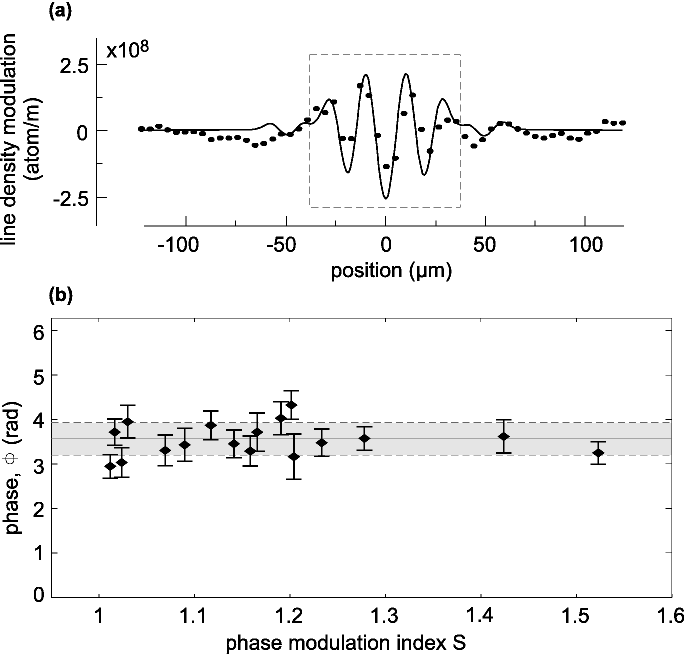
It shows the line density modulation of the cloud: . The phase , derived from the central part of the interference pattern, is plotted in Fig.5b. Taking into account the condensate’s axial size of () and the number of “illuminated” lattice sites () the observed phase spread is ”diffraction limited”, i.e. given by the resolution of the lattice . This uncertainty due to the finite size of the condensate could be further reduced by expanding the axial size of the cloud.
From the highly reproducible interference fringes we conclude that splitting of condensates with an integrated magnetic grating is phase coherent. In addition, we have proven that the experimental parameters can be controlled with an accuracy sufficient for the construction of integrated matter wave interferometers. In contrast to other schemes, the interferometer presented here requires a single diffraction event only. The interferometric path is closed by the ballistic expansion due to mean-field repulsion of the condensate atoms. For above experimental conditions, the resolution of a force detector is on the order of . The simultaneous interference of more than two diffraction orders allows not only for the detection of forces but also force gradients, and even higher spatial derivatives of external forces.
We thank C. J. Vale, T. Judd, and M. Fromhold for helpful comments on the manuscript. Financial support from the Landesstiftung Baden-Württemberg, and the European Union (MRTN-CT-2003-505032) is greatly acknowledged.
References
- Kasevich (2002) M. A. Kasevich, Science 298, 1363 (2002).
- Hagley et al. (1999) E. W. Hagley et al., Science 283, 1706 (1999).
- Stenger et al. (1999) J. Stenger et al., Phys. Rev. Lett. 82, 4569 (1999).
- Kozuma et al. (1999) M. Kozuma et al., Phys. Rev. Lett. 82, 871 (1999).
- Simsarian et al. (2000) J. E. Simsarian et al., Phys. Rev. Lett. 85, 2040 (2000).
- Bongs et al. (2001) K. Bongs et al., Phys. Rev. A 63, 031602(R) (2001).
- Torii et al. (2000) Y. Torii et al., Phys. Rev. A 61, 041602(R) (2000).
- Birkl and Fortágh (2007) G. Birkl and J. Fortágh, Las. Phot. Rev. 1, 12-23 (2007).
- Fortágh and Zimmermann (2007) J. Fortágh and C. Zimmermann, Rev. Mod. Phys. 79, 235 (2007).
- Wang et al. (2005) Y. Wang et al., Phys. Rev. Lett. 94, 090405 (2005).
- Günther et al. (2005a) A. Günther et al., Phys. Rev. Lett. 95, 170405 (2005a).
- Shin et al. (2005) Y. Shin et al., Phys. Rev. A 72, 021604(R) (2005).
- Schumm et al. (2005) T. Schumm et al., Nature Physics 1, 57 (2005).
- Jo et al. (2007) G.-B. Jo et al., Phys. Rev. Lett. 98, 030407 (2007).
- Günther et al. (2005b) A. Günther et al., Phys. Rev. A 71, 063619 (2005b).
- Sukumar and Brink (1997) C. V. Sukumar and D. M. Brink, Phys. Rev. A 56, 2451 (1997).
- Lesanovsky (2006) I. Lesanovsky et al., Phys. Rev. A 74, 033619 (2006), and references therein.
- Henkel et al. (1994) C. Henkel, J.-Y. Courtois, and A. Aspect, J. Phys. II France 4, 1955 (1994), and references therein.
- (19) T. E. Judd et al., in preparation.
- Not (a) After displacement, the cloud is held for 12ms in the trap. In the first 4ms the condensate reachs the magnetic lattice and is reflected. In the following 8ms the diffraction orders propagate in the axial potential of the trap.
- Castin and Dum (1996) Y. Castin and R. Dum, Phys. Rev. Lett. 77, 5315 (1996).
- Not (b) The thermal component does not contribute to the interference. Diffraction experiments with a thermal cloud just above the transition temperature for Bose-Einsten condensation do not show interference.
- Shin et al. (2004) Y. Shin et al., Phys. Rev. Lett. 92, 050405 (2004).