A Twisted Pair Cryogenic Filter
Abstract
In low temperature transport measurements, there is frequently a need to protect a device at cryogenic temperatures from thermal noise originating in warmer parts of the experiment. There are also a wide range of experiments, such as high precision transport measurements on low impedance devices, in which a twisted-pair wiring configuration is useful to eliminate magnetic pickup. Furthermore, with the rapid growth in complexity of cryogenic experiments, as in the field of quantum computing, there is a need for more filtered lines into a cryostat than are often available using the bulky low temperature filters in use today. We describe a low cost filter that provides the needed RF attenuation while allowing for tens of wires in a twisted pair configuration with an RF-tight connection to the sample holder. Our filter consists of manganin twisted pairs wrapped in copper tape with a light-tight connection to the shield of the sample holder. We demonstrate agreement of our filter with a theoretical model up to the noise floor of our measurement apparatus (90 dB). We describe operation of our filter in noise thermometry experiments down to 10 mK.
I Introduction
Nanoelectronic devices such as single electron transistors, quantum dots, and other quantum circuits are sensitive to thermal radiation from the portions of the experiment which are above the base temperature of the cryostat devoretJAP . Any thermal radiation that is not filtered can heat the electrons in the device being measured, defeating the purpose of cryogenic transport measurements. Furthermore, in some experiments, such as switching statistics measurements of Josephson junctions Martinisdevoretclarke , very small numbers of microwave photons can ruin the experiment. Thus, there is a need in cryogenic electronic experiments for filters that both provide thermalization to very low temperatures and have very high attenuation throughout a wide range of frequencies.
Filtering for single electron circuits is typically accomplished by use of a powder filter at the base temperature of the cryostat Martinisdevoretclarke , which consists of a copper tube packed with metal powder (either stainless steel or copper) into which approximately a meter of wire is coiled. Each end is typically fitted with a coaxial connector (e.g. SMA,) and the filters are connected using semi-rigid coaxial cables. A major drawback of this technique is that the space taken up per wire and the quantity of copper that must be cooled to base temperature (typically about 90 grams/wire) becomes prohibitive for large numbers of wires. Because these filters rely on SMA connectors and semi-rigid cables, there a limited number that can be practically installed in a given cryostat, and they must always be installed in a single-ended configuration. Under certain circumstances, it can be very advantageous to measure devices in a twisted pair configuration ott , and the single-ended SMA filters are not as compatible with that as a true twisted pair filter.
In addition to the standard powder filters, there exist a variety of other cryogenic filters devoretJAP ; courtois_RSI ; zorin_RSI ; kevin ; fukushima . While these are not all as intrinsically bulky as the powder filters, they all share the drawbacks of being built with coaxial connectors in a single-ended configuration. Furthermore, the photolithographically defined filters devoretJAP ; courtois_RSI add significant cost and complexity to the design.
We have constructed and tested a filter that can be easily hand-made from off-the-shelf components. Because the filter is in the form of a flexible cable, it can be bent to any desired shape and can easily fit in a cryostat wherever space is available. Unlike the filters that use SMA cables, our filter can be fitted with any one of a number of many-pin connectors and requires very little effort and an insignificant cost in space to increase the number of wires used in the design.
II Description of Filter
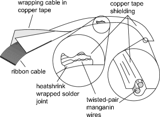
Our filter consists of a twisted pair of resistive wires wrapped tightly in copper tape. The copper tape acts both as a shield and as a ground to which the lines are capacitively coupled. The copper tape is pressed around the wires very closely so that the distance between the wires and the shield is that of the insulator thickness on the wires, about 10 microns. Thus there is a high capacitance from the wires to ground as well as between the two wires in any given pair. This capacitance to ground combined with the high resistivity of the wires makes the cable a continuous RC line (see figure 2). This system is simple enough that the RF loss of the line as a function of length can be fit to a simple model. This simplicity could prove useful when trying to model the time domain behavior of fast voltage pulses down the line.
The ends of the wires are soldered to a short segment of ribbon cable which allows for easy application of connectors and which is more mechanically and thermally robust than the main section of the cable (see figure 1.) The ribbon cable end may then be slotted through a copper shield into the box which contains the experiment, and sealed in with low temperature solder. This creates RF-tight continuous shielding from the noisy end of the filter down into the low noise shielded enclosure containing the experiment.
III Theory
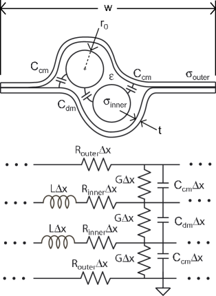
We can analyze the filter as a set of transmission lines with capacitance per unit length and for common mode and differential mode respectively, resistance per unit length R, and inductance per unit length L. Because of the finite skin depth of high frequency signals, R is frequency dependent. To analyze this line, we follow the standard treatment of the lossy transmission line pozar to find the complex propagation constant which corresponds to travelling wave solutions
can be computed from the DC conductivity and the fraction of the cross-sectional area that carries current at frequency . The skin depth is where is the permeability of the vacuum and is the DC conductivity of the material. We then compute the resistance of the inner and outer conductors at finite frequency as follows: , and .
To find the capacitances per unit length we both compute theoretical values and measure capacitances directly. The measurement of the capacitance is described below in the section on filter testing. The theoretical models are based on various published descriptions of transmission lines wadell .
Both the common mode and differential mode are treated using the simplified model shown in figure 3, with a single value for C calculated from the series and parallel combinations of and . We can compute C as follows:
| (1) |
The total resistance R used in the final calculation is then found from
| (2) |
The shunt conductance as a function of frequency is computed from the loss tangent as follows:
| (3) |
where is the loss tangent of the dielectric material.
The capacitance per unit length and the dielectric constant are fit parameters in the model, and the inductance is calculated from them using the assumption that . may be estimated from the value for the polyimide insulation on the wire.
The lumped-element inductance at each end of the line is from the wire that connects the inner conductor of the filter with the inner conductor of the 50 line from the network analyzer. This can be roughly estimated by assuming that the wire has about a nH per millimeter of inductance, and measuring the length of bare wire. Since there are about two or three centimeters of bare wire at each end, this gives a rough estimate of of about 30 nH. Not surprisingly, the best-fit inductance turns out to be a little higher, 45 nH.
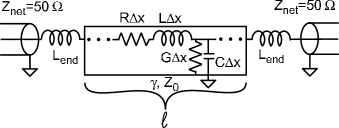
With the relevant parameters for the transmission line known, we can proceed to calculate the propagation constant as described above. From this we may use standard transmission line theory to calculate the insertion loss of the filter cable pozar :
| (4) |
where is the impedance of the line from the network analyzer in the test circuit (50 ), and is the impedance of the transmission line. For simplicity, we have shown the insertion loss of the filter cable alone. The actual theory we compare to network analyzer data includes the end inductances.
IV Assembly and Installation
The first step in fabrication of the cable is assembling the twisted pairs by fastening the pair at one end and twisting the opposite end with an electric drill motor until the pair is twisted at the desired pitch webtutorial . The inner conductor of our filter is polyimide-coated manganin wire 4 mils (100 microns) in diameter with a 0.25 mil (6 microns) thick insulating layer manganinwire . Once enough twisted pairs of the right length have been made, they must be arranged in the order in which they will be assembled into the cable and soldered to the ends of the ribbon cable. The solder joints are individually encased in heat shrink tubing to prevent shorting. The entire assembly of wires and ribbon cables is then wrapped up in copper tape coppertape by folding the tape twice as shown in figure 1. Once the tape is stuck to itself, form fitting adhesion to the wires may be achieved by pressing the whole assembly with a rolling pin. This gives the cable the profile shown in the cutaway blowup diagram in figure 1, maximizing the capacitance between the inner conductor and the shield.
The exposed ends of the cable are both ribbon cable, and are easily fitted with AMP modu solderless connectors. AMP sells a wide variety of connectors in the modu line including conversions to various other kinds of connectors and PC board pluggable connectors. This allows for easy connection to whatever connector one may have in the cryostat as well as to the PC board on which the sample is mounted.
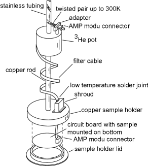
In order to make a light-tight connection from the shield of the cable to the sample holder, we use a copper “shroud” through which the cable is threaded which mates to the sample holder. This “shroud” consists of a copper box with a thin slot at one end and an open face surrounded by a flange at the other end (see figure 4.) The copper-shielded ribbon cable part of the cable is passed through the slot in the shroud which is then sealed with Indium-Cadmium low temperature solder (applied with a heat gun). This is done in such a way as to leave a little extra length in the cable so the AMP modu connector can be mated with the circuit board inside the sample holder. The shroud is then bolted over an opening in the sample holder and sealed with an Indium o-ring. When the whole system is assembled, there is light-tight shielding from the beginning of the cable all the way down to the sample holder, surrounding the sample.
V Testing of Filter
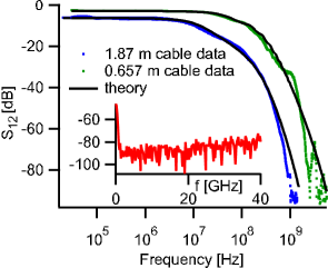
To test the filter, a test apparatus was constructed that consisted of a pair of SMA connectors whose center pins were soldered to a pair of wires. The SMA connectors were inset in a groove over which a brass plate was mounted, sealed with a pair of indium o-rings sandwiching the cable. This provided a light-tight seal from one pair of SMA connectors to the other. The transmission as a function of frequency was then measured on a HP8753D network analyzer from 30 kHz to 6 GHz, and from 50 MHz to 40 GHz on a HP8722D network analyzer. Figure 5 shows a plot of at room temperature compared with theoretical transmission for two different lengths of cable. Note that the behavior of the filters is monotonic and very close to the predicted behavior.
By adjusting the parameters slightly, good fits can be found with very reasonable values for all the parameters. The values of the parameters are in Table 1.
| Parameter | Value | Units |
|---|---|---|
| pF/m | ||
| nH/m | ||
| m | ||
| m | ||
| nH |
Note that is approximately the value of the relative dielectric constant for polyimide. In this model, all of the parameters we use are physically reasonable, which may be contrasted to the powder filter, in which it is difficult to construct such a model.
The capacitance per unit length was measured by connecting a 10 k resistor in parallel with the cable to a EGG 5113 low noise pre-amp in front of a Stanford Research Systems SR760 FFT analyzer. Looking at the RC rolloff of the noise spectrum, it was possible to determine the capacitance per unit length. By connecting the 10 k resistor either between the two conductors of a twisted pair or from one conductor to the shield it was possible to separately measure the common mode and differential mode capacitance.
By neglecting the resistance of the manganin wire and treating the whole cable as just a capacitor, the Johnson noise spectrum can be measured and fit to extract the desired capacitances. In order to eliminate the extra capacitance from the connectors at the end of the cable, we measure different cable lengths and estimate the capacitance per unit length by computing . This yielded capacitance values of Ccm=200 pF/m and Cdm=51 pF/m.
The capacitances can also be estimated to check how reasonable our values are by computing certain theoretical limits. In one limit, we consider the line to be a coaxial line with the insulation on the wire surrounded tightly by copper. In the opposite limit, we consider the wire to be sandwiched halfway between a pair of ground planes pushed up against the outside of the insulation. In the first limit, the capacitance is given by
| (5) |
where is the relative dielectric constant, r is the radius of the wire (50 microns), and s is the thickness of the insulation (6.4 microns.) In the second limit, the capacitance of the so-called “slabline” wadell can be calculated as
| (6) |
where we assume that the average relative dielectric constant is 1. As expected, the actual capacitance, 210 pF/m, is between these limits.
Having installed the cable in the cryostat, we have tested it by measuring superconducting tunnel junctions and single electron transistors. By observing the single electron transistor current-voltage characteristics, we can evaluate the cable’s filtering capability. So far we have used this cable in our Heliox pumped 3He cryostat and our dilution refrigerator with great success for both tunnel junction experiments and single electron transistor experiments. In addition, we test the thermalization of the electrons at low temperatures by measuring the noise of a tunnel junction as a function of bias voltage, i.e. by doing a shot noise thermometer measurement spietzscience . We used this method to verify that the electron temperature of our sample was as low as 10 mK SNT_lowtemp . In all samples tested, the device physics observed was consistent with an electron temperature equal to the physical temperature of the cryostat.
Acknowledgements.
We thank Michel Devoret for useful discussions, and the David and Lucile Packard Foundation for support.References
- (1) D. Vion, P. F. Orfila, P. Joyez, D. Esteve, and M. H. Devoret, J. Appl. Phys, 77, 2519 (1995).
- (2) J. M. Martinis, M. H. Devoret, and J. Clarke, Phys. Rev. B, 35, 4682 (1987).
- (3) D. C. Glattli, P. Jacques, A. Kumar, P. Pari, and L. Saminadayar, J. Appl. Phys, 81, 7350 (1997).
- (4) J. M. Hergenrother et al., Phys. Rev. B Rapid Communications, 51, 9407 (1995).
- (5) H. Courtois, O. Buisson, J. Chaussy, and B. Pannetier, Rev. Sci. Instrum., 66, 3465 (1995).
- (6) A. B. Zorin, Rev. Sci Instrum., 66, 4296 (1995).
- (7) Pozar, D. M., Microwave Engineering, 2nd Ed. Wiley, New York, (1998).
- (8) A graphical tutorial on construction of the filter can be found at http://www.eng.yale.edu/rslab/cryogenic_filter.htm.
- (9) 38 Gauge single build polyimide coated manganin wire from MWS Wire Industries, http://www.mwswire.com.
- (10) 3M tape #1181, 1” or 1.5” wide, available from Allied Electronics, Allied stock number 617-4710, http://www.alliedelec.com. Note that there are other types of copper tape available that are not suitable because there is a layer of paper between the copper and the adhesive.
- (11) H. Ott, Noise Reduction Techniques in Electronic Systems, 2nd Ed. (Wiley, New York, 1988)
- (12) K. Bladh et al., Rev. Sci. Instrum, 74, 1323 (2003).
- (13) Akio Fukushima et al., IEEE Trans. on Instrumentation and Measurement, 46, No. 2, 289 (1997).
- (14) M.J. Roberts, Rev. Sci. Instrum,
- (15) Wadell, B. C., Transmission Line Design Handbook, Artech House, Norwood, MA, (1991).
- (16) Lafe Spietz, K. W. Lehnert, I. Siddiqi, R. J. Schoelkopf, Science, 300, 1929 (2003).
- (17) Lafe Spietz, R. J. Schoelkopf, in preparation.