Address: ]Institute of Physics, St.Petersburg State University, Ulyanovskaya 1, Petrodvorets, 198504 St. Petersburg, Russia
Observation of Spin Relaxation Anisotropy in Semiconductor Quantum Wells
Abstract
Spin relaxation of two-dimensional electrons in asymmetrical (001) AlGaAs quantum wells are measured by means of Hanle effect. Three different spin relaxation times for spins oriented along [110], and [001] crystallographic directions are extracted demonstrating anisotropy of D’yakonov-Perel’ spin relaxation mechanism. The relative strengths of Rashba and Dresselhaus terms describing the spin-orbit coupling in semiconductor quantum well structures. It is shown that the Rashba spin-orbit splitting is about four times stronger than the Dresselhaus splitting in the studied structure.
pacs:
73.21.Fg, 73.63.Hs, 72.25.Rb, 76.60.JxSpintronics is at present time one of the most important areas of the semiconductor physics for both fundamental research and possible device applications spintronicbook02 . The main problem of spintronics is creation, registration and lifetime control of carrier spin, especially in low-dimensional systems. Therefore investigation of spin relaxation processes is now an actual problem of the physics of semiconductor heterostructures.
The main mechanism of spin relaxation in GaAs based quantum wells (QWs) is the D’yakonov-Perel’ kinetic mechanism Dyakonov86p110 . It is caused by lack of inversion centrum i) in the bulk semiconductor of which the system is made (bulk inversion asymmetry, or BIA), ii) in the heterostructure (structure inversion asymmetry, or SIA) and iii) in the chemical bonds at heterointerfaces (interface inversion asymmetry, or IIA) Dyakonov86p110 ; Bychkov84p78 ; Roessler02p313 . SIA can be caused by an external electric field or by deformation, BIA and IIA depend strongly on a size of carrier confinement. Therefore spin relaxation times can be controlled by gate voltage or by special heterostructure design.
In Ref. Averkiev1999p15582 , anisotropy of spin relaxation has been predicted for heterostructures grown along the axis [001]. It has been theoretically shown that lifetimes of spin oriented along the axes [110], and [001] are different. In particular, changing relation between SIA and BIA one can achieve total suppression of relaxation for spin oriented along one of axes. (IIA in (001)-grown structures is equivalent to BIA, therefore we will use a generalized term ‘BIA’ for both of them.) Detailed calculations Averkiev02pR271 ; FTP ; Kainz03p075322 confirmed that spin relaxation anisotropy exists in real semiconductor heterostructures. Realization of such idea to control spin relaxation times gives new opportunities for spintronics Schliemann03p146801 . However experimental discovery of this effect is missed so far.
In this Letter, spin relaxation anisotropy in the plane of the QW is observed. In order to demonstrate this effect, the structure has been grown so that SIA and BIA are comparable in efficiency. Note that systems where both SIA and BIA take place have been studied in Refs. PikusPikus ; Jusserand95p4707 ; Miller03p076807 ; BIASIA but spin relaxation times have not been investigated in such structures.
The D’yakonov-Perel’ spin relaxation mechanism consists in electron spin precession around an effective magnetic field which is caused by lack of inversion centrum in the system. The corresponding Hamiltonian of spin-orbit interaction has the form
| (1) |
where is a vector of Pauli matrices and is a precession frequency dependent on the electron quasimomentum .
The direction of the precession axis is determined by the carrier momentum and by kind of inversion asymmetry. SIA generates the effective field oriented perpendicular to . BIA results in the field which direction depends on the angle between the momentum and crystallographic axes. In (001) QWs both SIA and BIA produce effective magnetic fields lying in the plane of the structure. In the coordinate system , the precession frequences have the form
| (2) |
If only one kind of inversion asymmetry is present, e.g. SIA, then the precession frequency is the same for all momentum directions: , Eq.(2). As a result, spin relaxation times do not depend on spin orientation in the structure plane Dyakonov86p110 .
If the system has both kinds of inversion asymmetry then the effective magnetic field is a vector sum of the corresponding SIA and BIA terms: . In this case the precession frequency depends on the momentum direction of carriers Silva92 :
where is an angle between and the axis . The angular dependence is presented in Fig. 1. Due to anisotropy of in the -space, the spin relaxation rate depends on the spin orientation relative to crystallographic axes Averkiev1999p15582 ; Averkiev02pR271 . In particular, if SIA and BIA strengths are identical (), then the effective magnetic field is oriented along the same axis for all directions of electron momentum. Therefore the spin oriented along this direction (one of axes) does not relax at all. Two other spin components disappear with finite rate. This means giant spin relaxation anisotropy.

Spin relaxation times are given by the following expressions Averkiev1999p15582
| (3) |
for spin oriented along the growth axis, and
| (4) |
for spins oriented along and [110] axes. Here is a factor determined by temperature and momentum relaxation time independent of spin-orbit interaction parameters.
In Eqs. (2)-(4) we neglect -cubic terms in . Since typical electron kinetic energy at liquid nitrogen temperature relevant in the experiment is much less than the energy of size quantization, the role of these terms in spin relaxation is inessential Averkiev02pR271 ; FTP .
The spin relaxation times can be measured in time-resolved or steady-state photoluminescence (PL) experiments. In the present work, we used the method of PL depolarization by transverse magnetic field (Hanle effect). The Hanle linewidth is determined by a lifetime of spin oriented perpendicular to the magnetic field . Therefore measuring PL circular polarization degree in the geometries and , one can extract the times and .
The degree of circular polarization of radiation in these two geometries has a Lorentzian form
Here the halfwidths are given by
| (5) |
where is an electron factor Landé in the QW plane, and is the Bohr magneton. We suppose that spin relaxation is much faster than radiation recombination: (; is the radiative recombination time). In this model, under recombination of electrons with heavy holes in the ground state, .
From Eq. (4), (5) follows the expression for spin splittings
| (6) |
One can see that, even for dominance of one splitting over another (e.g. ), spin relaxation anisotropy can be registered experimentally because halfwidths of the Hanle curves differ two times stronger than the spin splittings: .
If one knows the -factor and the Hanle contour halfwidths , one can determine the products and . For the D’yakonov-Perel’ mechanism, the spin relaxation rates obey the following relation
- cf. Eqs. (3), (4). This allows one to determine all three spin relaxation times from the Hanle effect measurements.
In order to observe the expected effect an asymmetrical QW was prepared. The sample was grown by molecular beam epitaxy method on a semi-insulating GaAs substrate along the [100] direction and contained a 200 nm Al0.28Ga0.72As barrier layer, a 80 Å GaAs QW, the other sloping barrier grown with content of Al changing from 4 to 28 % on the length of 270 Å, and the barrier layer of width 200 nm. A sketch of the studied structure is shown in the inset of Fig. 2. In order to avoid oxidation of the structure there was grown a 3 nm GaAs cap layer. Al concentration has been varied by change of the source temperature. The growth temperature was 600∘ C. The sample was nominally undoped.
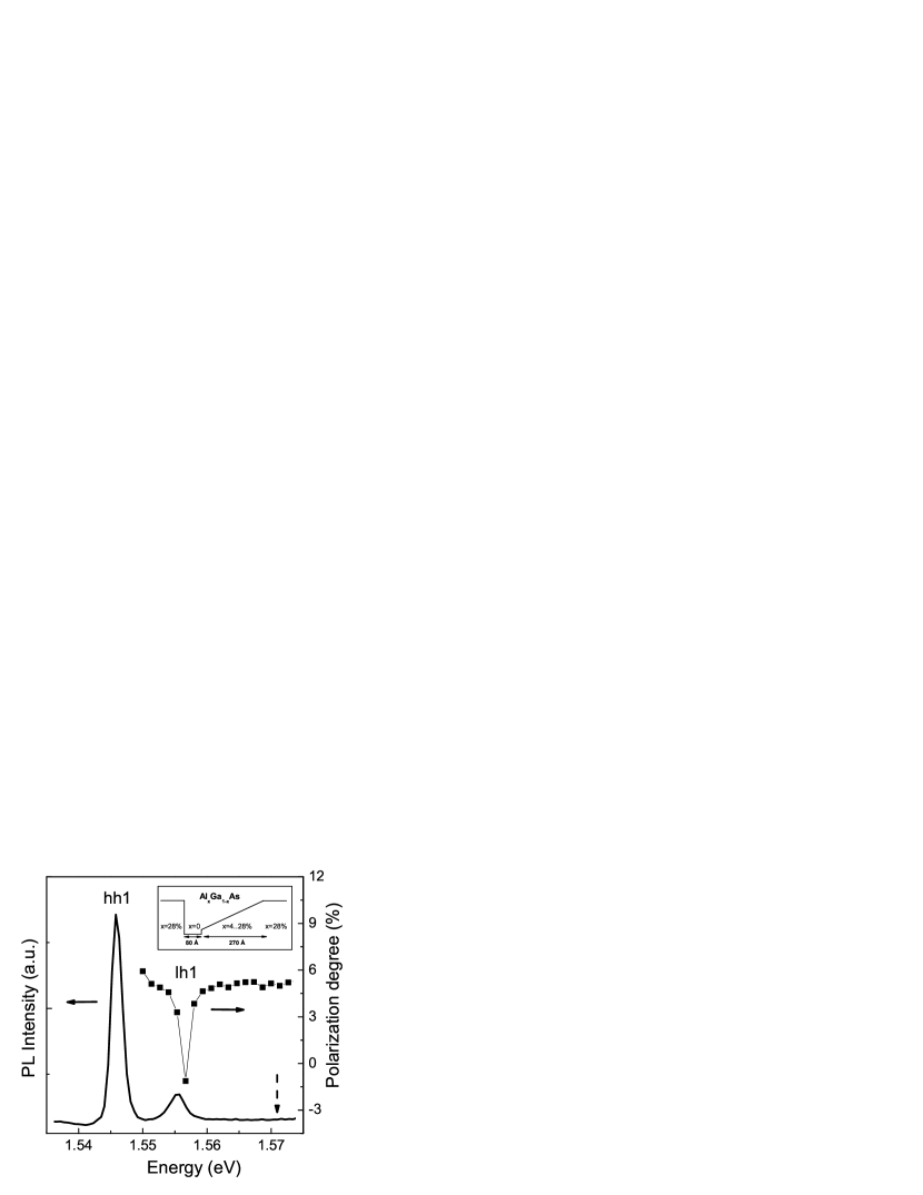
For PL excitation we used a Ti:Sa laser pumped by???? an Ar-ion laser. This allowed us to realize quasi-resonant excitation of QW states. The sample was placed into a glass cryostat and was immersed into liquid nitrogen. The cryostat was placed into an electromagnet creating a dc magnetic field up to 0.75 T directed perpendicular to the excitation axis (Voigt geometry). In Fig. 2 PL spectrum of the asymmetrical QW GaAs/AlGaAs at temperature K is shown. The spectrum has two lines caused by recombination of electrons with ground states of heavy holes (hh1) and light holes (lh1). The same figure presents an excitation spectrum of optical orientation signal under registration in the main maximum of PL (hh1). Far from PL spectrum resonances, the signal weakly depends on the excitation energy being at the level of 5.5 %. At the resonance, the optical orientation signal drops sharply and became negative. This implies that the resonance is caused by recombination of electrons with the lh1 states.
In Fig. 3 experimental Hanle curves are presented for two orientations of a magnetic field. Open circles and closed squares correspond to magnetic field directed along the axes [110] and . One can see that optical orientation is almost totally suppressed in the field 0.3 T, however widths of two curves differ significantly. Solid lines in Fig. 3 represent fitting of the Hanle curves by the Lorentz function. Obtained fitting parameters and for two orientations of the field are 0.12 T and 0.075 T. This means that Hanle linewidth anisotropy is around 60 %.
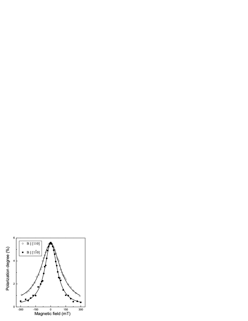
Since %, the spin relaxation times are much shorter than the radiative recombination time . This allows us to use Eq. (5) in the analysis, where are determined solely by the spin relaxation times. Therefore the Hanle contour halfwidths for two field orientations yield the spin relaxation times and the ratio , i.e. relative strengths of the Rashba and Dresselhaus splittings in the studied structure - cf. Eq.(6).
In the analysis we neglect anisotropy of the -factor in the QW plane because even if observed it does not exceed 10 % g_aniz . Despite of this anisotropy also originates from -linear terms in the Hamiltonian (1), its magnitude is small due to smallness of the spin splitting KK . Therefore it can be important only if the isotropic part of the -factor is close to zero. In the AlGaAs heterostructures under study, ivch_book , i.e. sufficiently differs from zero, therefore its anisotropy is inessential.
Note that both [110] and directions belong to the same family of crystallographic axes. Therefore, strongly speaking, one can determine either or the reciprocal value from Hanle effect measurements. However the Rashba splitting is usually larger than the Dresselhaus splitting in [001] GaAs QWs. Therefore we believe that the value given above corresponds namely to , i.e. the Rashba splitting is about four times larger than the Dresselhaus splitting in the studied structure. This value of agrees well with data on III-V QWs Jusserand95p4707 ; Miller03p076807 ; BIASIA .
To summarize, electron spin relaxation anisotropy is observed in the [001] grown QW. The anisotropy is measured by dependence of the Hanle linewidth on magnetic field orientation in the QW plane. It is demonstrated that the Rashba effect dominates the Dresselhaus effect in the studied structure. Spin relaxation times of electrons in the [001] QWs at liquid nitrogen temperature are determined for all three spin orientations.
Financial support from RFBR and INTAS is gratefully acknowledged. Work of L.E.G. is also sponsored by “Dynasty” Foundation — ICFPM and by Russian President grant for young scientists.
References
- (1) Semiconductor Spintronics and Quantum Computation, edited by D.D. Awschalom, D. Loss, and N. Samarth, Nanoscience and Technology (Springer, Berlin, 2002).
- (2) M.I. D’yakonov, and V.Yu. Kachorovskii, Fiz. Tekh. Poluprov. 20, 178 (1986) [Sov. Phys. Semicond. 20, 110 (1986)].
- (3) Y.A. Bychkov, and E.I. Rashba, Pis’ma Zh. E’ksp. Teor. Fiz. 39, 66 (1984) [JETP Lett. 39, 78 (1984)].
- (4) U. Rössler and J. Kainz, Solid State Commun. 121, 313 (2002).
- (5) N.S. Averkiev and L.E. Golub, Phys. Rev. B 60, 15582 (1999).
- (6) N.S. Averkiev, L.E. Golub and M. Willander, J. Phys.: Condens. Matter 14, R271 (2002).
- (7) N. S. Averkiev, L. E. Golub, and M. Willander, Fiz. Tekh. Poluprov. 36, 97 (2002) [Semiconductors 36, 91 (2002)].
- (8) J. Kainz, U. Rössler, and R. Winkler Phys. Rev. B 68, 075322 (2003).
- (9) J. Schliemann, J.C. Egues, and D. Loss, Phys. Rev. Lett. 90, 146801 (2003).
- (10) F.G. Pikus and G.E. Pikus, Phys. Rev. B 51, 16 928 (1995).
- (11) B. Jusserand, D. Richards, G. Allan, C. Priester, and B. Etienne, Phys. Rev. B 51, 4707 (1995).
- (12) J.B. Miller, D.M. Zumbühl, C.M. Marcus, Y.B. Lyanda-Geller, D. Goldhaber-Gordon, K. Campman, and A.C. Gossard, Phys. Rev. Lett. 90, 076807 (2003).
- (13) S.D. Ganichev, V.V. Bel’kov, L.E. Golub, E.L. Ivchenko, P. Schneider, S. Giglberger, J. Eroms, J. De Boeck, G. Borghs, W. Wegscheider, D. Weiss, and W. Prettl, Phys. Rev. Lett. 92, 256601 (2004).
- (14) E. A. de Andrada e Silva, Phys. Rev. B46, 1921 (1992).
- (15) S. Hallstein, M. Oestreich, W.W. Rühle and K. Köhler, in High Magnetic Fields in the Physics of Semiconductors II, edited by G. Landwehr and W. Ossau (World Scientific, 1997), Vol 2, p. 593.
- (16) V.K. Kalevich and V.L. Korenev, Pis’ma Zh. E’ksp. Teor. Fiz. 57, 557 (1993) [JETP Lett. 57, 571 (1993)].
- (17) Optical Spectroscopy of Semiconductor Nanostructures, E.L. Ivchenko (Alpha Science Int., Harrow, U.K., 2005).