Phase signal definition for electromagnetic waves in X-ray crystallography
Abstract
Diffracted X-ray waves in crystals have relative phases regarding the mathematical format used to describe them. A forward propagating wave can be defined with either negative or positive time evolution, i.e. or . Physically measurable quantities are invariant with respect to the choice of definition. This fact has not been clearly emphasized neither extensively explored when deriving well-established equations currently being used in many X-ray diffraction related techniques. Here, the most important equations are generalized and consequences of conflicting undertaken definitions discussed.
I Introduction
Electromagnetic waves are in general described by an expression such as
| (1) |
where stands for the global phase signal definition of monochromatic forward propagating waves. Both choices of phase signal ( or ) are allowed and both can be founded in several theoretical approaches of the X-ray diffraction phenomenon in crystals.
Physically measurable quantities are invariant regarding two distinct and independent choices: one is the choice on how to describe the forward propagating X-ray wave, represented here by the options and ; and the other is the choice of origin for the spatial position . In the literature of X-ray diffraction (see for instance Refs. inte2001, ; auth2001, ; ashc1976, ; kitt1996, ; jens2001, ) these two distinct choices have been of particular relevance for deriving important mathematical expressions, such as those of the structure factor of a crystal unit cell and of the atomic form factor. Whatever is the chosen option, , it can be compensated by the choice of origin so that the expressions are obtained in their standardized format without showing any dependence to the phase signal option.
This standard procedure links the choice of origin to the choice of phase signal, which is unreal since both choices are independent from each other. The real fact is that the available expressions are in agreement with only one value of for each given choice of origin. Consequently, the propagating waves in the medium must be described according to the implicitly undertaken choices, otherwise measurable features such as the positioning of standing wavefields —formed inside crystals undergoing diffraction— as well as invariant phase values —accessible via -beam diffraction experiments hart1961 — will be affected by conflicting definition of the global phase signal.
In this work the conflicting points are demonstrated and commonly used expressions in X-ray crystallography are generalized for any preference of signal choice . Signal shifts owing to geometrical factors are avoided by choosing the origin further way from the diffracting volume. The consequences only on the choice of is then exploited and discussed in the rest of the paper. Moreover, to facilitate part of the demonstration, an adaptation of the Stokes relations for Bragg reflection in perfect low-absorbing crystals is presented.
II Susceptibilities to phase signal definition
II.1 Structure factor
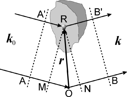
As depicted in Fig. 1, the scattered wave
towards direction depends on the relative phase between the rays from the origin and from the electron density at any given position , as for instance at . In the wavefront ,
and
Since the origin has been chosen outside the electron density distribution , there is no scattering at the origin, i.e. . Also, the origin was chosen in a such way to guarantee that to all positions inside the volume where , hence
and
| (2) | |||||
The choice-of-origin phase , is common to all elements of volume at any instant of time, and can be conveniently chosen to provide . If ( is the scattering amplitude of a single electron), the total scattered wave by the volume V is
| (3) |
In X-ray crystallography, the structure factor corresponds to the total scattered wave from an unit cell, which is ( is the unit cell volume). Therefore, it follows from Eq. (3) that
| (4) |
where , is the diffraction vector of reflection H, and is the atomic form factor inte2001 of the atom at the position in the unit cell.
II.2 Electron density of the unit cell
The step from Eq. (3) to Eq. (4) is better comprehended when written the electron density of the unit cell
| (5) |
in terms of Dirac -functions
| (6) |
The sum in stands for three sum on integer numbers , and , running from to since and , and are the fractional coordinates of the atoms in the unit cell. is in fact the Müller index of a given reflection H.
The option in the exponent of Eq. (6) is not related to the choice but it can be conveniently used to obtain
| (7) |
Methods for experimental determination of , or structure determination methods, are based on the above expression Eq. (7), although it has been standardized for the choice.
II.3 Standing waves
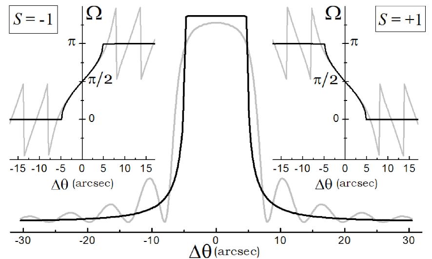
The X-ray reflection coefficient of a crystal with planes (crystal thickness , lattice period ) in symmetric Bragg reflection geometry can be written as
| (8) |
where is the rocking curve angle, i.e. the angle between the incident X-ray wave and the lattice planes. is the phase of the structure factor in Eq. (4), and is known as the dynamical phase auth2001 varying from the value at the left shoulder of the diffraction peak to the value at the right shoulder; both values will be given latter on.
To calculate the positioning of the standing waves during the rocking curve, the incident and reflected waves at a given depth are approximated to
| (9) |
and
| (10) |
where and are their oscillation directions. A comparable reflection coefficient at all depths is assumed, i.e. do not depend on . All dependence with depth is accounted for , which is a smooth function with very small variation over the lattice period.
The standing wavefield is therefore whose time-average intensity at any depth is proportional to
| (11) |
providing antinodes (maxima of intensity) at
| (12) |
for every integer value of .
For sake of simplicity, a single atomic layer per lattice plane period is assumed so that ,
and where gives the atomic layer position in the crystal unit cell. If , the unit cell origin would fall on top of the atomic layer.
From Eq. (12) we have the antinodes at
| (13) |
as a function of the dynamical phase , and
| (14) |
as the displacement of the antinodes during the crystal’s rocking curve. Such displacement must be invariant regarding the choice of signal and, therefore, it can be assumed that
It is widely known from dynamical diffraction theory auth2001 that and . However, a clear statement should be made to emphasize that this phase variation is relative to the global phase signal , as demonstrated below.
II.4 Dynamical phase shift versus global phase signal
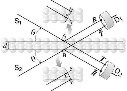
Coherent scattering and transmission of electromagnetic waves by very thin and uniform planes of low-absorbing matter are describable by reflection, and , and transmission, and , coefficients as depicted in Fig. 2. The condition
| (16) |
is required by energy conservation, which stipulates phase relationships between the reflected and transmitted waves, as usually obtained for laser beam splitters loud2000 or, equivalently, by the Stokes relations for time reversibility of wave’s propagation knit1976 .
Without loosing generality, these coefficients can be written as
| (17) |
in order to fulfill Eq. (16). and are the amount by which the phases of the reflected waves can differ from the phases of the transmitted ones, and and are the phase delays across the plane, whose thickness is comparable to the wavelength .
To determine the phase delays consider first only the source in Fig. 2. As shown in the top inset, if is the incident wave at point , is the transmitted wave at point passing through point . Then,
where since and stand for positions on the same wavefront , providing
Since the incidence angle is the same for both sources and, consequently,
| (18) |
The X-ray reflectivity of a crystal, as given in Eq. (8), is obtained by stacking lattice planes whose reflection and transmission coefficients are written in the same format used above, Eq. (17). Stacking in geometrical progression of planes () is the fastest way to go from a single lattice plane to the desired thickness . It is possible by means of the recursive equation
| (19a) | |||
| and | |||
| (19b) | |||
whose derivation is very similar to the Airy’s formula of the Fabry-Perot interferometer, and where
| (20a) | |||
| and | |||
| (20b) | |||
, , Å (classical electron radius), and stands for photoabsorption probability on each individual lattice plane, as discussed in details and compared to other diffraction theories elsewhere more2005 .
III Discussion on phase invariants
Phase determination is a fundamental problem in X-ray crystallography. Reflection intensities only provide as experimental data input for in Eq. (7). Then, what phase should be assigned to the structure factor of each crystal reflection?
For decades, great effort has been dedicated in developing and improving methods to estimate reflection phases, but since these are relative choice-of-origin values, the estimable quantities are in fact the differences among reflection phases, better known as phase invariants giac1999 . For instance, consider three reflections , and whose diffraction vectors fulfill the condition . Hence, in the structure factor ratio
the triple phase is invariant regarding the choice of origin in Fig. 1.
Three-beam diffraction experiments hart1961 ; shen1987 ; more2002 ; more2005b are sensitive to . In azimuthal scan mode, the diffracted intensity of reflection is modulated by the excitation of the reflection during the crystal rotation around . This intensity modulation is approximately given by
| (21) |
which explicitly depends on the dynamical phase of the reflection . and stand for the diffracted wavefields from reflection , kept constant during the -scan, and from the detour reflection .
Although the signal of changes with , the invariance of is assured by the cosine, an even function. However, both angles must stand for the same choice of in Eqs. (4) and (18). Otherwise, the experimental determination of by -scan data analysis would be compromised.
Besides the signal of , its modulus will also change with when the and corrections inte2001 of the atomic form factor —the so-called anomalous scattering corrections— are taken into account. According to the structure factor expression in Eq. (4)
| (22) |
and then and when . It is unacceptable since these inequalities would imply in different diffracted beam intensities for each possible choice of wave representation, or . To avoid such artificial fact, the correction must bear its depence with , so that
| (23) |
IV Conclusions
Structure factor, dynamical phase shift, phase invariants, and complex atomic form factor are values susceptible to the choice of global phase signal, as explicitly demonstrated here. When a measurable quantity depends on more than one of these values, they must be calculated for the same choice of phase signal.
Recursive equations based on Stokes relations are applied for calculating the reflectivity of low-absorbing crystals with a finite number of lattice planes. These recursive equations are extremely simple and, yet, capable of describing important features of the diffraction phenomenon such as kinematical diffraction (thin crystals), primary extinction (maximum reflectivity equal to 1), intrinsic width of Bragg reflections in either kinematical or dynamical diffraction regimes, and the phase shift of the diffracted waves across the reflection domain.
Acknowledgements.
The author would like to thank Prof. Paulo A. Nussenzveig for valuable discussions and very kind revision of the manuscript, as well as the Brazilian founding agencies FAPESP, grant number 02/10387-5, and CNPq, proc. number 301617/95-3.References
- (1) International Tables for Crystallography Vol. B, 2nd. edition (2001).
- (2) A. Authier, Dynamical Theory of X-ray Diffraction, 2nd ed. Oxford University Press (2001).
- (3) N.W. Ashcroft and N.D. Mermin, Solid State Physics, Saunders (1976).
- (4) C. Kittel, Introduction to Solid State Physics, 7th ed. Wiley & Sons (1996).
- (5) J. Als-Nielsen and D. McMorrow, Elements of Modern X-ray Physics, Wiley & Sons (2001).
- (6) M. Hart and A.R. Lang, “Direct determination of X-ray reflection phase relationships through simultaneous reflection”
- (7) S.L. Morelhão and L.H. Avanci, “On diffraction and absorption of X-rays in perfect crystals”, http://arxiv.org/abs/cond-mat/0505398 (2005).
- (8) P. Trucano, “Use of dynamical diffraction effects on x-ray fluorescence to determine the polarity of GaP single crystals” Phys. Rev. B 13, 2524-2531 (1984).
- (9) M.J. Bedzyk, G. Materlik and M.V. Kovalchuck, “X-ray-standing-wavemodulated electron emission near absorption edges in centrosymmetric and noncentrosymmetric crystals” Phys. Rev. B 30, 2453-2461 (1984).
- (10) R. Loudon, The Quantum Theory of Light. 3rd ed. Oxford University Press (2000).
- (11) Z. Knittl, Optics of Thin films. New York: Wiley (1976).
- (12) C. Giacovazzo, Direct phasing in crystallography. IUCr/Oxford Science publications (1999). Phys. Rev. Lett. 7, 120 (1961).
- (13) Q. Shen and R. Colella, “Solution of phase problem for crystallography at a wavelength of 3.5Å ” Nature (London) 329, 232 (1987)
- (14) S.L. Morelhão and S. Kycia, “Enhanced X-ray phase determination by three-beam difraction” Phys. Rev. Lett. 89, 015501 (2002).
- (15) S.L. Morelhão, L.H. Avanci and S. Kycia, “Study of crystalline structures via physical determination of triplet phase invariants” Nucl. Intrum. Meth. B 238, 175-184 (2005).