Flow of foam past an elliptical obstacle
Abstract
To investigate the link between discrete, small-scale and continuous, large scale mechanical properties of a foam, we observe its two-dimensional flow in a channel, around an elliptical obstacle. We measure the drag, lift and torque acting on the ellipse versus the angle between its major axis and the flow direction. The drag increases with the spanwise dimension, in marked contrast with a square obstacle. The lift passes through a smooth extremum at an angle close to, but smaller than 45∘. The torque peaks at a significantly smaller angle, 26∘. No existing model can reproduce the observed viscous, elastic, plastic behavior. We propose a microscopic visco-elasto-plastic model which agrees qualitatively with the data.
pacs:
82.70.Rr, 83.80.Iz, 47.50.-dA foam is a model to study materials which are viscous, elastic, and plastic. This complex, ubiquitous behavior is exploited in numerous applications, such as ore separation, drilling and extraction of oil, food or cosmetic industry Weaire1999 , but is not yet fully understood Hohler2005 . Foam rheology is thus an active research area, and recent studies provide insight to understand the interplay between the bubble scale and the whole foam behavior Denkov2005 ; Cantat2005 and to unify elasticity, plasticity and viscosity Weaire . Here, we study the flow of foam around an ellipse, where the measured lift, drag and torque show the whole complexity of foam rheology, which strongly constrains possible models: simple ones do not capture the observed features. We propose an elastoplastic model which describes well the data. We discuss the generality, implications and limitations of this model.
We have built a foam channel Dollet2005 to investigate a 2D steady flow and measure the force it exerts on an obstacle (Stokes experiment Dollet2005 ; Courty2003 ; deBruyn2004 ; Alonso2000 ; Cantat2005b ). Briefly, a 1 m long, 10 cm wide tank is filled with deionized water with 1% of commercial dish-washing liquid (Taci, Henkel). Its surface tension is mN m-1, and its kinematic viscosity is mm s-2. Several computer controlled injectors blow nitrogen in the solution to form a horizontal monolayer of bubbles of average thickness mm, confined between the bulk solution and a glass top plate (quasi-2D foam) Cox2003 . This foam is monodisperse (bubble area at channel entrance: mm2) and its fluid fraction is estimated to be around 7% Raufaste .
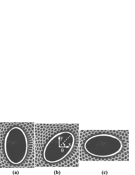
We study here the simplest shape which symmetry is low enough to observe simultaneously drag, lift and torque: the ellipse (Fig. 1). The obstacle has a major axis mm and minor axis mm. It floats freely just below the top glass surface, without solid friction. The upper end of an elastic fiber passes through a hole in the bottom of the obstacle, ensuring its free rotation, while its lower end is fixed, so that a top view of the obstacle displacement from its position at rest measures, with a precision better than 0.1 mN, the force exerted by the foam on the obstacle.
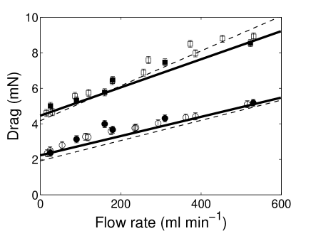
We measure the drag in the parallel orientation (), which is stable (see below); and in the perpendicular one (), which is unstable (but where the ellipse can remain for one hour, enough to perform steady flow measurements). The results (Fig. 2) are very close to that for circles of diameters 30 and 48 mm, respectively: this suggests (see also Fig. 4a) that drag is proportional to the spanwise direction (along the axis) of the ellipse:
| (1) |
In a steady flow (530 ml min-1, i.e. a velocity of 2.5 cm s-1), we start from a given initial orientation (76, 64, 48 or 18∘), let the ellipse rotate freely to its parallel stable orientation, and measure the angle, drag and lift (Fig. 3). The angular velocity strongly increases in the range (with a peak at 26∘) and does not depend on the initial orientation (insert of Fig. 3). Moreover, the forces correlate to ; we thus eliminate the time and plot the dependence of drag and lift with (Fig. 4a). All the forces data collapse on two master curves, one for the drag and one for the lift. The drag increases roughly linearly with except very close to 0∘ and 90∘, where it is extremal by symmetry (it equals 4.5 mN for 0∘ and 8.8 mN for 90∘). As suggested before, the experimental angular dependence of the drag is close to the one of the spanwise dimension, despite small discrepancies for angles close to 0∘ and 90∘. The lift vanishes at 0∘ and 90∘, as expected by symmetry; it is negative (downwards) for angles between 0∘ and 90∘, with a maximal value of 3 mN at an angle of about 40∘.
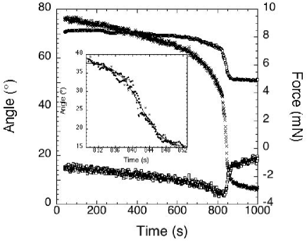
These measurements are independent of the initial orientation, even in the region of quickest variation (insert of Fig. 3). This suggests that the results, obtained in transient regimes, would be the same if we could fix to perform steady flow measurements. In fact, at a lower flow rate (25 ml min-1), we observe very similar tendencies, although more noisy (data not shown). It is thus natural to neglect the obstacle’s inertia, and assume that the torque exerted by the flowing foam is exactly balanced by a friction torque (arising mainly from viscous dissipation in the capillary bridge between the ellipse and the top plate). Furthermore, the angular velocity is lower or comparable to 1∘ s-1 (Fig. 4b), hence the associated Reynolds number does not exceed 10. We can thus assume that the friction torque is proportional to the angular velocity , then Fig. 4b represents (up to an unknown multiplicative constant characterizing the dissipation) the torque exerted by the foam. It displays a peak around 26∘, compatible with Fig. 3.
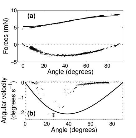
Fig. 4b shows that the torque is negative for all positive values. Thus the only stable orientation of the ellipse is the parallel one, . This contrasts with the Newtonian case, where long objects settle broadside-on Feng1994 . Note that in the case of a Stokes flow (without inertia nor elasticity), every orientation of the ellipse would be neutrally stable in an unbounded fluid Happel1983 , but that in the presence of boundaries, the parallel orientation is more stable Huang1998 . On the other hand, this is coherent with studies in other non-Newtonian fluids, where ellipses settle broadside-along under gravity in Oldroyd-B fluids Huang1998 or spherical particles aggregate vertically during sedimentation in shear-thinning fluids Daugan2002 . Actually, the stable orientation of long objects under flow is determined by a competition between inertia and viscoelasticity Liu1993 , which have opposite effects.
Fig. 4a shows that the lift is oriented downwards, as for a cambered airfoil, probably due to the positivity of the first normal stress difference Dollet : this should therefore be valid for every viscoelastic fluid Huang1998 .
It is worth noting that lift (Fig. 4a) and torque (Fig. 4b) are not maximal at the angle of 45∘. This contrasts with the existing prediction of the torque exerted on an ellipse by a second-order fluid in potential flow Wang2004 , which predicts an angular dependence of the form . We suggest two possible explanations for this discrepancy. First, the flow of foam is not potential, and even breaks the symmetry between upstream and downstream DolletThese . Second, second-order fluids might not be good models for foams, because they do not include yield stress.
In yield stress fluids, viscoplastic models predict that the drag on circular obstacles is proportional to the radius of the obstacle Mitsoulis2004 as long as the yield stress remains the preponderant contribution to the total stress. This agrees with experiments on circles Dollet2005 , and this is compatible with the proportionality of the drag with the leading length of the ellipse (Fig. 2). However, this scaling with the leading length does not hold for a square obstacle, which experiences a drag independent of its orientation Dollet2005 for reasons we do not understand yet. In addition, any orientation of a square obstacle is neutrally stable in a flowing foam Dollet2005 , whereas it would align its diagonals streamwise and spanwise in a viscoelastic liquid, as reported in Huang1998 .
To summarise, we are not aware of a single macroscopic, continuous (viscoelastic or viscoplastic) model which can explain the whole set of experimental data.
We now propose an elastic, microscopic model, to catch the main qualitative features of drag, lift and torque. We estimate the contribution of the soap film tension (which determines the normal tensile elastic stress Weaire1999 ; Janiaud2005 ) to the force on the ellipse. Since the foam is quasi-2D, each film separating two bubbles in contact with the obstacle exerts on it a force directed along the film; its magnitude is the line tension, , which is twice the air-water surface tension , multiplied by the foam height , and a prefactor accounting for 3D geometry Dollet . If the flow is quasistatic, the film is along the normal to the surface of the ellipse (see Fig. 1). The total force is thus a sum performed over the films in contact with the ellipse: . We do not model the contribution of the bubbles pressure, which is of the same order of magnitude, and is roughly proportional, to the contribution of the film tension Cox2006 ; DolletThese . We do not model either the velocity-dependent forces and torque, originating from the viscous friction within the lubrication films between the ellipse and the surrounding bubbles.
If the ellipse is much larger than the bubbles, we consider the distance between consecutive films along the ellipse as the continuous function , being the angle in the ellipse’s parametric equation: , , and write the force and torque as integrals:
| (2) | |||||
We then deduce the drag and lift as , and , respectively.
We must now model the function , or equivalently, the deformation of bubbles around the obstacle. As already mentioned in Dollet , this is strongly correlated to the local structure of the flow: if it converges towards the obstacle (leading side), it squashes the bubbles in contact, and is high. Conversely, if the flow diverges from the obstacle (trailing side), it stretches the bubbles in contact, and is low. Experimental images support this argument (Fig. 1), and, more precisely, lead us to set a phenomenological expression for . Fig. 1 shows that the bubbles remain squashed over the whole leading side ( with from elementary geometry); we thus assume that takes a maximum value, over this interval. At the trailing side, Fig. 1 shows that the bubbles are progressively stretched up to a maximum close to the point, which is close to the angle for simplicity. To reproduce this observation, we assume a piecewise affine variation of from to a minimal value in the ranges , and . The analysis of several images of the bubbles along the obstacle yields the following estimates: mm, and mm. Given the aspect ratio , we can calculate the drag, lift and torque from Eq. (2) (Fig. 4).
For the drag, it turns out that the result from Eq. (2) is indiscernible (with 1% precision, up to a free prefactor) with Eq. (1); the agreement with the experimental data is thus quite good (Fig. 4a). For the lift, we predict the sign, i.e. explains the downwards lift: the tensile stress is larger at the trailing edge where it contributes in average downwards (and downstream) for angles between 0∘ and 90∘, than at the leading edge, where it contributes upwards (and upstream). This confirms that the lift is dominated by the elasticity, as is the case for an airfoil Dollet . Moreover, we predict correctly the angular dependence of the lift, and a maximum at angle 40∘, which agrees quantitatively with the experiments. For the torque, the agreement is qualitative: we predict its sign, the existence of a maximum at an angle smaller than 45∘, and the stability (instability) of the parallel (perpendicular) orientations.
The present model relies mainly on the coupling between bubble deformation and flow. This argument has a very general validity: it explains the anti-inertial lift exerted by a flowing foam on an airfoil Dollet , and predicts quantitatively the drag on a circle on several decades of fluid fractions Raufaste . It also applies in 3D, as shown by the analogies between the 2D flow around a circle Dollet2005 and the 3D flow around a sphere deBruyn2004 ; Cantat2005b . It is qualitatively insensitive to the presence of channel walls, both because this does not influence the convergence or divergence of flow close to the obstacle, and because of the very limited lateral extent of the influence of an obstacle for foams Dollet2005 ; deBruyn2004 compared to Newtonian fluids.
Foams are often modelled as viscoplastic fluids, such as Bingham or Herschel-Bulkley models Lauridsen2002 . Such models describe yielding, which is occurring at the leading side, where the roughly constant amplitude of bubble deformation (Fig. 1) is a manifestation of yield strain. On the other hand, viscoelastic fluids such as the Oldroyd-B model often used for polymers Larson1999 describe the delayed, elastic response of the bubbles, apparent at the trailing side through the progressive stretching of the bubbles (Fig. 1).
Our phenomenological model captures both the coupling between strain and flow (with delayed response) and the saturation of deformation (yielding). It yields a good agreement with experimental data (Fig. 4). Still, we can suggest improvements in three directions. First, the law assumed for is a phenomenological description of observations. The next step would consist in predicting this function. This would require to quantify accurately the evolution of strain due to advection and plastic rearrangements of bubbles, which is predicted by recent models in the simple case of shear flow Weaire ; here, a generalization to more complex flows and geometries is required. Second, we could extend this model to describe the velocity-dependent contribution to drag, lift and torque. This requires to quantify precisely the influence of friction on the interaction between bubbles and obstacle boundaries Denkov2005 . Third, it would be useful to include the effect of sharp angles, in order to understand why the drag on a square does not depend on its orientation.
We have benefitted from stimulating discussions with J. Wang, S. Cox and C. Raufaste, as well as during the FRIT workshop.
References
- (1) D. Weaire, S. Hutzler, The Physics of Foams, Oxford University Press, Oxford (1999).
- (2) R. Höhler, S. Cohen-Addad, J. Phys. Condens. Matt. 17, R1041 (2005).
- (3) N. D. Denkov, V. Subramanian, D. Gurovich, A. Lips, Coll. Surf. A 263, 129 (2005).
- (4) I. Cantat, R. Delannay, Eur. Phys. J. E 18, 55 (2005).
- (5) D. Weaire, E. Janiaud, S. Hutzler, submitted, cond-mat/0602021.
- (6) B. Dollet, F. Elias, C. Quilliet, C. Raufaste, M. Aubouy, F. Graner, Phys. Rev. E 71, 031403 (2005).
- (7) S. Courty, B. Dollet, F. Elias, P. Heinig, F. Graner, Europhys. Lett. 64, 709 (2003).
- (8) J. R. de Bruyn, Rheol. Acta 44, 150 (2004).
- (9) M. D. Alonso, S. Hutzler, D. Weaire, S. J. Cox, in Proceedings of the 3rd Euroconference on Foams, Emulsions and their Applications, P. L. J. Zitha, J. Banhard, P. L. M. M. Verbist Eds., MIT Verlag, Bremen, 282 (2000).
- (10) I. Cantat, O. Pitois, J. Phys. Condens. Matt. 17, S3455 (2005).
- (11) S. J. Cox, M. F. Vaz, D. Weaire, Euro. Phys. J. E 11, 29 (2003).
- (12) C. Raufaste, B. Dollet, S. Cox, Y. Jiang, F. Graner, in preparation.
- (13) J. Feng, H. H. Hu, D. D. Joseph, J. Fluid Mech. 261, 95 (1994).
- (14) J. Happel, H. Brenner. Low Reynolds number hydrodynamics, Martinus Nijhoff Publishers, Den Haag (1983).
- (15) P. Y. Huang, H. H. Hu, D. D. Joseph, J. Fluid Mech. 362, 297 (1998).
- (16) S. Daugan, L. Talini, B. Herzhaft, C. Allain, Eur. Phys. J. E 7, 73 (2002).
- (17) Y. J. Liu, D. D. Joseph, J. Fluid Mech. 255, 565 (1993).
- (18) B. Dollet, M. Aubouy, F. Graner, Phys. Rev. Lett. 95, 168303 (2005).
- (19) E. Janiaud, F. Graner, J. Fluid Mech. 532, 243 (2005).
- (20) J. Wang, D. D. Joseph, J. Fluid Mech. 511, 201 (2004).
- (21) B. Dollet, Écoulements bidimensionnels de mousse autour d’obstacles, Ph.D thesis, Univ. Grenoble 1 (2005), unpublished, available at http://www-lsp.ujf-grenoble.fr/vie_scientifique/theses/datas/BenjaminDollet.pdf.
- (22) E. Mitsoulis, Chem. Eng. Sci. 59, 789 (2004).
- (23) S. Cox, B. Dollet, F. Graner, to appear in Rheol. Acta.
- (24) J. Lauridsen, M. Twardos, M. Dennin, Phys. Rev. Lett. 89, 098303 (2002).
- (25) R. G. Larson. The structure and rheology of complex fluids, Oxford University Press, New York (1999).