Micromagnetic simulations of the magnetization precession induced by a spin polarized current in a point contact geometry
Abstract
This paper is devoted to numerical simulations of the magnetization dynamics driven by a spin-polarized current in extended ferromagnetic multilayers when a point-contact setup is used. We present (i) detailed analysis of methodological problems arising by such simulations and (ii) physical results obtained on a system similar to that studied in Rippard et al., Phys. Rev. Lett., 92, 027201 (2004). We demonstrate that the usage of a standard Slonczewski formalism for the phenomenological treatment of a spin-induced torque leads to a qualitative disagreement between simulation results and experimental observations and discuss possible reasons for this discrepancy.
pacs:
85.75.-d, 75.75.+a, 75.40.Gb, 75.40.MgI Introduction
Nearly a decade after prediction SpInjPred and subsequent experimental discovery SpInjDiscov of magnetic excitation and magnetization switching induced by a spin-polarized current (SPC) in a thin magnetic film high-quality experiments providing quantitative information concerning the corresponding magnetization dynamics have been performed (see, e.g., Ref. Kiselev2003, ; Kiselev2004, ; Rippard2003, ; Rippard2004a, ; Rippard2004b, ). For this reason the important problem of the quantitative verification of existing theoretical models for the spin-transfer phenomena and SPC-induced magnetization dynamics SpInjTheory can be addressed. Corresponding research clearly requires full-scale micromagnetic simulations, because single-domain (macrospin) approximation Sun2000 by its definition can not incorporate important effects resulting from the inhomogeneity of the magnetization states. Such strongly non-uniform magnetization configurations during the SPC-induced precession are predicted already for thin film elements of very small sizes BerkovChaos2005 ( nm), which are less than typical dimensions of any actually used experimental samples.
Micromagnetic simulations performed up to now deal only with the experiments performed in the so called columnar geometry SimulColumnGeom , where an electric current flows through a multilayer magnetic element with very small lateral sizes nm. Such simulations were able to reproduce many important features of the experimental data obtained on columnar structures, in particular, the existence of regular and quasichaotic oscillation regimes, dependence of the oscillation frequency on the current strength etc. (however, we mention that even the most sophisticated model failed to reproduce experimental data quantitatively BerkovEllipse2005 ). In contrast to this situation, to the best of our knowledge, simulations of the point-contact experiments Rippard2004a ; Rippard2004b , which show some important magnetization dynamics features different from those observed on columnar structures, have not been carried out.
In this paper we present such full-scale micromagnetic simulations of the SPC-induced magnetization dynamics in the point-contact setup. The paper is organized as follows: in Sec. II we discuss methodological problems of such simulations which are specific for the geometry under study. Next (Sec. III) we present our results, starting from the analysis of the magnetization dynamics without the current-induced magnetic field (which enables a much more transparent presentation of several important effects). Brief comparison with the experimental data is performed in the last section.
II Methodological problems of numerical simulations in the point contact setup
Numerical simulations were carried out with our software package MicroMagus MicroMagus .This package uses the modified Bulirsch-Stoer algorithm with the adaptive step-size control for integrating the Landau-Lifshitz-Gilbert (LLG) equation to calculate the time evolution of the system magnetization configuration. For the additional torque created by the spin polarized current (SPC) we have assumed the symmetric Slonczewski form ( is the spin polarization direction) in order to study the SPC-induced dynamics in the simplest possible approximation. In the trilayer system under study (see below) the spin torque was assumed to act on the on the magnetization of the ’free’ layer only. The site dependence of the spin torque magnitude (in the first approximation confined within the point contact area) is discussed below.
To enable a comparison with the experimental results reported in the most advanced quantitative studies of magnetization oscillations in the point contact geometry Rippard2004a ; Rippard2004b , we have chosen the system parameters as close as possible to those reported in Ref. Rippard2004a, . We have simulated a trilayer system consisting of two magnetic layers and an interlayer non-magnetic spacer: the lower ’fixed’ layer (underlayer) with the thickness nm and magnetic parameters typical for Co90Fe10 (saturation magnetization G, exchange constant erg/cm); the upper (thin) Permalloy-like magnetic layer with the thickness nm and G (as measured in Ref. Rippard2004a, ) and erg/cm (standard value for Py Doering1966 ); the spacer thickness was set to nm as for the Cu spacer used in Ref. Rippard2004a, . All results presented below were obtained for an external field Oe. Coordinate axes and lie in the film plane, with the -axis directed along the external field.
The ’fixed’ layer thickness nm was taken less than the experimental value Rippard2004a nm, because proper simulations of such relatively thick layers require not only their in-plane discretization, but also the subdivision into sublayers, which would lead in this case to prohibitively large computational times; the influence of underlayer thickness on the magnetization dynamics will be discussed elsewhere.
We also did not study the effect of the polycrystalline structure of Co90Fe10 underlayer, although the magnetocrystalline anisotropy of this material is not negligible (cubic anisotropy with erg/cm3 was reported in Ref. CoFeAnis, ). The magnetization dynamics of the system under study turned out to be very complicated already for ideal layers (without taking into account their polycrystalline structure and corresponding random anisotropy), so we have postponed the study of the random magnetocrystalline anisotropy effects.
In contrast to micromagnetic study of spin injection effects observed in the columnar structures Kiselev2003 ; Kiselev2004 , where standard micromagnetic methods can be applied SimulColumnGeom , simulations of the point-contact experiments encounter serious methodological problems. Here we discuss two of them: (i) artificial interference effects occurring both for open and periodic boundary conditions and (ii) artificial short-wave magnetization oscillations arising by the usage of a sharp cut-off of charge and spin currents.
Artificial interference effects. This problem occurs due to the combination of two circumstances: first, for practical purposes magnetic materials with low dissipation rate are used (to ensure a small linewidth of the oscillation spectrum and a reasonably low excitation threshold), and second, a lateral size of a system available for simulations is much smaller than that used experimentally. In real experiments the lateral size of a multilayer is about 10 mkm Rippard2004a , which is definitely far above the value accessible for numerical simulations, especially taking into account that dynamic simulations require a much finer mesh than quasistatic ones. In particular, we have found out that to obtain a mesh-independent results for a system with geometric and magnetic parameters given above, a lateral discretization as fine as nm2 is necessary, which limits the simulated lateral system size to mkm2 (which means more cells per layer). In a layer made of a material with low dissipation (see above) the decay length of the spin wave with the wavevector corresponding to the inverse size of the point contact has the same order of magnitude as the simulated area size.
When open boundary conditions (OBC) are used (i.e., a finite size element is simulated), this means that the wave emitted by the point contact propagates across the whole element, is reflected at its free borders and returns to the contact location. The strong interference of this reflected wave with primary (SPC-induced) magnetization oscillations leads to unphysical artifacts, especially taking into account that both waves have the same frequency. Another problem arising by using OBC is a complicate pattern of the wave reflection due to the inhomogeneous magnetization configuration on the element edges.
For periodic boundary condition (PBC) the magnetization configuration at the simulated area borders is homogeneous (which is the main reason to use PBC), but the primary wave also propagates across the whole simulated area and due to PBC enters this area from the opposite side, causing the same undesirable interference effects. To eliminate this effects, a method to absorb the wave near the simulation area borders, not affecting the low dissipation at and near the point contact, is required.
To ensure such an absorption, we have embedded in our code an artificial site dependence of the dissipation coefficient . The function describing this dependence should fulfil several conditions: (i) the dissipation within and nearby the point contact area should remain equal to its physical value to preserve the dynamic properties of the system under study, (ii) the dissipation coefficient far from the point contact (near the simulation area borders) should be large enough to ensure the wave energy absorption, (iii) spatial variation should be smooth enough to prevent the wave reflection from the border between the areas of small and relatively large (due to the abrupt changes of the media properties). Following these requirements, we have adopted a site-dependent dissipation in the form
| (1) |
Here it is assumed that the point contact is located at the coordinate origin. The function (1) provides a gradual increase of the dissipation parameter above the (small) basic value which starts at the distance from the point contact and occurs smoothly within a ring of the width . The maximal dissipation value reached outside of this ring is . We have found out that for the system size mkm2 and basis dissipation values in the range the introduction of the additional dissipation (1) with nm, and ensured the wave absorption at the simulation area borders, not changing the magnetization dynamics within and around the point contact area. For simulations considered here we have used the basis dissipation value .
Spurious magnetization oscillations caused by a sharp spatial cut-off of a point-contact current. By simulations of the columnar geometry the current is usually assumed to be distributed homogeneously within the layer plane of a nanoelement, which does not lead to any methodical problems because the magnetization is also present only inside the area where the current flows. In contrast to this simple situation, by simulations of a point-contact setup the naive usage of the step-like current density in the form and ( being the distance from the contact center, - the contact diameter) lead to the development of artificial magnetization oscillations with the smallest wavelength supported by the given lattice. The reason for these oscillations is the non-physical abrupt change of the current density at , so that its spatial Fourier image and the Fourier image of the current-induced magnetic field (the Oersted field) exhibits large tails up to the highest values of the wavevectors available for the simulated discrete system. This leads to artificial instabilities for these wavevectors, resulting in the appearance of corresponding magnetization oscillations.
In order to avoid this problem, we have smoothed the spatial distribution of obtained in the approximation of a sharp electric current cut-off convolving it with the Gaussian kernel . A physically meaningful choice of the smoothing parameter would require a reliable information about the lateral diffusion of the electric current carriers to calculate the actual spatial distribution of the current density. Lacking such knowledge, we have simply adopted the minimal value (two times larger than the mesh size) which was sufficient to eliminate the artificial oscillations mentioned above. Further increment of this parameter within a reasonable range (up to ) had only a minor influence on physical results.
A similar problem is caused by the sharp spatial cut-off of the spin current density represented by the amplitude of the SPC-induced torque , although spatial oscillations caused by this cut-off are weaker than discussed in the previous paragraph. Nevertheless, the same kind of smoothing is also required to solve this problem. The smoothing parameter of the corresponding kernel is directly related to the spin diffusion length and could in principle be computed from the corresponding theory. In this study, however, we have also simply used the value for the same reasons as explained above for . At this point we would like to emphasize, that - in contrast to the Oersted field smoothing parameter - the -value significantly influences the system behaviour; in particular, the threshold value of for the onset of steady-state microwave oscillations substantially depends on . For this reason the problem of calculating the actual distribution of a spin current in the point contact geometry deserves spatial attention.
All results presented below were obtained employing the site-dependent damping (1) and smoothing of the Oersted field and spin current distribution with parameters given above. The in-plane discretization of both magnetic layers with the mesh size nm2 and the full size of the simulation area mkm2 (with PBC) were used. The point contact diameter was set to nm.
III Numerical simulations: Results and discussion
In this paper we discuss only simulation results obtained without taking into account the effect of thermal fluctuations (). Even without these effects the system demonstrates very complicated dynamics, which should be understood before thermal fluctuations are included into consideration.
Dynamics without taking into account the Oersted field. We start with the analysis of the magnetization dynamics when the influence of the Oersted field is neglected. We point out already here that in the experimental situation Rippard2004a the current-induced magnetic field is comparable with the externally applied field: For the total current mA flowing through the point contact with the diameter nm the maximal value of the Oersted field is Oe, whereas the external field used in Ref. Rippard2004a, to present most detailed results is Oe. For this reason we do not expect the approximation when is neglected to be quantitatively correct, but neglecting the Oersted field simplifies the magnetization dynamics of the system under study, preserving most of its qualitative features, which can be thus demonstrated more clearly.
The major feature of the simulated magnetization dynamics in the point contact geometry is the existence of two current regions where the steady-state precession of the magnetization within and nearby the point-contact area exists (Fig. 1).
In the first current region - before the magnetization in the point contact area is switched under the SPC influence, i.e., when the magnetization is (on average) still directed along the external field, the magnetization dynamics is relatively simple. Magnetization configuration of the thin (upper) layer within the point-contact area remains roughly collinear. Spin waves emitted from the area under the contact are smooth and have a simple elliptical wavefront (Fig. 1). The limit oscillation cycle of the magnetization averaged over this area represents a slightly bended ellipse (Fig. 2), time dependencies of the magnetization components are nearly ideal harmonic functions, so that oscillation power spectra consist of a single and very narrow peak. As usual for such in-plane oscillations, the frequency of -oscillations (the component along the external field ) is twice the -frequency (the in-plane component perpendicular to ), because goes back and force twice during a single oscillation cycle. The oscillation frequency decreases monotonically with increasing current ( in our formalism), which is mainly due to the increase of the oscillation amplitude (longer limit cycle) with the current strength. The oscillation power sharply increases when the current exceeds the threshold for the oscillation onset and then growth smoothly until the magnetization under the point contact area is switched by the SPC.
It turns out, however, that in the model simulated here a steady-state precession exists also after the point contact area switching caused by spin injection. By the transition to this second regime we observe a large frequency jump - for the system parameters used in this study the frequency drops down from GHz to GHz and then remains almost current-independent. Although the limit cycles have in this regime a more complicated form and the time dependencies of the magnetization components considerably differ from ideal sinusoids, spectral lines are still so narrow, that within the physical time corresponding to the longest simulation run performed ( ns) their width could not be resolved ( MHz). Oscillation amplitude slowly decreases with current leading to the corresponding decrease of the oscillation power.
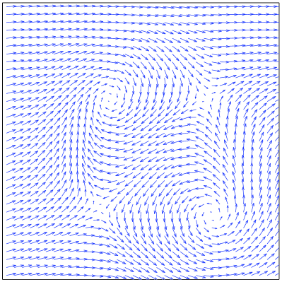
Although spectral lines in this second precession mode remain quite narrow, the magnetization configurations appearing during the precession are extremely complicated even when the Oersted field is neglected. First of all we note that the precession frequency is below the frequency of the homogeneous FMR mode for the layer under consideration ( GHz. For this reason the ’normal’ circular (elliptical) wave can not exist in this regime, so that the energy is emitted in form of the soliton-like wave packages, as shown in Fig. 3. The magnetization within and nearby the contact area itself forms vortex/antivortex pairs (the latter state is also sometimes called a cross-like configuration), which creation and annihilation is the basic feature of the magnetization dynamics in this regime; a typical example of such a structure is shown in Fig. 4. Detailed analysis of these challenging structures will be performed elsewhere.
Dynamics with the Oersted field included. Inclusion of the Oersted field requires the establishing of the relation between the current strength used in the actual experiment and the parameter used in simulations to set the amplitude of the SPC-induced torque. Lacking the exact microscopic theory which could provide such a relation, we have used the same procedure as in Ref. BerkovEllipse2005, , i.e., we assumed that the oscillation onset threshold corresponds to the minimal current mA where the magnetization precession is observed experimentally.
The current-induced magnetic field , being strongly inhomogeneous, results in a much more complicated magnetization dynamics than in the absence of . The most obvious change is the appearance of the wave asymmetry in the steady-state precession regime before switching: in that half of the layer where the Oersted field is directed opposite to the external field (thus partly compensating it), the wave amplitude is significantly larger than in the other half of the film (where the external field is enhanced by ). The inhomogeneity of leads also to further complication of the magnetization states in the ’after-switching’ regime: the number of vortex-antivortex pairs which might exist simultaneously increases and the precession trajectory (limit cycle) of the average magnetization of the point-contact area becomes quasiperiodic. The complete analysis of the corresponding dynamics will be also presented elsewhere.
The major effect of the current-induced field is, however, not the quantitative changes in the ’before-’ and ’after-switching’ precession modes discussed above, but the appearance of a new intermediate regime in-between these two current regions. Corresponding interval is marked in Fig. 5 by the legend ’Complicated magnetization dynamics’. For currents within this interval ( for parameters used in our simulations) the projection of the magnetization under the contact area exhibits relatively rare transitions between the values close to the maximal possible value and values close to (Fig. 6a). Correspondingly, its power spectrum (Fig. 6b) has a large component at (relatively) low frequencies. The projection of the magnetization (in-plane projection perpendicular to the external field) oscillates with very different frequencies depending on the -value, i.e., on the magnetization configuration in the point contact region: for nearly homogeneous magnetization state ( close to 1) the oscillation frequency of is much higher than for a strongly inhomogeneous configuration (small values of ). Oscillation power spectrum of consists of several relatively broad lines, which quantitative analysis requires better simulation statistics (longer runs) than those which could be carried out up to now.
IV Comparison with experimental data
In this last section we briefly compare our simulation data with experimental results from Ref. Rippard2004a, . First, we note that several important features of experimentally observed magnetization precession in the point contact setup could be reproduced by our simulations. In particular, in the oscillation regime before switching we have obtained, in accordance with Ref. Rippard2004a, , very narrow spectral lines (in our simulations the linewidth was MHz) and nearly linear decay of the oscillation frequency with increasing current (see Fig. 1a and 5a). Such extremely small linewidths can be naturally explained by a smooth variation (in space) of the magnetization configuration, which is due to the absence of strong demagnetizing field effects characteristic for nanoelements in the columnar geometry (see, e.g., Ref. Kiselev2003, ; Kiselev2004, ; SimulColumnGeom, ). The decrease of the oscillation frequency with increasing current is a consequence of the growing precession amplitude when the current (and hence - the spin torque magnitude) is increased, which for non-linear oscillations results in the larger precession period.
More important, however, are the disagreements between simulated and measured data, among which the qualitative one - the existence of at least two oscillation regimes for the simulated precession (whereby only one precession regime was observed experimentally) - is the major problem. There are several possible reasons for this discrepancy, among them (i) the simplicity of the torque term used in simulations (for more complicated forms which should be tested next, see Ref. Slonczewski2002, ; Xiao2004, ), (ii) influence of the SPC-induced effective field recently measured in Ref. Zimmler2004, , (iii) exchange weakening within magnetic layers resulting from the local Joule heating (in the point contact geometry this effect may be especially pronounced due to high current densities required to induce magnetization oscillations) and (iv) substantial contribution of the layer regions outside the point contact area to the measured microwave oscillation spectra. In particular, for the last mentioned reason, the signal from these regions would be present in the regime before switching, but nearly absent for the ’after-switching’ mode (as it can be seen from the comparison of right panels of Fig. 2 and 3), thus strongly enhancing the oscillation power in the regime before switching compared to the second regime. However, to clarify whether it is really the case, calculations of the current distribution for the concrete experimental setup are required.
Another interesting problem is the existence of a strong second harmonic in the experimentally measured spectrum. Its presence could be caused by the local (under the point contact) deviation of the underlayer magnetization from the external field direction. This would lead to the contributions from the oscillations of both longitudinal () and transverse () in-plane magnetization components, thus providing the required second harmonic () and basic () oscillation frequency BerkovEllipse2005 . Such a magnetization deviation from the direction could exist due, e.g., to the random magnetic anisotropy of crystallites. Another explanation of the second harmonic presence could be the above mentioned contribution of the area around the point contact, because due to the local conservation of the magnetic moment magnitude the waves of both - and -components contain both frequencies (see Fig. 2, right panels).
V Conclusion
In conclusion we point out that full-scale micromagnetic simulations (performed in frames of the Slonczewski formalism) of the magnetization dynamics induced by a spin-polarized current in the point contact geometry recover several important features of experimental observations, like very narrow spectral lines and current dependence of the oscillation frequency. However, if we assume that the measured signal comes solely from the magnetization oscillation under the point contact area, simulations results exhibit serious qualitative disagreements with experimental data, the main of which is the existence of at least two precession modes in the two current intervals corresponding to (i) the precession around the external field direction (’before-switching’ mode) and (ii) around the direction opposite to (’after-switching’ mode). This disagreement clearly shows that further refinement of theoretical models is required for understanding of the spin torque induced magnetization excitations in point-contact experiments.
References
- (1) J.C. Slonczewski, J. Magn. Magn. Mat., 159, L1, (1996); L. Berger, Phys. Rev. B, 54, 9353 (1996)
- (2) J.Z. Sun, J. Magn. Magn. Mat., 202, 157 (1999); M. Tsoi, A.G.M. Jansen, J. Bass, W.-C. Chiang, M. Seck, V. Tsoi, P. Wyder, Phys. Rev. Lett., 80, 4281 (1998)
- (3) S.I. Kiselev, J.C. Sankey, I.N. Krivorotov, N.C. Emley, R.J. Schoelkopf, R.A. Buhrman, D.C. Ralph, Nature, 425, 380 (2003);
- (4) S.I. Kiselev, J.C. Sankey, I.N. Krivorotov, N.C. Emley, M. Rinkoski, C. Perez, R.A. Buhrman, D.C. Ralph, Phys. Rev. Lett., 93, 036601 (2004).
- (5) W.H. Rippard, M.R. Pufall, T.J. Silva, Applied Physics Letters 82, 1260 (2003).
- (6) W.H. Rippard, M.R. Pufall, S. Kaka, S.E. Russek, T.J. Silva, Phys. Rev. Lett., 92, 027201 (2004)
- (7) W.H. Rippard, M.R. Pufall, S. Kaka, T.J. Silva, S.E. Russek, Phys. Rev. B, 70, 100406(R) (2004)
- (8) X. Waintal, E.B. Myers, P.W. Brouwer, D.C. Ralph, Phys. Rev. B, 62 12317 (2000), M.D.Stiles, A.Zangwill, Phys. Rev. B, 66 014407 (2002) M.D.Stiles and A.Zangwill, J. Appl. Phys. 91 6812 (2002)
- (9) J.Z. Sun, Phys. Rev. B, 62 570 (2000)
- (10) D.V. Berkov, N.L. Gorn, Phys. Rev. B, 71 052403 (2005)
- (11) J. Miltat, G. Albuquerque, A. Thiaville, C. Vouille, J. Appl. Phys., 89, 6982 (2001), Z. Li, S. Zhang, Phys. Rev. B, 68 024404-1 (2003), J.-G. Zhu, X. Zhu, IEEE Tarns. Magn., 40, 182 (2004), X. Zhu, J.-G. Zhu, R.M. White, J. Appl. Phys., 95, 6630 (2004), K.J. Lee, A. Deac, O. Redon, J.P. Nozieres, B. Dieny, Nature Materials, 3 (2004) 877
- (12) D.V. Berkov, N.L. Gorn, to appear in: Phys. Rev. B, Sept. 2005; see also: cond-mat/0503754
- (13) D.V. Berkov, N.L. Gorn, MicroMagus - package for micromagnetic simulations, http:www.micromagus.de
- (14) M.D. Stiles, J. Xiao, A. Zangwill, Phys. Rev., B69 (2004) 054408; M.L. Polianski, P.W. Brouwer, Phys. Rev. Lett., 92 (2004) 026602
- (15) W. Doering, Micromagnetismus, in: Handbook of Physics, ed. by S. Fl gge, Springer-Verlag Berlin, 1966
- (16) J. Pelzl, R. Meckenstock, D. Spoddig, F. Schreiber, J. Pflaum, Z. Frait, J. of Phys.: Cond. Matt. 15 (2002) S451
- (17) J.C. Slonczewski, J. Magn. Magn. Mat., 247 324 (2002)
- (18) J. Xiao, A. Zangwill, M.D. Stiles, Phys. Rev. B, 70, 172405 (2004)
- (19) M.A. Zimmler, B. Özyilmaz, W. Chen, A.D. Kent, J.Z. Sun, M.J. Rooks, R.H. Koch, Phys. Rev. B 70 (2004) 184438