Co-rich decagonal Al-Co-Ni: predicting structure, orientational order, and puckering
Abstract
We apply systematic methods previously used by Mihalkovič et al. to predict the structure of the ‘basic’ Co-rich modification of the decagonal Al70Co20Ni10 layered quasicrystal, based on known lattice constants and previously calculated pair potentials. The modelling is based on Penrose tile decoration and uses Monte Carlo annealing to discover the dominant motifs, which are converted into rules for another level of description. The result is a network of edge-sharing large decagons on a binary tiling of edge 10.5 Å. A detailed analysis is given of the instability of a four-layer structure towards -doubling and puckering of the atoms out of the layers, which is applied to explain the (pentagonal) orientational order.
1 Introduction
A fundamental problem of theoretical solid-state chemistry is, assuming the ability to compute perfectly the total energy of a complex compound, to discover which arrangement of the atoms minimizes that energy. Quasicrystals offer a wonderful opportunity to face this problem, as many different arrangements are low in energy, but this approximate degeneracy is resolved by more subtle interactions, often in several steps of a hierarchy of length scales.
Consider decagonal Al-Co-Ni, the pre-eminent decagonal Al-TM quasicrystal (TM= transition metal), a phase which is divided into many modifications [1], of which the simplest are ‘basic’ Ni-rich (around Al70Co10Ni20) and ‘basic’ Co-rich (around Al70Co20Ni10). Mihalkovič et al [2] proposed a general method to discover the ground-state structure, taking as inputs the interatomic pair potentials, derived by Moriarty and Widom [3] using ‘generalized pseudopotential theory’, and the experimentally determined lattice constants. One initially describes the quasicrystal by a Penrose tiling of edge Å with properly placed candidate sites on the tiles. Monte Carlo annealing, in which atoms hop on these sites, is used to find low-energy configurations. (This approach was used earlier by Cockayne and Widom [4]
for decagonal Al-Co; Mihalkovič et al [2] added tile rearrangements as a helpful Monte Carlo move.). In the next stage, motifs abstracted from these results are converted into rules to decorate larger tiles, thereby reducing the degrees of freedom and permitting larger simulation cells in which further orderings can be seen.
2 Structure motifs and idealized decoration
We have applied this method to the ‘basic’ Co-rich composition (more complete accounts may be found in Refs. [5, 6].) From the initial stage simulation it became clear that the dominant motif is a decagon with edge Å and hence diameter Å; in this rest of this paper, the term ‘13 Å Decagon’ refers exclusively to this object. The exact occupancies (fig. 1a) were clarified in the second stage of simulations. These were based on -edge rhombi in arrangments favoured the densest possible packing of non-overlapping 13Å decagons made from the rhombi. (Overlaps were verified to be unfavourable energetically.) The atoms in a cluster are grouped into concentric rings (see figure 1a). Just inside the perimeter, a few Al sites form a partial ‘ring 2.5’ with elusively context-dependent occupancies. (The Al positions on each 13Å Decagon edge (ring 3) also may depend on the 13Å Decagon’s environment.) Almost all the TM atoms in the 13Å Decagon are Co, which is presumably why it emerges at higher Co content. (This was also discovered by Hiramatsu and Ishii [7], who did an exploratory study using the same code of a wider range of AlCoNi compositions.)
The best arrangements for edge sharing of the 13Å Decagons amounts to a 10.5 Å edge ‘binary tiling’ [8, 9], with the 13Å Decagons sitting on the Large-atom sites of the binary tiling. Filling the space between is a secondary motif, which is centred on the Small-atom sites, which we call the ‘Star cluster’ and show in figure 1(b). The centre of this cluster has a pentagon of five candidate TM sites, which are variably occupied by TM (almost always Ni) or Al.
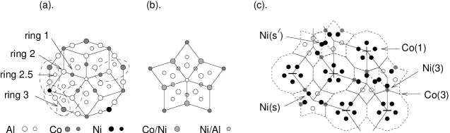
The TM occupancies show context dependence, which we will approximate with a very simple rule (figure 1c). We have four classes of TM atom. On each of the binary tiling’s Large vertices we have a 13Å Decagon with five Co(1) in its centre and ten TM(3) on its perimeter (ring 3). (For visual clarity, the TM(3) are not shown in figure 1c.) Now, on each (binary-tiling) edge connecting a 13Å Decagon to a Star cluster centre, a Star cluster TM is strongly favoured or disfavoured according to whether the 13Å Decagon’s first ring has Al or TM on the same edge. (The distance between these sites is Å, which is a maximum of [3].] So, on every binary-tiling rhombus exactly half the edges do not pass over a Co(1): let us place on each such edge a Ni within the Star cluster, and make the TM(3) site a Ni(3); all other TM(3) become Co(3). (As in the ‘basic’ Ni-rich composition, the difference between Ni and Co potentials favours Ni occupancy in TM-TM pairs and Co in lone TM sites.)
Finally, as this too is energetically favoured, we place 2 Ni wherever two Star clusters overlap, that is once on each Thin rhombus of the binary tiling. In a decagonal tiling, there is an average of Ni on each Star cluster and the composition is Co21.2Ni8.8 (assuming the TM fraction is 30%). (One other version of the idealization, including the placement of Al atoms, is described by Gu et al [6], and gave a composition Al70.1Co22.4Ni7.5, and it is even easier to devise variants with higher Ni content.)
3 Orientational order and puckering
A full structure description must specify, in each 13Å Decagon’s first ring, the orientation of the pentagon formed by its ring 1 TM atoms (this is prominent in electron microscope images). Each orientation is parametrized by a spin-like variable , with when the Co5 pentagon (projected on the plane) points up, that iswhen the five Co lie in the even-numbered atom layers. We seek an effective interaction of neighboring 13Å Decagon’s, like the spin interaction in an Ising model. A cluster arrangement with all clusters oriented the same will be called ‘ferromagnetic’; that quasicrystal has global pentagonal (not decagonal) symmetry, as is observed in fact for one of the Co-rich modifications [12, 13].
3.1 Fixed site list: interaction via Star clusters
When we simulate with a fixed site list, there are small energy differences that favour either the ‘ferromagnetic’ or ‘antiferromagnetic’ order of 13Å Decagon orientations, depending on the atom density assumed and which approximant is studied, showing there are competing contributions to the cluster-cluster effective interaction. (The ‘ferromagnetic’ effect wins for 0.068 0.074 Å-3, which includes the physically more reasonable densities.)
Where does the interaction come from? The only atoms that change with a cluster’s orientation are the central Al and the ring 1 Al5Co5, but those are too distant to interact directly. (Our potentials were cut off around 7Å.) An indirect interaction may be mediated by other atoms in two ways. Firstly, the variable Al atoms in rings 2.5 and 3 are within range of ring 1 of both clusters; this guides whether the ring 3 Al (in projection) divide the 13Å Decagon edge in the ratio or (See figure 1a.) This contribution favours ‘ferromagnetic’ order, so the shared 13Å Decagon edges will match. (Expressed in energy terms, the argument is related to the one for the ‘puckering’ case in Sec. 4, below.)
Alternatively, neighboring TM atoms in the Star clusters interact with each other and also respond to the first-ring orientations of adjoining 13Å Decagons: we suggest this is the origin of the ‘antiferromagnetic’ coupling, based on the TM rules of Sec. 2. Let us assume a repulsive energy for Ni-Ni pairs on edges differing by as found by Mihalkovič et al [2] in ‘basic’ Ni modification. One such pair appears on each Fat rhombus having 13Å Decagons with the same orientation. The effective orientation interaction is then favouring the ‘antiferromagnetic’ arrangement. Thus, the two indirect effects are indeed competing.
4 Relaxation and puckering
Relaxation and molecular dynamics of the structures found in the fixed-site simulation were used to explore subtler aspects corresponding to small energy differences – including the relative orientation of neighboring clusters, which is a major focus of this paper. The most striking effect of letting atoms off of the fixed sites was that Al atoms in ring 2.5/ring 3 tended to run to new locations, in which they displaced from the layers in the direction (puckering of atom layer). When we used a simulation cell with four layers, pattern of puckering is such that lattice constant doubled to Å. (That is the observed period of most Co-rich decagonal Al-Co-Ni modifications and approximants, and it was long known crystallographically that puckerings are the major way in which the real cells are doubled.)
4.1 Channels
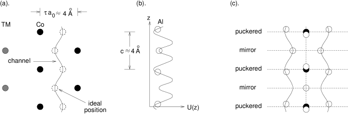
How shall we best understand the positions taken by Al after they are freed from the fixed site list? Let us consider the net potential felt by an Al given the TM atoms, which we fix on ideal sites (they hardly displace under relaxation in any case). Winding one-dimensional ‘channels’ are found along which the potential is low and comparatively flat, typically between two columns of Co atoms (a ubiquitous pattern in the structure) forming a zigzag ladder, as shown in figure 2a. (Henley et al [14] discovered similar channels in ‘basic’ Ni-rich modifications from the time-averaged Al density in a molecular dynamics simulation.)
The single-Al potential in a channel may be approximated as
| (1) |
Using our potentials, eV is found. Let us explain the origin of these coefficients. The Co atoms adjacent to the channel have symmetry under one-layer shifts, which explains the period- term of (1). Its minimum occurs in each atom layer, where the Al atom would be equidistant from three Co atoms at Å, the minimum of the pair potential.
Figure 2 shows another column of TM farther away which breaks the degeneracy between even and odd layers. This explains the period- term in equation (1), in which is the ‘spin’ variable defined above, and (resp. ) when the distant Co atoms are in even (or odd respectively) layers. (The deeper minima occur in the TM-poor layer.) Note that is proportional to , which happens to have a maximum at Å, the distance to the distant column.
4.2 Puckering
Now, three Al atoms can and do fit into every four layers: their mean separation Å is right at the Al-Al hardcore radius. Just where do they prefer to lie in each channel? The optimum configuration has a symmetry such that , , [so the puckering displacement from a layer is ; here is any integer.] The total energy (per Al) is
| (2) |
where is the Al interaction along the channel. [Note a small abuse in this approximation: since the channels are not straight, the actual Al-Al distance is not just a function of [6]. Inserting into equation (2) and Taylor expanding in , we obtain
| (3) |
Here . Also, , etc; inserting their values from equation (1), minimizing with respect to , and using , we find the energy minimumn
| (4) |
It can be seen this solution is favourable when ; that is, the local mirror layer of the Al’s in each channel lies in the TM-rich layer [as observed in real Al-TM structures.] Then, when two (equi)distant TM columns affect the channel, in equation (4) and the lowest is obtained when . Thus the relaxed total energy of channel Al favours a ‘ferromagnetic’ alignment of orientations, as was claimed.
Each channel breaks -translation symmetry in that the mirror-layer Al sits at either or , but not both. These channels interact, in a pattern [6] whereby four channels get occupied around a single TM column, as shown schematically in figure 2c; viewed in projection, the mirror-layer Al atoms involved in the channels form a sort of bent cross.
5 Conclusion
To summarize, the methods developed by Mihalkovič et al [2] in a study of the ‘basic’ Ni-rich decagonal Al70Co10Ni20 quasicrystal has successfully led to a structural understanding (at ) of ‘basic’ Co-rich decagonal Al70Co20Ni10, which is described by a completely different tiling, despite a very similar nearest-neighbor order. In this case, the key motif is a Å diameter decagon having a pentagonal core.
We applied our approach to a unit cell the same size as W(Al-Co-Ni), a crystalline approximant of ‘basic Co’. Many details of our prediction (most importantly the 13Å Decagons, and the locations of their centres) are in agreement with the experimentally solved structure [17]. However, W(Al-Co-Ni) has a few highly puckered sites which can not be captured in our approach which begins using a fixed-site list and relaxes afterwards. [Mihalkovič and Widom [10] have given a more thorough ab-initio investigation of W(Al-Co-Ni).]
In general, the simulations with a fixed-site list – followed blindly – would lead to an imperfect description of Al atoms in ring 2.5 and ring 3 of the 13Å Decagon. In simulations with relaxations (and in reality), many of these atoms displace from the layers, in a fashion which we have explained on the basis of the pair potentials.
References
References
- [1] S. Ritsch, C. Beeli, H. U. Nissen, T. Gödecke, M. Scheffer, and R. Lück 1998, Phil. Mag. Lett. 78: 67.
- [2] M. Mihalkovič, I. Al-Lehyani, E. Cockayne, C. L. Henley, N. Moghadam, J. A. Moriarty, Y. Wang, and M. Widom, 2002, Phys. Rev. B 65: 104205.
- [3] J. A. Moriarty and M. Widom 1997, Phys. Rev. B 56: 7905.
- [4] E. Cockayne and M. Widom 1998, Phil. Mag. A 77, 593.
- [5] N. Gu, M. Mihalkovič, and C. L. Henley 2005a, submitted to Phil. Mag. Lett.
- [6] N. Gu, M. Mihalkovič, and C. L. Henley 2005b, unpublished (in preparation).
- [7] S. Hiramatsu and Y. Ishii, unpublished (reported in Third Asian Intl. Workshop on Quasicrystals. Taipei, Taiwan, 2004).
- [8] F. Lançon, L. Billard, and P. Chaudhari 1986, Europhys. Lett. 2: 625.
- [9] M. Widom, K. J. Strandburg, and R. H. Swendsen 1987, Phys. Rev. Lett. 58: 706.
- [10] M. Mihalkovič and M. Widom 2006 Phil. Mag. A, to appear (these proceedings).
- [11] S. Deloudi and W. Steurer, Phil. Mag. A, to appear (these proceedings). ‘5-D Modelling of Decagonal Al-Co-Ni Quasicrystals, Starting from the W-Approximant’
- [12] S. Ritsch, C. Beeli, and H.-U. Nissen 1996 Phil. Mag. Lett. 74: 203.
- [13] X. Z. Li, R. C. Yu, K. H. Kuo, and K. Hiraga 1996, Phil. Mag. Lett. 73: 255.
- [14] C. L. Henley, M. Mihalkovič, and M. Widom 2002, J. All. Compd. 342: 221.
- [15] S. Hiramatsu 2006, Phil. Mag. A, to appear (these proceedings). ‘Phonon Spectra of Al-Ni-Co Decagonal Quasicrystals Modeled by Ab-Initio Interatomic Pair Potentials’
- [16] S. Hocker, F. Gähler, and P. Brommer 2006, Phil. Mag. A, to appear (these proceedings). ‘Molecular Dynamics Simulation of Aluminium Diffusion in Decagonal Quasicrystals’
- [17] K. Sugiyama, S. Nishimura, and K. Hiraga 2002, J. Alloy Comp. 342: 65